EP4268968B1 - Séparateur à cyclone permettant de séparer des solides et/ou des liquides d'un flux de processus - Google Patents
Séparateur à cyclone permettant de séparer des solides et/ou des liquides d'un flux de processus Download PDFInfo
- Publication number
- EP4268968B1 EP4268968B1 EP22170817.5A EP22170817A EP4268968B1 EP 4268968 B1 EP4268968 B1 EP 4268968B1 EP 22170817 A EP22170817 A EP 22170817A EP 4268968 B1 EP4268968 B1 EP 4268968B1
- Authority
- EP
- European Patent Office
- Prior art keywords
- cyclone separator
- guide means
- section
- cross
- process chamber
- Prior art date
- Legal status (The legal status is an assumption and is not a legal conclusion. Google has not performed a legal analysis and makes no representation as to the accuracy of the status listed.)
- Active
Links
Images


Classifications
-
- B—PERFORMING OPERATIONS; TRANSPORTING
- B04—CENTRIFUGAL APPARATUS OR MACHINES FOR CARRYING-OUT PHYSICAL OR CHEMICAL PROCESSES
- B04C—APPARATUS USING FREE VORTEX FLOW, e.g. CYCLONES
- B04C5/00—Apparatus in which the axial direction of the vortex is reversed
- B04C5/08—Vortex chamber constructions
- B04C5/103—Bodies or members, e.g. bulkheads, guides, in the vortex chamber
-
- B—PERFORMING OPERATIONS; TRANSPORTING
- B04—CENTRIFUGAL APPARATUS OR MACHINES FOR CARRYING-OUT PHYSICAL OR CHEMICAL PROCESSES
- B04C—APPARATUS USING FREE VORTEX FLOW, e.g. CYCLONES
- B04C5/00—Apparatus in which the axial direction of the vortex is reversed
- B04C5/12—Construction of the overflow ducting, e.g. diffusing or spiral exits
- B04C5/13—Construction of the overflow ducting, e.g. diffusing or spiral exits formed as a vortex finder and extending into the vortex chamber; Discharge from vortex finder otherwise than at the top of the cyclone; Devices for controlling the overflow
Definitions
- the present invention relates to a cyclone separator for separating solids and/or liquids from a process stream.
- the present invention further relates to a method for operating such a cyclone separator and a cyclone separator system with such a cyclone separator.
- Such cyclone separators are known from the prior art and are used, for example, to separate dust from process air.
- the process stream is led into a process chamber with a round cross-section, in which it flows along a circumferential trajectory guided by a peripheral wall, so that solids and/or liquids are carried radially outwards by centrifugal force.
- the process stream is also guided axially in the process chamber in a first direction from an inlet to a deflection point, resulting in an overall helical trajectory.
- the process stream is then discharged in an axial direction opposite to the first direction to an outlet nozzle, whereby the solids and/or liquids can no longer follow the resulting deflection due to their inertia and fall out.
- a cyclone separator for separating solids and/or liquids from a process stream, comprising a process chamber formed at least by a peripheral wall and a cover and having a round cross-section, an inlet nozzle breaking through the peripheral wall for letting the process stream into the process chamber in the peripheral direction of the process chamber, an outlet nozzle breaking through the cover for leading the process stream out of the process chamber in the axial direction of the process chamber, an immersion tube extending from the outlet nozzle in the axial direction into the process chamber, and a guide means extending in the middle of the process chamber in the axial direction and engaging in the immersion tube.
- the guide means is provided at least is designed to be variable in cross-section over part of its axial extent.
- a cyclone separator is understood to be a device in which a separating force is generated on solids and/or liquids contained in the process stream by guiding a mainly gaseous process stream along a helical trajectory and the solids or liquids are separated, in particular by redirecting the process stream.
- a helical shape is also understood to mean, in particular, a helical shape with an outer diameter that tapers at least in some areas.
- dust, chips or abrasion for example from a machining process, can be separated from a gas stream such as an air or protective gas stream.
- a peripheral wall is understood to be a wall that corresponds to a geometric envelope of such a helix shape and guides the process flow along the trajectory.
- the peripheral wall can be cylindrical over axial areas and/or conical over axial areas.
- the peripheral wall is cylindrical in an area of the inlet nozzle and conical in an area axially spaced from it.
- a cover is arranged at a head end of the round peripheral wall as the local closure of the process space, in particular at a head end in the area of the inlet nozzle, in which the peripheral wall is cylindrical.
- a dip tube is designed as a sleeve, in particular in the circumference of the outlet nozzle, and projects, for example, between one fifth and one half of the axial extent of the process chamber into it.
- Such a dip tube causes an efficient separation of a flow in a first direction and a flow directed against the first direction after a deflection.
- a flow directed against the first direction is guided after a deflection, so that turbulence and thus flow resistance in this flow section are reduced.
- the guide means and thus also the flow directed against the first direction extends in particular radially within the helical trajectory of the flow before a deflection.
- the guide means particularly preferably extends in the axial direction over the entire process space and is also preferably cylindrical, but it can also have one or more of any other cross-sectional geometries.
- the first aspect of the invention now includes the teaching that the guide means is designed to be variable in cross-section.
- the cross-sectional area of the guide means can be changed in size, for example, while the geometry remains the same, that the geometry itself can be changed, or that a cross-section of the guide means can be moved, for example, transversely to the axial direction.
- the guide means can be adapted to a particular process stream in such a way that the operating parameters are optimized for this process stream. For example, the most favorable ratio possible can be set between a low pressure loss and a high degree of separation.
- the cyclone separator can thus be used for a variety of process streams.
- the cyclone separator according to the first aspect of the invention also makes it possible for the cross section to be adjusted during operation by a control or regulation to a process stream that changes in at least one property.
- the Process stream can change in its speed of movement, its mass flow or its composition, particularly with regard to solid or liquid loading.
- the properties of the process stream are then recorded and evaluated using sensors, for example, whereby an ideal conducting medium cross-section is calculated using data processing means and set on the conducting medium using control means.
- the guide means is designed as a guide tube.
- a guide tube represents a simple and therefore cost-effective geometry, which can also be easily changed.
- a guide tube has a low mass as a hollow geometry on the inside.
- the guide tube particularly preferably has a round outer geometry, on which a flow can form in a helical shape in an area between the deflection point and the outlet nozzle, or is guided in a helical shape. In this way, a particularly low pressure loss can be achieved in this area.
- the guide tube is designed to be elastic and an interior of the guide tube is designed to be variable in volume in order to change the cross section of the guide tube.
- Means for inflating the interior and/or means for sucking air out of the interior are then provided, for example.
- the elastic guide tube is also changed in its outer diameter, so that a desired cross-sectional geometry and/or in particular a desired ratio between the guide medium geometry and the dip tube geometry is achieved by changing the volume of the interior.
- the guide tube with different elastic moduli over its axial extent, it can be achieved that the change in the interior volume and thus also the cross-sectional geometry is limited or focused on certain axial sections of the guide tube, so that, for example, a change in the guide medium occurs preferentially in the area of the dip tube, or that a deformation occurs as evenly as possible along the guide tube.
- a tube wall of the guide tube is spiral-shaped.
- the tube wall is formed by a spiral-shaped wire and an elastic sheath of the wire or a spiral-shaped band, with spiral turns together forming a preferably closed tube wall.
- a guide tube can be formed that is simultaneously elastic, light and stable.
- spiral turns are designed to rotate against one another, whereby the cross-sectional geometry of the guide tube can then be changed by torsion of the guide tube. A torsion then causes the spiral-shaped guide tube to stretch or compress.
- the conducting means is elastic and the cyclone separator has means for compressing and/or stretching the conducting means to change the cross-section of the conducting means.
- the conducting means then changes its cross-section in order to maintain its volume during stretching and/or compression and is thus either expanded or constricted. In this way, a desired cross-sectional geometry and/or in particular a desired ratio between the conducting means geometry and the dip tube geometry is achieved.
- the guide means has several at least two sections along its axial extension, with at least two sections having different elastic moduli from one another.
- the cross-sectional change occurring as a result of compression and/or stretching can then be limited or focused on certain axial sections of the guide means, so that, for example, a change in the guide means preferably occurs in the area of the dip tube.
- the guide means has several sections along its axial extension and at least two sections are designed to be displaceable relative to one another in the axial direction in order to change the cross section of the guide means. For example, a section with a desired cross-section is shifted into an axial area in which the relevant cross-section is desired, in particular in the area of the immersion tube.
- sections can optionally be arranged outside the process chamber or on the guide means within the process chamber.
- the guide means can be equipped with different rings of a certain geometry, resulting in different guide means geometries overall.
- the cyclone separator has means for imparting a vibration to the guide means to change the cross-section of the guide means.
- a vibration can cause the guide means to be expanded and constricted in particular in sections or to be displaced transversely to the axial direction.
- an area occupied by the vibration becomes effective as an effective geometry for guiding the process flow, whereby the actual cross-section of the guide means is at least temporarily smaller than this geometry.
- vibration of the guide means makes it difficult or even completely prevents solids from adhering to a surface of the guide means facing the process space. Solids adhering to the guide tube, and also to the peripheral wall, can disrupt the flow trajectory and lead to increased pressure losses and/or a reduced degree of separation.
- the dip tube is designed to be variable in its cross-section or has a diaphragm with a variable clear cross-section.
- the relationship between the cross-sectional geometry of the guide means and the cross-sectional geometry of the dip tube can then also be influenced by the dip tube and can therefore be changed in particular within a larger range of variation, in particular in the course of control or regulation.
- the conductive means is made of a plastic, in particular of an elastomer or a Thermoplastic. With such a plastic, a sufficiently stable, light and elastic conductive medium can be created.
- the plastic is, for example, made of rubber, polyethylene, polypropylene or polyvinyl chloride.
- the peripheral wall is conical over at least part of its axial extent.
- the process stream is then guided to a deflection point along a narrowing trajectory.
- the inlet nozzle has a slot-shaped extension in the axial direction of the process chamber.
- a dynamic pressure can be reduced compared to a non-slot-shaped geometry, for example a square geometry.
- the inlet nozzle extends in the axial direction entirely over a cylindrical region of the peripheral wall, with a conical region of the peripheral wall extending in the axial direction immediately adjacent to the cylindrical region.
- the cyclone separator has a solids outlet arranged at one end of the process chamber for removing solids from the process chamber.
- the outlet opening is designed to be closable, for example with a flap, in order to separate the process chamber from the environment.
- a second aspect of the invention relates to a method for operating a cyclone separator as described above, wherein the cross section of the guide means is changed at least in part of the axial extent of the guide means depending on a mass flow, a flow velocity, a solids load or a liquid load of the process stream.
- the cyclone separator is operated in a controlled or regulated manner in accordance with the process stream properties mentioned and can therefore be set to ideal operating parameters at any time. In particular, the most favorable ratio between low pressure loss and high Separation efficiency can be adjusted.
- appropriate means such as sensors, data processing means, control means and/or signal conduction means are provided for carrying out the method.
- a third aspect of the invention relates to a cyclone separator system, having a cyclone separator as described above and at least one sensor for detecting a mass flow, a flow rate, a solids load or a liquid load of the process stream.
- the cyclone separator system also preferably has data processing means, control means and/or signal conduction means, each for controlling and/or regulating the operating parameters of the cyclone separator.
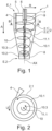
- Figure 1 shows a cyclone separator 1 in a first embodiment.
- the cyclone separator 1 has a peripheral wall 2, which is formed by a first wall section 2.1 and a second wall section 2.2 and defines a process chamber 3 centered around an axis AX and round in cross section.
- the first wall section 2.1 is cylindrical and is penetrated by a slot-shaped inlet nozzle 4. Furthermore, the first Wall section 2.1 is closed at a first end E.1 of the peripheral wall 2 by a cover 5.
- the cover 5 is penetrated by an outlet nozzle 6, which is arranged coaxially with the axis AX and has a dip tube 7, which projects from the cover 5 in an axial direction A into the process chamber 3.
- the axial direction A shown here corresponds to a previously referenced first direction.
- the second wall section 2.2 adjoins the first wall section 2.1 in the axial direction A and extends conically tapering to a second end E.2 of the peripheral wall 2. At the second end E.2, the second wall section 2.2 is closed by a solids outlet 8.
- the cyclone separator 1 also has a cylindrical guide means 11.1.
- the guide means 11.1 is designed, for example, as a guide rod or guide tube and extends coaxially to the axis AX through the entire process chamber 3.
- a helical trajectory 10 is created in a first region 10.1 for a process stream flowing in at the inlet nozzle 4.
- the first region 10.1 extends from the inlet nozzle 4 in the axial direction A to the second end E.2 of the peripheral wall 2 and is narrowed in the outer diameter of the helical shape by the second wall section 2.2. Solids and/or liquids contained in the mainly gaseous process stream are carried outwards in a radial direction R.
- the trajectory 10 At the second end E.2 of the peripheral wall 2, the trajectory 10 then has a deflection point 10.2 at which the process stream is deflected against the axial direction A and guided along a second region 10.3 to the outlet nozzle 6 or dip tube 7, whereby a helical trajectory still exists.
- the guiding means 11.1 also guides the process flow in the second area 10.3 of the trajectory 10 in its helix shape, so that the flow can develop there with reduced turbulence and a reduced pressure loss can be achieved. At the deflection point 10.2, the solids and/or liquids carried outwards can no longer follow the trajectory 10 due to their inertia and drop out.
- the pressure loss and the separation efficiency of the cyclone separator 1 are determined, among other things, by the ratio of the cross-sectional geometry of the guide means 11.1 and the cross-sectional geometry of the immersion tube 7.
- the guide means 11.1 is designed to be variable in its cross-section, as described below with regard to the Figures 3a to 5b will be explained in more detail.
- a diaphragm 9 is arranged in the immersion tube 7, the clear cross-section of which can be changed and by means of which, in addition to a guide means 11.1 whose cross-section can be changed, the ratio mentioned can be influenced in order to achieve an optimal compromise between low pressure loss and high separation efficiency for certain properties of a process stream.
- the diaphragm 9 is designed, for example, as an iris diaphragm.
- Figure 2 shows a cross section of Fig.1 according to section BB. It can be seen that the circumferential wall 2 is round in cross section and guides the first area 10.1 of the trajectory 10 in a helical shape. In the second area 10.3 of the trajectory 10, this is also helical along the guide means 11.1. Furthermore, an alignment of the inlet nozzle 4 in a circumferential direction U is shown.
- the Figures 3a and 3b show a first possible embodiment for a guide means 11.2 with a variable cross-section.
- the guide means 11.2 is designed as an elastic cylinder, for example made of an elastomer, and has a first threaded hole 12.1 at a first end E.1 and a second threaded hole 12.2 at a second end E.2. Screws 13.1, 13.2 engage in the threaded holes 12.1, 12.2, which are each supported on counter bearings 14.1, 14.2 connected to the cyclone separator 1. By turning the screws 13.1, 13.2, the guide means 11.2 can then be stretched or compressed between the counter bearings 14.1, 14.2.
- Figure 3b shows a first stretched contour 15.1, which results from a stretching of the guide means 11.2, and in which the cross section is constricted in particular in the axial direction A in the middle of the guide means 11.2 and thus reduced in size.
- Figure 3b also shows a first compressed contour 15.2, which which results from a compression of the guide means 11.2 and in which the cross-section is expanded and thus enlarged, particularly in the axial direction A in the middle of the guide means 11.2.
- the Figures 4a and 4b show a guide means 11.3 that largely corresponds to the guide means 11.2, whereby repeated descriptions are omitted.
- the guide means 11.3 is formed from a first section 16.1, a second section 16.2 and a third section 16.3, whereby the sections 16.1 and 16.3 have a different, namely lower, modulus of elasticity than the section 16.2.
- a second stretched contour 17.1 or a second compressed contour 17.2 is achieved, which have a cross-section that remains constant over the axial extent of the guide means 11.3, i.e. a uniform constriction or expansion.
- FIGS. 5a and 5b show yet another embodiment of a guide means 11.4, wherein the guide means 11.4 is designed as a guide tube with tube walls 18.1, 18.2 extending between the counter bearings 14.1, 14.2.
- the counter bearing 14.2 has an opening 19, via which an interior 18.3 of the guide means 11.4 is connected to a means 20 for supplying or removing air or other gas to or from the interior 18.3.
- the guide means 14.3 can be inflated or evacuated, whereby, as in Figure 5b shown, either an inflated contour 21.1 or an evacuated contour 21.2 of the pipe walls 18.1, 18.2 results.
Landscapes
- Cyclones (AREA)
Claims (15)
- Séparateur à cyclone (1) permettant la séparation de solides et/ou de liquides à partir d'un flux de processus, présentantune chambre de traitement (3) ronde en section transversale formée au moins par une paroi périphérique (2) et un couvercle (5) ;un orifice d'entrée (4) traversant la paroi périphérique (2) permettant l'entrée du flux de processus dans la chambre de traitement (3) dans la direction périphérique (U) de la chambre de traitement (3) ;un orifice de sortie (6) traversant le couvercle (5) permettant l'évacuation du flux de processus de la chambre de traitement (3) en direction axiale (A) de la chambre de traitement (3) ;un tube plongeur (7) s'étendant à partir de l'orifice de sortie (6) en direction axiale (A) vers l'intérieur de la chambre de traitement (3) ; etun moyen de guidage (11.1, 11.2, 11.3, 11.4) s'étendant en direction axiale (A) au centre de la chambre de traitement (3) et s'engageant dans le tube plongeur (7) ;caractérisé en ce que le moyen de guidage (11.1, 11.2, 11.3, 11.4) est conçu modifiable dans la section transversale au moins sur une partie de son extension axiale.
- Séparateur à cyclone (1) selon la revendication 1, dans lequel le moyen de guidage (11.1, 11.2, 11.3, 11.4) est conçu comme un tube de guidage.
- Séparateur à cyclone (1) selon la revendication 2, dans lequel le tube de guidage est conçu élastique et un espace intérieur (18.3) du tube de guidage est conçu modifiable en volume permettant la modification de la section transversale du tube de guidage.
- Séparateur à cyclone (1) selon la revendication 2 ou la revendication 3, dans lequel une paroi de tube (18.1, 18.2) du tube de guidage est conçue en forme de spirale.
- Séparateur à cyclone (1) selon l'une des revendications précédentes, dans lequel le moyen de guidage (11.1, 11.2, 11.3, 11.4) est conçu élastique et le séparateur à cyclone (1) présente des moyens permettant de plonger et/ou d'étirer le moyen de guidage (11.1, 11.2, 11.3, 11.4) pour la modification de la section transversale du moyen de guidage (11.1, 11.2, 11.3, 11.4).
- Séparateur à cyclone (1) selon la revendication 5, dans lequel le moyen de guidage (11.1, 11.2, 11.3, 11.4) présente au moins deux segments (16.1, 16.2, 16.3) le long de son extension axiale et dans lequel au moins deux segments (16.1, 16.2, 16.3) présentent des modules d'élasticité différents l'un de l'autre.
- Séparateur à cyclone (1) selon l'une des revendications précédentes, dans lequel le moyen de guidage (11.1, 11.2, 11.3, 11.4) présente plusieurs segments (16.1, 16.2, 16.3) le long de son extension axiale et au moins deux segments (16.1, 16.2, 16.3) sont conçus en pouvant coulisser l'un par rapport à l'autre, permettant la modification de la section transversale du moyen de guidage (11.1, 11.2, 11.3, 11.4) en direction axiale (A).
- Séparateur à cyclone (1) selon l'une des revendications précédentes, présentant des moyens permettant l'application d'une oscillation sur le moyen de guidage (11.1, 11.2, 11.3, 11.4) permettant la modification de la section transversale du moyen de guidage (11.1, 11.2, 11.3, 11.4).
- Séparateur à cyclone (1) selon l'une des revendications précédentes, dans lequel le tube plongeur (7) est conçu modifiable dans sa section transversale ou présente un diaphragme (9) avec une section transversale légèrement modifiable.
- Séparateur à cyclone (1) selon l'une des revendications précédentes, dans lequel le moyen de guidage (11.1, 11.2, 11.3, 11.4) est conçu dans une matière plastique, notamment à base d'un élastomère ou d'un thermoplastique.
- Séparateur à cyclone (1) selon l'une des revendications précédentes, dans lequel la paroi périphérique (2) est conçue conique au moins sur une partie de son extension axiale.
- Séparateur à cyclone (1) selon l'une des revendications précédentes, dans lequel l'orifice d'entrée (4) présente une extension en forme de fente dans la direction axiale (A) de la chambre de traitement (3).
- Séparateur à cyclone (1) selon l'une des revendications précédentes, présentant une sortie de solide (8) disposée à une extrémité (E.2) de la chambre de traitement permettant l'évacuation de solide de la chambre de traitement (3).
- Procédé de mise en oeuvre d'un séparateur à cyclone (1) selon l'une des revendications précédentes, dans lequel la section transversale du moyen de guidage (11.1, 11.2, 11.3, 11.4) est modifiée au moins dans une partie de l'extension axiale du moyen de guidage (11.1, 11.2, 11.3, 11.4) en fonction d'un flux massique, d'une vitesse d'écoulement, d'une charges en solides ou d'une charge en liquides du flux de processus.
- Système de séparateur à cyclone présentant un séparateur à cyclone (1) selon l'une des revendications 1 à 13 ainsi qu'au moins un capteur permettant la détection d'un flux massique, d'une vitesse d'écoulement, d'une charges en solides ou d'une charge en liquides du flux de processus.
Priority Applications (7)
| Application Number | Priority Date | Filing Date | Title |
|---|---|---|---|
| EP22170817.5A EP4268968B1 (fr) | 2022-04-29 | 2022-04-29 | Séparateur à cyclone permettant de séparer des solides et/ou des liquides d'un flux de processus |
| CA3256817A CA3256817A1 (fr) | 2022-04-29 | 2023-04-26 | Séparateur cyclone pour séparer des solides et/ou des liquides d’un flux de traitement |
| EP23721936.5A EP4460400A1 (fr) | 2022-04-29 | 2023-04-26 | Séparateur cyclone pour séparer des solides et/ou des liquides d'un flux de traitement |
| PCT/EP2023/060897 WO2023208989A1 (fr) | 2022-04-29 | 2023-04-26 | Séparateur cyclone pour séparer des solides et/ou des liquides d'un flux de traitement |
| US18/857,811 US20250296094A1 (en) | 2022-04-29 | 2023-04-26 | Cyclone Separator For Separating Solids and/or Liquids From a Process Stream |
| CN202380019075.1A CN118574678A (zh) | 2022-04-29 | 2023-04-26 | 用于从工艺流中分离固体和/或液体的旋风分离器 |
| MX2024013128A MX2024013128A (es) | 2022-04-29 | 2024-10-24 | Separador ciclonico para separar solidos y/o liquidos de un flujo de proceso |
Applications Claiming Priority (1)
| Application Number | Priority Date | Filing Date | Title |
|---|---|---|---|
| EP22170817.5A EP4268968B1 (fr) | 2022-04-29 | 2022-04-29 | Séparateur à cyclone permettant de séparer des solides et/ou des liquides d'un flux de processus |
Publications (3)
| Publication Number | Publication Date |
|---|---|
| EP4268968A1 EP4268968A1 (fr) | 2023-11-01 |
| EP4268968C0 EP4268968C0 (fr) | 2024-08-07 |
| EP4268968B1 true EP4268968B1 (fr) | 2024-08-07 |
Family
ID=81448259
Family Applications (1)
| Application Number | Title | Priority Date | Filing Date |
|---|---|---|---|
| EP22170817.5A Active EP4268968B1 (fr) | 2022-04-29 | 2022-04-29 | Séparateur à cyclone permettant de séparer des solides et/ou des liquides d'un flux de processus |
Country Status (2)
| Country | Link |
|---|---|
| EP (1) | EP4268968B1 (fr) |
| CN (1) | CN118574678A (fr) |
Family Cites Families (1)
| Publication number | Priority date | Publication date | Assignee | Title |
|---|---|---|---|---|
| US6312594B1 (en) * | 1998-08-19 | 2001-11-06 | G.B.D. Corp. | Insert for a cyclone separator |
-
2022
- 2022-04-29 EP EP22170817.5A patent/EP4268968B1/fr active Active
-
2023
- 2023-04-26 CN CN202380019075.1A patent/CN118574678A/zh active Pending
Also Published As
| Publication number | Publication date |
|---|---|
| EP4268968A1 (fr) | 2023-11-01 |
| EP4268968C0 (fr) | 2024-08-07 |
| CN118574678A (zh) | 2024-08-30 |
Similar Documents
| Publication | Publication Date | Title |
|---|---|---|
| DE69129151T2 (de) | Hochleistungsfähiger flüssigkeit/flüssigkeit-hydrozyklon | |
| EP3117904B1 (fr) | Dispositif de separation pour de petites parties d'un flux de fluide | |
| DE19644447C2 (de) | Verfahren und Vorrichtung zur kontinuierlichen Extrusion von mit einem wendelförmigen Innenkanal ausgestatteten Stäben aus plastischem Rohmaterial | |
| DE2656151C2 (de) | Vorrichtung zum Abtrennen von Festkörperverunreinigungen aus einem Gasstrom | |
| DE3717128C2 (fr) | ||
| DE102009057079A1 (de) | Hydrozyklonanordnung, Unterlaufdüse mit Ansatz- oder Verlängerungsstück für einen Hydrozyklon sowie Verfahren zum Betreiben einer Hydrozyklonanordnung | |
| EP3183052B1 (fr) | Procédé et dispositif pour épurer des suspensions de matières fibreuses par flottation | |
| DE202016103608U1 (de) | Filtervorrichtung und Reinigungseinrichtung zum Entfernen von Schmutzpartikeln von einem Filterelement einer Filtervorrichtung Filtervorrichtung und Reinigungseinrichtung zum Entfernen von Schmutzpartikeln von einem Filterelement einer Filtervorrichtung | |
| DE102017213608B4 (de) | Gleichstromzyklonabscheider | |
| WO2014086735A2 (fr) | Buse d'évacuation d'un tambour centrifuge | |
| DE4214771C2 (de) | Verfahren und Vorrichtung zum Naßklassieren | |
| DE102022110536B3 (de) | Zyklonabscheider zum Abscheiden von Feststoffen und/oder Flüssigkeiten aus einem Prozessstrom | |
| EP4268968A1 (fr) | Séparateur à cyclone permettant de séparer des solides et/ou des liquides d'un flux de processus | |
| WO2023208989A1 (fr) | Séparateur cyclone pour séparer des solides et/ou des liquides d'un flux de traitement | |
| EP0662348B1 (fr) | Séparateur centrifuge avec dispositif de régulation | |
| EP1799903A1 (fr) | Procede pour fractionner une suspension aqueuse de fibres a papier et hydrocyclone pour la mise en oeuvre dudit procede | |
| DD300816A5 (de) | Verfahren und vorrichtung zum abtrennen von stoffen aus einem medium | |
| EP1191141A1 (fr) | Hydrocyclone | |
| EP4268967A1 (fr) | Séparateur à cyclone permettant de séparer des solides d'un écoulement de processus | |
| EP1259304A1 (fr) | Dispositif filtre | |
| DE2903733A1 (de) | Duese fuer hochdruckfluessigkeit | |
| DE102008029203A1 (de) | Vorrichtung zur Medientrennung | |
| DE10205210B4 (de) | Vorrichtung zur Herstellung von Kunststoffrohren | |
| EP0882514B1 (fr) | Dispositif de séparation | |
| EP1876289A1 (fr) | Procédé destiné à la séparation d'impuretés d'une suspension fibreuse |
Legal Events
| Date | Code | Title | Description |
|---|---|---|---|
| PUAI | Public reference made under article 153(3) epc to a published international application that has entered the european phase |
Free format text: ORIGINAL CODE: 0009012 |
|
| STAA | Information on the status of an ep patent application or granted ep patent |
Free format text: STATUS: THE APPLICATION HAS BEEN PUBLISHED |
|
| AK | Designated contracting states |
Kind code of ref document: A1 Designated state(s): AL AT BE BG CH CY CZ DE DK EE ES FI FR GB GR HR HU IE IS IT LI LT LU LV MC MK MT NL NO PL PT RO RS SE SI SK SM TR |
|
| STAA | Information on the status of an ep patent application or granted ep patent |
Free format text: STATUS: REQUEST FOR EXAMINATION WAS MADE |
|
| 17P | Request for examination filed |
Effective date: 20240408 |
|
| RBV | Designated contracting states (corrected) |
Designated state(s): AL AT BE BG CH CY CZ DE DK EE ES FI FR GB GR HR HU IE IS IT LI LT LU LV MC MK MT NL NO PL PT RO RS SE SI SK SM TR |
|
| GRAP | Despatch of communication of intention to grant a patent |
Free format text: ORIGINAL CODE: EPIDOSNIGR1 |
|
| STAA | Information on the status of an ep patent application or granted ep patent |
Free format text: STATUS: GRANT OF PATENT IS INTENDED |
|
| INTG | Intention to grant announced |
Effective date: 20240522 |
|
| GRAS | Grant fee paid |
Free format text: ORIGINAL CODE: EPIDOSNIGR3 |
|
| GRAA | (expected) grant |
Free format text: ORIGINAL CODE: 0009210 |
|
| STAA | Information on the status of an ep patent application or granted ep patent |
Free format text: STATUS: THE PATENT HAS BEEN GRANTED |
|
| AK | Designated contracting states |
Kind code of ref document: B1 Designated state(s): AL AT BE BG CH CY CZ DE DK EE ES FI FR GB GR HR HU IE IS IT LI LT LU LV MC MK MT NL NO PL PT RO RS SE SI SK SM TR |
|
| REG | Reference to a national code |
Ref country code: GB Ref legal event code: FG4D Free format text: NOT ENGLISH |
|
| REG | Reference to a national code |
Ref country code: CH Ref legal event code: EP |
|
| REG | Reference to a national code |
Ref country code: IE Ref legal event code: FG4D Free format text: LANGUAGE OF EP DOCUMENT: GERMAN |
|
| REG | Reference to a national code |
Ref country code: DE Ref legal event code: R096 Ref document number: 502022001389 Country of ref document: DE |
|
| U01 | Request for unitary effect filed |
Effective date: 20240807 |
|
| U07 | Unitary effect registered |
Designated state(s): AT BE BG DE DK EE FI FR IT LT LU LV MT NL PT SE SI Effective date: 20240814 |
|
| PG25 | Lapsed in a contracting state [announced via postgrant information from national office to epo] |
Ref country code: NO Free format text: LAPSE BECAUSE OF FAILURE TO SUBMIT A TRANSLATION OF THE DESCRIPTION OR TO PAY THE FEE WITHIN THE PRESCRIBED TIME-LIMIT Effective date: 20241107 |
|
| PG25 | Lapsed in a contracting state [announced via postgrant information from national office to epo] |
Ref country code: PL Free format text: LAPSE BECAUSE OF FAILURE TO SUBMIT A TRANSLATION OF THE DESCRIPTION OR TO PAY THE FEE WITHIN THE PRESCRIBED TIME-LIMIT Effective date: 20240807 Ref country code: GR Free format text: LAPSE BECAUSE OF FAILURE TO SUBMIT A TRANSLATION OF THE DESCRIPTION OR TO PAY THE FEE WITHIN THE PRESCRIBED TIME-LIMIT Effective date: 20241108 |
|
| PG25 | Lapsed in a contracting state [announced via postgrant information from national office to epo] |
Ref country code: IS Free format text: LAPSE BECAUSE OF FAILURE TO SUBMIT A TRANSLATION OF THE DESCRIPTION OR TO PAY THE FEE WITHIN THE PRESCRIBED TIME-LIMIT Effective date: 20241207 |
|
| PG25 | Lapsed in a contracting state [announced via postgrant information from national office to epo] |
Ref country code: HR Free format text: LAPSE BECAUSE OF FAILURE TO SUBMIT A TRANSLATION OF THE DESCRIPTION OR TO PAY THE FEE WITHIN THE PRESCRIBED TIME-LIMIT Effective date: 20240807 |
|
| PG25 | Lapsed in a contracting state [announced via postgrant information from national office to epo] |
Ref country code: RS Free format text: LAPSE BECAUSE OF FAILURE TO SUBMIT A TRANSLATION OF THE DESCRIPTION OR TO PAY THE FEE WITHIN THE PRESCRIBED TIME-LIMIT Effective date: 20241107 Ref country code: ES Free format text: LAPSE BECAUSE OF FAILURE TO SUBMIT A TRANSLATION OF THE DESCRIPTION OR TO PAY THE FEE WITHIN THE PRESCRIBED TIME-LIMIT Effective date: 20240807 |
|
| PG25 | Lapsed in a contracting state [announced via postgrant information from national office to epo] |
Ref country code: RS Free format text: LAPSE BECAUSE OF FAILURE TO SUBMIT A TRANSLATION OF THE DESCRIPTION OR TO PAY THE FEE WITHIN THE PRESCRIBED TIME-LIMIT Effective date: 20241107 Ref country code: PL Free format text: LAPSE BECAUSE OF FAILURE TO SUBMIT A TRANSLATION OF THE DESCRIPTION OR TO PAY THE FEE WITHIN THE PRESCRIBED TIME-LIMIT Effective date: 20240807 Ref country code: NO Free format text: LAPSE BECAUSE OF FAILURE TO SUBMIT A TRANSLATION OF THE DESCRIPTION OR TO PAY THE FEE WITHIN THE PRESCRIBED TIME-LIMIT Effective date: 20241107 Ref country code: IS Free format text: LAPSE BECAUSE OF FAILURE TO SUBMIT A TRANSLATION OF THE DESCRIPTION OR TO PAY THE FEE WITHIN THE PRESCRIBED TIME-LIMIT Effective date: 20241207 Ref country code: HR Free format text: LAPSE BECAUSE OF FAILURE TO SUBMIT A TRANSLATION OF THE DESCRIPTION OR TO PAY THE FEE WITHIN THE PRESCRIBED TIME-LIMIT Effective date: 20240807 Ref country code: GR Free format text: LAPSE BECAUSE OF FAILURE TO SUBMIT A TRANSLATION OF THE DESCRIPTION OR TO PAY THE FEE WITHIN THE PRESCRIBED TIME-LIMIT Effective date: 20241108 Ref country code: ES Free format text: LAPSE BECAUSE OF FAILURE TO SUBMIT A TRANSLATION OF THE DESCRIPTION OR TO PAY THE FEE WITHIN THE PRESCRIBED TIME-LIMIT Effective date: 20240807 |
|
| PG25 | Lapsed in a contracting state [announced via postgrant information from national office to epo] |
Ref country code: SM Free format text: LAPSE BECAUSE OF FAILURE TO SUBMIT A TRANSLATION OF THE DESCRIPTION OR TO PAY THE FEE WITHIN THE PRESCRIBED TIME-LIMIT Effective date: 20240807 |
|
| PG25 | Lapsed in a contracting state [announced via postgrant information from national office to epo] |
Ref country code: CZ Free format text: LAPSE BECAUSE OF FAILURE TO SUBMIT A TRANSLATION OF THE DESCRIPTION OR TO PAY THE FEE WITHIN THE PRESCRIBED TIME-LIMIT Effective date: 20240807 |
|
| PG25 | Lapsed in a contracting state [announced via postgrant information from national office to epo] |
Ref country code: SK Free format text: LAPSE BECAUSE OF FAILURE TO SUBMIT A TRANSLATION OF THE DESCRIPTION OR TO PAY THE FEE WITHIN THE PRESCRIBED TIME-LIMIT Effective date: 20240807 |
|
| U20 | Renewal fee for the european patent with unitary effect paid |
Year of fee payment: 4 Effective date: 20250408 |
|
| PLBE | No opposition filed within time limit |
Free format text: ORIGINAL CODE: 0009261 |
|
| STAA | Information on the status of an ep patent application or granted ep patent |
Free format text: STATUS: NO OPPOSITION FILED WITHIN TIME LIMIT |
|
| 26N | No opposition filed |
Effective date: 20250508 |
|
| REG | Reference to a national code |
Ref country code: CH Ref legal event code: H13 Free format text: ST27 STATUS EVENT CODE: U-0-0-H10-H13 (AS PROVIDED BY THE NATIONAL OFFICE) Effective date: 20251125 |
|
| PG25 | Lapsed in a contracting state [announced via postgrant information from national office to epo] |
Ref country code: MC Free format text: LAPSE BECAUSE OF FAILURE TO SUBMIT A TRANSLATION OF THE DESCRIPTION OR TO PAY THE FEE WITHIN THE PRESCRIBED TIME-LIMIT Effective date: 20240807 |
|
| PG25 | Lapsed in a contracting state [announced via postgrant information from national office to epo] |
Ref country code: CH Free format text: LAPSE BECAUSE OF NON-PAYMENT OF DUE FEES Effective date: 20250430 |
|
| U1N | Appointed representative for the unitary patent procedure changed after the registration of the unitary effect |
Representative=s name: AURODION PARTMBB; DE |
|
| PG25 | Lapsed in a contracting state [announced via postgrant information from national office to epo] |
Ref country code: IE Free format text: LAPSE BECAUSE OF NON-PAYMENT OF DUE FEES Effective date: 20250429 |
|
| PG25 | Lapsed in a contracting state [announced via postgrant information from national office to epo] |
Ref country code: RO Free format text: LAPSE BECAUSE OF FAILURE TO SUBMIT A TRANSLATION OF THE DESCRIPTION OR TO PAY THE FEE WITHIN THE PRESCRIBED TIME-LIMIT Effective date: 20240807 |
|
| U20 | Renewal fee for the european patent with unitary effect paid |
Year of fee payment: 5 Effective date: 20260407 |