EP4268971B1 - Adaptateur angulaire pour un dispositif de pulvérisation de poudre - Google Patents
Adaptateur angulaire pour un dispositif de pulvérisation de poudre Download PDFInfo
- Publication number
- EP4268971B1 EP4268971B1 EP22169629.7A EP22169629A EP4268971B1 EP 4268971 B1 EP4268971 B1 EP 4268971B1 EP 22169629 A EP22169629 A EP 22169629A EP 4268971 B1 EP4268971 B1 EP 4268971B1
- Authority
- EP
- European Patent Office
- Prior art keywords
- angle adapter
- powder
- housing
- adapter according
- case
- Prior art date
- Legal status (The legal status is an assumption and is not a legal conclusion. Google has not performed a legal analysis and makes no representation as to the accuracy of the status listed.)
- Active
Links
Images






Classifications
-
- B—PERFORMING OPERATIONS; TRANSPORTING
- B05—SPRAYING OR ATOMISING IN GENERAL; APPLYING FLUENT MATERIALS TO SURFACES, IN GENERAL
- B05B—SPRAYING APPARATUS; ATOMISING APPARATUS; NOZZLES
- B05B13/00—Machines or plants for applying liquids or other fluent materials to surfaces of objects or other work by spraying, not covered by groups B05B1/00 - B05B11/00
- B05B13/02—Means for supporting work; Arrangement or mounting of spray heads; Adaptation or arrangement of means for feeding work
- B05B13/0278—Arrangement or mounting of spray heads
-
- B—PERFORMING OPERATIONS; TRANSPORTING
- B05—SPRAYING OR ATOMISING IN GENERAL; APPLYING FLUENT MATERIALS TO SURFACES, IN GENERAL
- B05B—SPRAYING APPARATUS; ATOMISING APPARATUS; NOZZLES
- B05B15/00—Details of spraying plant or spraying apparatus not otherwise provided for; Accessories
- B05B15/60—Arrangements for mounting, supporting or holding spraying apparatus
- B05B15/65—Mounting arrangements for fluid connection of the spraying apparatus or its outlets to flow conduits
- B05B15/652—Mounting arrangements for fluid connection of the spraying apparatus or its outlets to flow conduits whereby the jet can be oriented
-
- B—PERFORMING OPERATIONS; TRANSPORTING
- B05—SPRAYING OR ATOMISING IN GENERAL; APPLYING FLUENT MATERIALS TO SURFACES, IN GENERAL
- B05B—SPRAYING APPARATUS; ATOMISING APPARATUS; NOZZLES
- B05B5/00—Electrostatic spraying apparatus; Spraying apparatus with means for charging the spray electrically; Apparatus for spraying liquids or other fluent materials by other electric means
- B05B5/025—Discharge apparatus, e.g. electrostatic spray guns
- B05B5/04—Discharge apparatus, e.g. electrostatic spray guns characterised by having rotary outlet or deflecting elements, i.e. spraying being also effected by centrifugal forces
- B05B5/0418—Discharge apparatus, e.g. electrostatic spray guns characterised by having rotary outlet or deflecting elements, i.e. spraying being also effected by centrifugal forces designed for spraying particulate material
-
- B—PERFORMING OPERATIONS; TRANSPORTING
- B05—SPRAYING OR ATOMISING IN GENERAL; APPLYING FLUENT MATERIALS TO SURFACES, IN GENERAL
- B05B—SPRAYING APPARATUS; ATOMISING APPARATUS; NOZZLES
- B05B15/00—Details of spraying plant or spraying apparatus not otherwise provided for; Accessories
- B05B15/60—Arrangements for mounting, supporting or holding spraying apparatus
- B05B15/68—Arrangements for adjusting the position of spray heads
-
- B—PERFORMING OPERATIONS; TRANSPORTING
- B05—SPRAYING OR ATOMISING IN GENERAL; APPLYING FLUENT MATERIALS TO SURFACES, IN GENERAL
- B05B—SPRAYING APPARATUS; ATOMISING APPARATUS; NOZZLES
- B05B5/00—Electrostatic spraying apparatus; Spraying apparatus with means for charging the spray electrically; Apparatus for spraying liquids or other fluent materials by other electric means
- B05B5/025—Discharge apparatus, e.g. electrostatic spray guns
- B05B5/03—Discharge apparatus, e.g. electrostatic spray guns characterised by the use of gas, e.g. electrostatically assisted pneumatic spraying
-
- B—PERFORMING OPERATIONS; TRANSPORTING
- B05—SPRAYING OR ATOMISING IN GENERAL; APPLYING FLUENT MATERIALS TO SURFACES, IN GENERAL
- B05B—SPRAYING APPARATUS; ATOMISING APPARATUS; NOZZLES
- B05B5/00—Electrostatic spraying apparatus; Spraying apparatus with means for charging the spray electrically; Apparatus for spraying liquids or other fluent materials by other electric means
- B05B5/025—Discharge apparatus, e.g. electrostatic spray guns
- B05B5/03—Discharge apparatus, e.g. electrostatic spray guns characterised by the use of gas, e.g. electrostatically assisted pneumatic spraying
- B05B5/032—Discharge apparatus, e.g. electrostatic spray guns characterised by the use of gas, e.g. electrostatically assisted pneumatic spraying for spraying particulate materials
-
- B—PERFORMING OPERATIONS; TRANSPORTING
- B05—SPRAYING OR ATOMISING IN GENERAL; APPLYING FLUENT MATERIALS TO SURFACES, IN GENERAL
- B05B—SPRAYING APPARATUS; ATOMISING APPARATUS; NOZZLES
- B05B5/00—Electrostatic spraying apparatus; Spraying apparatus with means for charging the spray electrically; Apparatus for spraying liquids or other fluent materials by other electric means
- B05B5/025—Discharge apparatus, e.g. electrostatic spray guns
- B05B5/043—Discharge apparatus, e.g. electrostatic spray guns using induction-charging
-
- B—PERFORMING OPERATIONS; TRANSPORTING
- B05—SPRAYING OR ATOMISING IN GENERAL; APPLYING FLUENT MATERIALS TO SURFACES, IN GENERAL
- B05B—SPRAYING APPARATUS; ATOMISING APPARATUS; NOZZLES
- B05B5/00—Electrostatic spraying apparatus; Spraying apparatus with means for charging the spray electrically; Apparatus for spraying liquids or other fluent materials by other electric means
- B05B5/025—Discharge apparatus, e.g. electrostatic spray guns
- B05B5/053—Arrangements for supplying power, e.g. charging power
- B05B5/0533—Electrodes specially adapted therefor; Arrangements of electrodes
-
- B—PERFORMING OPERATIONS; TRANSPORTING
- B05—SPRAYING OR ATOMISING IN GENERAL; APPLYING FLUENT MATERIALS TO SURFACES, IN GENERAL
- B05B—SPRAYING APPARATUS; ATOMISING APPARATUS; NOZZLES
- B05B5/00—Electrostatic spraying apparatus; Spraying apparatus with means for charging the spray electrically; Apparatus for spraying liquids or other fluent materials by other electric means
- B05B5/16—Arrangements for supplying liquids or other fluent material
- B05B5/1683—Arrangements for supplying liquids or other fluent material specially adapted for particulate materials
Definitions
- the invention relates to an angle adapter for a powder spraying device for spraying coating powder.
- the workpiece to be coated is covered with a layer of powder using a powder spray applicator.
- the powder-coated workpiece is then heated until the powder melts and forms a closed layer. After the layer has cooled, it forms a closed protective layer that adheres firmly to the workpiece.
- a suitable powder spray applicator has a powder-carrying line that opens into a powder spray nozzle on the outlet side. The coating powder to be sprayed is sprayed through the powder spray nozzle.
- the spray direction of the powder spray applicator In order to achieve an optimal coating of the workpiece, it is generally recommended to adapt the spray direction of the powder spray applicator to the geometry of the workpiece to be coated. If the powder spray applicator only sprays the powder forwards in the longitudinal direction, it may happen that certain areas of certain workpieces cannot be sprayed sufficiently. This is the case, for example, if the workpiece has an interior space whose surface can only be covered by a spray gun that is aligned in the longitudinal direction. Powder jet cannot be sprayed or cannot be sprayed sufficiently.
- an angle adapter can be provided on the downstream side of the spray applicator. This allows the powder spray direction to be changed so that the spray direction no longer runs in the longitudinal direction, but is pivoted at a defined angle to the longitudinal direction. In the following, this angle is referred to as the pivot angle.
- the Inogun A operating manual from Sames Kremlin ( https://www.manualslib.de/manual/730827/Sames-Kremlin-Inogun-A-Fcc.html#manual ) describes a powder spray gun for spraying coating powder that can be equipped with such an angle adapter.
- the angle adapter is available in two versions, namely as a so-called 60° nozzle adapter and as a 90° nozzle adapter.
- the spray jet is swiveled at a swivel angle of 60° relative to the longitudinal axis.
- the nozzle adapter can be rotated around the longitudinal axis of the gun barrel.
- Document DE 20 2012 004571 U1 shows a tube sleeve for tribostatically charging a paint powder which is carried in a gas stream flowing along a longitudinal axis of the tube sleeve, wherein the tube sleeve comprises an end piece with at least one section widening on the outflow side to form an annular gap, wherein the tube sleeve has a plurality of rotary flow bores, wherein the rotary flow bores are arranged to introduce a gas applied on the outside in the same direction as the flow direction at an acute angle to the inner surface of the tube sleeve.
- An object of the invention is to provide an angle adapter for a powder spraying device in which not only the angle of rotation but also the swivel angle of the powder spraying direction is adjustable.
- the angle adapter according to the invention ensures that the high voltage can always be guided to the nozzle or to the high-voltage electrode, regardless of the set spray direction.
- the angle adapter according to the invention also ensures that gas which is to flow around the high-voltage electrode can always be guided to the high-voltage electrode, regardless of the set spray direction.
- the angle adapter according to the invention for a powder spray device comprises an upstream housing which has an upstream powder channel, a connection to the powder spray device and a longitudinal axis about which the housing can be rotated.
- the powder spray device comprises a pivoting body with a downstream powder channel which is connected to the upstream powder channel.
- the pivoting body can be pivoted about a pivot axis, wherein the pivot axis runs obliquely to the longitudinal axis.
- the angle adapter has a high-voltage line which extends from the upstream housing via the pivoting body to the nozzle and is designed there as a high-voltage electrode.
- the powder channel is designed such that the upstream powder channel tapers in the direction of flow and the downstream powder channel widens. This makes it possible for the powder flowing through the angled area of the powder channel to be distributed more homogeneously in the downstream powder channel.
- a gas line is provided in which part of the gas line runs through the upstream housing and another part of the gas line runs through the swivel body.
- the gas line is provided to transport gas to the high-voltage electrode or to the nozzle. This enables a particularly compact design.
- the part of the gas line arranged in the housing is connected to the labyrinth on the outlet side. This also enables a particularly compact design. And if ozone or ionized air forms in the labyrinth, it can be flushed out with the gas transported into the labyrinth.
- the part of the gas line arranged in the swivel body is connected to the labyrinth on the inlet side. This also enables a particularly compact design.
- the gas line can be used to flush out the labyrinth and to transport the gas to the high-voltage electrode.
- a dielectric is provided in the labyrinth. This allows the electrical insulation to be increased towards the outside of the angle adapter.
- the dielectric is an inert gas or high-voltage grease.
- angle adapter according to the invention can be provided with the downstream powder channel having a longitudinal axis which runs obliquely to the pivot axis.
- the upstream powder channel has a downstream channel section and an upstream channel section.
- the upstream channel section runs concentrically to the longitudinal axis and the downstream channel section runs concentrically to the pivot axis.
- a contact ring is provided at the transition from the upstream housing to the swivel body.
- the contact ring serves to connect the part of the high-voltage line located in the upstream housing with the part of the high-voltage line located in the swivel body.
- the contact ring is arranged adjacent to the powder channel.
- the contact ring is arranged between the powder channel and the gas line, viewed in the radial direction.
- angle adapter in the outer area of the transition from A seal is provided between the housing and the swivel body, which seals the labyrinth gas-tight to the outside.
- the angle adapter according to the invention can have a clamping nut which is arranged at the transition from the housing to the swivel body and is intended to fasten the swivel body to the housing.
- the clamping nut is made of an electrically non-conductive material.
- the labyrinth in the angle adapter according to the invention preferably has a width of between 0.1 mm and 0.8 mm.
- the width refers to the width of the gap within the labyrinth through which gas, for example compressed air, can flow.
- the outlet of the upstream powder channel and the inlet of the downstream powder channel are designed such that they can be tightly connected to one another.
- a powder mixer can be provided in the upstream area of the downstream powder channel. This has the advantage that the powder is distributed more homogeneously in the powder channel.
- the cross-section of the powder mixer viewed in the direction of flow, first tapers and later widens again.
- the powder mixer has blades in order to give the powder flowing through the powder channel a swirl.
- the contact ring in the angle adapter is designed as a conductive O-ring.
- This O-ring can also be provided to seal the labyrinth in the radial direction towards the powder channel.
- the angle adapter according to the invention can have a threaded sleeve via which the housing can be connected to a gun barrel.
- the threaded sleeve is designed in such a way that, when released, it enables the angle adapter to be rotated relative to the gun barrel.
- a method for setting the direction in which a powder spray device is to spray which comprises the angle adapter described above.
- the method comprises the following steps. A clamping nut connecting the housing and the swivel body is loosened. In a further step, the swivel body is swiveled relative to the housing into the desired swivel angle position. In an additional step, the clamping nut is screwed tight.
- the method may additionally include the following steps.
- the threaded sleeve connecting the housing to the gun barrel is loosened.
- the angle adapter is turned to the desired position opposite the gun barrel and the threaded sleeve is screwed on.
- the angle adapter comprises a housing 1, which is also referred to as the upstream housing, and a swivel body 3 which is connected to the housing 1 on the downstream side thereof.
- the housing 1 has a longitudinal axis LA1, the swivel body 3 has its own longitudinal axis LA2.
- the longitudinal axis LA1 is also referred to below as the first longitudinal axis and the longitudinal axis LA2 is also referred to as the second longitudinal axis.
- a powder channel 2 is located inside the housing 1.
- a powder channel 42 is connected to the downstream end of the powder channel 2, with the two powder channels 2 and 42 preferably being arranged concentrically to the longitudinal axis LA1.
- the downstream end of the powder channel 42 is rotatably connected to a powder channel 41.
- the powder channel 41 is arranged concentrically to the pivot axis DA and this is inclined at an angle ⁇ to the longitudinal axis LA1.
- the pivot axis DA therefore runs obliquely to the longitudinal axis LA1, with the angle ⁇ defining how obliquely the pivot axis DA runs to the longitudinal axis LA1.
- a downstream powder channel 4 is connected to the powder channel 41.
- the powder channel 4 is arranged in an electrode holder 35 and extends through it.
- the powder channel 4 is preferably arranged concentrically to the second longitudinal axis LA2.
- the longitudinal axis LA2 is inclined relative to the pivot axis DA by an angle ⁇ .
- the longitudinal axis LA2 therefore runs obliquely to the pivot axis DA, with the angle ⁇ defining how obliquely the longitudinal axis LA2 runs relative to the pivot axis DA.
- a powder nozzle 5 is connected to the powder channel 4, through which the powder P can be sprayed.
- the nozzle 5 can also be arranged concentrically to the second longitudinal axis LA2.
- the angle ⁇ can be, for example, 135°.
- the angle ⁇ can also be, for example, 135°.
- the two angles ⁇ and ⁇ are preferably equal, so that the two longitudinal axes LA1 and LA2 run parallel to each other (see Fig. 3 ). If the two angles ⁇ and ⁇ are each 135°, the longitudinal axis LA2 can form an angle of 0° to a maximum of 90° with the longitudinal axis LA1 (see Fig. 3 and 9 ).
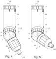
- the angle adapter is shown in a first powder spraying position.
- the first longitudinal axis LA1 and the second longitudinal axis LA2 are offset parallel to one another.
- the powder spraying direction is offset parallel to the first longitudinal axis LA1, so that the powder P is sprayed out of the nozzle 11 offset parallel to the first longitudinal axis LA1.
- the angle adapter is shown in a third powder spraying position.
- the size of the set swivel angle ⁇ can be read off using a scale 22 on the housing 1 in conjunction with a mark 23 that is attached to the swivel body 3.
- the swivel body 3 has several webs 6 and grooves 7 where it is in contact with the housing 1.
- the housing 1 also has grooves 19 and webs 18 where it is in contact with the swivel body 3. This area forms the transition between the housing 1 and the swivel body 3.
- the grooves 19 and webs 18 of the housing 1 and the webs 6 and grooves 7 of the swivel body 3 are designed and arranged in such a way that a web 6 of the swivel body 3 projects into a groove 19 of the housing 1 and a web 18 of the housing 1 projects into a groove 7 of the swivel body 3.
- the webs 6, 18 and grooves 7, 19 form a joint with which the swivel body 3 can be swiveled relative to the housing 1.
- the surface 14 on the housing 1 forms a support surface on which the swivel body 3 rests movably ( Figure 7 ).
- the two straight lines 30 and 31 are selected so that they lie in the support surface 14. They span the swivel plane.
- the swivel axis DA is perpendicular to the swivel plane.
- the interface which is part of the joint on the housing 1, can have (for example on the outside) one or more locking lugs 1.13 (see Figure 7 and 8 ).
- the swivel body 3 can also have one or more locking lugs 3.13 in the area of the interface. This allows the swivel angle ⁇ to be changed in angular steps specified by the locking lugs 1.13 and 3.13.
- the locking lugs 1.13 and 3.13 engage with each other, the swivel body 3 is prevented from being accidentally swiveled relative to the housing 1.
- the O-ring 39 which makes the electrical contact between the two high-voltage lines 10.1 and 10.2, is also protected in this way. Otherwise the wire end of the high-voltage line 10.1 or the wire end 12 of the high-voltage line 10.2 could damage the O-ring 39.
- the locking mechanism prevents the possibly sharp wire end 12 from being pulled over the O-ring 39.
- clamping nut 15 there is a clamping nut 15 on the joint.
- the clamping nut 15 When the clamping nut 15 is loosened, the swivel body 3 can be swiveled relative to the housing 1.
- the clamping nut 15 When the clamping nut 15 is tightened, however, the swivel body 3 and the housing 1 are rigidly connected to one another. This prevents the swivel body 3 from being accidentally swiveled relative to the housing 1.
- the clamping nut 15 also ensures that the swivel body 3 cannot fall off the housing 1.
- the clamping nut 15 extends the path for the high voltage. This means that the high voltage that is guided inside the angle adapter on the high-voltage line 10 has to travel a greater distance before it reaches the outside of the angle adapter.
- the webs 6, 18 and grooves 7, 19 are designed such that the webs 6, 18 protrude into the grooves 7, 19 without touching the grooves 7, 19.
- the space between the webs 6 and the grooves 19 or the webs 18 and the grooves 7 forms a labyrinth 8.
- the labyrinth 8 is intended to increase the distance between the high-voltage line 10 and the outside of the angle adapter. This reduces the risk of an electrical discharge.
- the space or the labyrinth can be filled with a dielectric.
- a dielectric here is an electrically weakly or non-conductive substance in which the existing charge carriers cannot move freely.
- the dielectric can be an inert gas or high-voltage grease and has the purpose of increasing the electrical insulation between the high-voltage electrode 10 carrying the high voltage and the outside of the powder spray device.
- the O-ring 39 can be designed as an electrically conductive ring and form the electrical contact point between the housing 1 and the swivel body 3 for the high voltage. This ensures that the high-voltage line 10.2 in the swivel body 3 and the high-voltage line 10.1 in the housing 1 are always connected to one another, regardless of how the swivel body 3 is swiveled relative to the housing 1.
- the O-ring 39 can also be provided to seal the labyrinth 8 in a radial direction inwards, towards the powder channel 2.
- the O-ring 16 serves to seal the labyrinth 8 in the radial outward direction.
- the labyrinth 8 is not a gas-tight space but is to be traversed by a fluid, for example, ordinary air under pressure (compressed air) can be used instead of the dielectric.
- a fluid for example, ordinary air under pressure (compressed air) can be used instead of the dielectric.
- the labyrinth 8 is designed as a gas-tight space, it is advantageous to use a dielectric such as SF6 or another inert gas such as nitrogen.
- the labyrinth 8 can be sealed at its radial inner end and at its radial outer end with a seal, for example with O-rings 16 and 39 ( Fig. 9 ).
- the atomizing air is not guided through the labyrinth 8, but via a separate line (not shown in the figures).
- the atomizing air is provided to atomize the powder in the area of the nozzle mouth.
- the atomizing air and/or the rinsing air for the electrode 11 can be transported via the gas line 20.
- the labyrinth 8 can also be filled with a high-voltage grease, such as Vaseline or castor oil. In this case, it does not matter whether the labyrinth 8 is designed as a gas-tight or non-gas-tight space. However, the labyrinth 8 is preferably designed in such a way that the high-voltage grease cannot easily escape. In this embodiment, the O-ring 16 can be omitted.
- a high-voltage grease such as Vaseline or castor oil.
- the angle adapter preferably has a gas line 20, via which gas is fed to the high-voltage electrode 11.
- the gas can be compressed air or nitrogen, for example.
- An (upstream) section 20.1 of the gas line 20 runs through the housing 1 and opens into the labyrinth 8.
- Another (downstream) section 20.2 of the gas line 20 begins at the labyrinth 8 and extends through the swivel body 3 to the electrode holder 35.
- a third section 20.3 of the gas line 20 is provided in the electrode holder 35, the outlet of which is also the outlet of the high-voltage electrode 11. With the help of the gas flowing through the gas line 20, the high-voltage electrode 11 is flushed with gas. In this case, the gas serves as purge air.
- the gas can also serve as atomizing air when it comes to influencing the powder cloud.
- the outlet for the gas and the high-voltage electrode 11 is preferably located in the mouth area of the powder spray nozzle 5 and preferably inside the powder spray nozzle 5 (see Figure 3 ). However, it can also be provided that the outlet is arranged further downstream or even slightly outside the mouth of the powder spray nozzle 5. If the electrode 11 is arranged inside the powder spray nozzle 5, this has the advantage that the powder can be charged better because the outflowing powder is closer to the electrode 11. If the gas serves as purge air and exits close to the electrode 11, the electrode 11 is better flushed and it is better prevented that powder adheres to the electrode 11. If the gas exits outside the powder spray nozzle 5, e.g.
- the powder cloud is a powder-gas mixture that is essentially conical.
- the axis of the spray cone defines the direction of the powder spray.
- the angle of the spray cone depends, among other things, on the mouth width of the powder nozzle 5 and the amount of metering and conveying air. In a flat jet nozzle, which typically has a slot-shaped mouth, the spray cone is flatter and wider due to the slot-shaped nozzle mouth than in a round jet nozzle, which typically has a round mouth, or than in a nozzle with a baffle plate.
- the spray direction is parallel to the longitudinal axis LA2.
- the spray direction runs at an angle ⁇ to the longitudinal axis LA2.
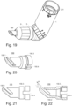
- the angle ⁇ is in the embodiment according to Figures 19 - 22 at 30°, in the embodiment according to Figures 28 to 30 at 45° and in the embodiment according to Figures 23 to 27 at 60°. This allows the powder spray direction to be changed by a further angle and the powder spray direction to be adapted even better to the workpiece geometry.
- the high-voltage line 10 comprises several sections 10.1, 10.2 and 10.3 and, similar to the gas line 20, leads through the housing 1, the swivel body 3 and the electrode holder 35.
- the section 10.1 runs through the housing 1, the section 10.2 through the swivel body 3 and the section 10.3 through the electrode holder 35.
- a contact pin is provided at the end of section 10.2 and a contact ring is provided on the electrode holder 35. This ensures that the electrical connection is always ensured, regardless of the orientation of the electrode holder 35 relative to the swivel body 3.
- the electrode holder 35 can therefore be inserted into the swivel body 3 and fixed in any rotational position using a union nut 9 on the swivel body 3.
- the rotational position is related to the longitudinal axis LA2, which in this case forms the rotational axis around which the electrode holder 35 can be rotated.
- the union nut 9 has an internal thread and the swivel body 3 has a corresponding external thread.
- the union nut 9 and the swivel body 3 can be connected to one another via these two threads.
- the electrode holder 35 can be pulled out of the swivel body 3.
- the powder spray nozzle 5 can be plugged onto the electrode holder 35 and can have a shoulder 5.3.
- the powder spray nozzle 5 can be held in position with the union nut 9, which forms a positive connection with the shoulder 5.3.
- the powder spray nozzle 5 according to Figures 1 to 10 is designed as a flat jet nozzle. It produces a flat, wide powder jet.
- the labyrinth 8 is designed as a closed, i.e. essentially dense space, It can be provided that the air channel 20, via which compressed air is fed to the high-voltage electrode 11, does not run through the labyrinth 8, but outside the labyrinth 8 (not shown in the figures).
- the part of the gas line 20.2 arranged in the swivel body 3 is - viewed in the radial direction - arranged further inwards on the inlet side than the outlet of the part of the gas line 20.1 arranged in the housing 1 (see Figure 9 ).
- the following procedure is generally used. First, the clamping nut 15 connecting the housing 1 and the swivel body 3 is loosened. Then the housing 1 and the swivel body 3 are pulled apart in the axial direction (relative to the swivel axis DA). As a rule, 1 to 10 mm is sufficient for this. Depending on the design of the interface between the housing 1 and the swivel body 3, 2 to 5 mm is sufficient. The swivel body 3 can now be swiveled relative to the housing 1 into the desired angular position. The housing 1 and the swivel body 3 are then pressed together again and the clamping nut 15 is screwed tight.
- the entire angle adapter is swiveled about the Longitudinal axis LA1 can be rotated.
- the angle adapter can then be rotated about the longitudinal axis LA1 into the desired rotational position.
- an angle scale 24 can be attached to the housing 1 of the angle adapter and a corresponding reference mark 40.2 can be attached to the gun barrel 40.
- the powder channel 2 may have a taper, which is preferably located upstream of the joint ( Fig. 3 ). On the downstream side of the joint, the powder channel 4 can widen again.
- the upstream powder channel 2.1 thus tapers in the direction of flow and the downstream powder channel 4 widens behind the joint. This allows the powder flow to be homogenized again after the joint.
- a powder mixer 17 can be provided in the powder channel 2, viewed downstream, behind the powder channel 41.
- the powder mixer 17 is provided to homogenize the powder flow. This is to center and direct the powder that flows through the angled section of the powder channel 4 (relative to the longitudinal axis LA2). After the powder-air mixture has passed the taper, it is expanded again and thus evenly distributed over the cross section of the powder channel 4.
- the powder mixer 17 has a taper 17.1 in the channel cross-section on the inlet side. This tapering section 17.1 is followed by a section with a constant cross-section 17.2 and then by a widening section 17.3.
- a powder mixer 47 can also be provided, which has one or more lamellae or blades in order to give the powder flowing through the powder channel a swirl.
- the powder mixer 47 which is also referred to as mixer for short, has four blades 47.1, 47.2, 47.3 and 47.4.
- the flow direction of the powder P is indicated by an arrow.
- the powder is swirled inside the mixer and exits the mixer outlet as a homogeneous, directed powder stream.
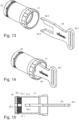
- the locking sleeve 26 is also connected to a threaded sleeve 21 via a snap connection ( Figures 13 to 15 ).
- the securing sleeve 21 has an annular snap hook on its upstream side, which - when mounted - engages in an annular groove 21.4 of the threaded sleeve 21, which is located at the downstream end of the threaded sleeve 21.
- the snap connection is designed such that the threaded sleeve 26 can rotate freely about the longitudinal axis LA1 relative to the securing sleeve 21.
- the downstream end of the threaded sleeve 21 has an internal thread 21.1 and two grooves 21.2.
- the webs 60.2 and 60.3 of an assembly tool 60 can be inserted into the grooves 21.2 if the assembly tool 60 is aligned accordingly.
- it is equipped with a handle 60.1.
- the assembly tool 60 is inserted into the threaded sleeve 21 and rotated until the webs 60.2 and 60.3 protrude into the grooves 21.2 provided for them and form a positive connection with them.
- the assembly tool 60 is then rotated together with the threaded sleeve 21 until the two webs 60.2 and 60.3 also engage in the grooves 26.2 of the locking ring 26 and also form a positive connection with it.
- the groove 26.2, the groove 21.2 and the web 60.3 of the assembly tool 60 are aligned so that the web 60.3 can be inserted into the two grooves 21.2 and 26.2.
- the assembly tool 60 can be rotated and the locking sleeve 26 can be screwed out of the housing 1 together with the threaded sleeve 21.
- the external thread 26.1 of the locking sleeve 26 is thereby unscrewed from the internal thread 1.2 in the housing 1.
- the internal thread 21.1 of the threaded sleeve 21 is intended to be screwed onto the external thread 40.1 of the pistol barrel 40. As soon as the threaded sleeve 21 is firmly screwed onto the pistol barrel 40, the angle adapter can no longer rotate about the longitudinal axis LA1.
- the sleeve 43 is inserted into the housing 1 from the upstream side.
- the locking sleeve 26 and the threaded sleeve 21 are then inserted into the housing 1 plugged in.
- the assembly tool 60 the locking sleeve 26 is now screwed to the housing 1.
- a second embodiment of the angle adapter according to the invention differs from the first embodiment essentially in the mouth area.
- a nozzle 50 is installed here, which is designed in such a way that it can accommodate a baffle plate 51. This allows a round, conical powder spray jet to be generated.
- the high-voltage line 10 leads through the nozzle 50 and the baffle plate 51, and ends as a high-voltage electrode 11 on the downstream side of the baffle plate 51.
- a third embodiment of the angle adapter is shown.
- the third embodiment differs from the other embodiments in the mouth area.
- a nozzle 150 is installed here, which is designed in such a way that it sprays the powder at an oblique angle ⁇ of around 30°.
- the nozzle slot 150.1 extends over the entire width of the powder channel 150.2.
- the nozzle 150 can be aligned on the electrode holder 35.
- the web 35.4 and the groove 150.4 form a positive connection so that the nozzle 150 cannot accidentally rotate with respect to the longitudinal axis LA2. This also applies analogously to the other nozzles.
- the angle adapter can also be equipped with a nozzle 250.
- the angle adapter is shown with the nozzle 250.
- the angle adapter can also be equipped with a nozzle 350.
- the nozzle 350 is shown.
- the nozzle slot 350.1 extends over the entire width of the powder channel 350.2.
- the angle adapter can also be equipped with a nozzle 450.
- the nozzle 450 is shown.
- the nozzle 450 is designed in such a way that it sprays the powder at an angle of around 45°.
- the nozzle slot 450.1 does not extend over the entire width of the powder channel as in the case of nozzles 5, 150, 250 and 350.
- the nozzles 5, 150, 250, 350 and 450 can be adjusted in their rotational position in relation to the longitudinal axis LA2.
- the union nut 9 is loosened so that the nozzle and the electrode holder 35 can be rotated around the longitudinal axis LA2 into the desired rotational position.
- the union nut 9 is then tightened again so that the nozzle and the electrode holder are fixed in their new rotational position. Because the nozzles can be rotated, the angle adapter is given an additional degree of freedom. This means that the powder spray direction can be changed by an additional angle.
Landscapes
- Electrostatic Spraying Apparatus (AREA)
- Nozzles (AREA)
Claims (24)
- Adaptateur angulaire pour un dispositif de pulvérisation de poudre,- avec un boîtier en amont (1), qui présente un canal de poudre en amont (2), un raccordement au dispositif de pulvérisation de poudre et un axe longitudinal (LA1) autour duquel le boîtier (1) peut tourner,- avec un corps pivotant (3) comportant un canal de poudre en aval (4) qui se raccorde au canal de poudre en amont (2),- dans lequel le corps pivotant (3) peut pivoter autour d'un axe de pivotement (DA),- avec une buse (5) qui se raccorde au corps pivotant (3),- avec une ligne à haute tension (10) qui s'étend du boîtier en amont (1) jusqu'à la buse (5) en passant par le corps pivotant (3) et qui y est conçue comme une électrode à haute tension (11),caractérisé en ce que l'axe de pivotement (DA) est oblique par rapport à l'axe longitudinal (LA1),le boîtier (1) et le corps pivotant (3) comportant plusieurs âmes (6, 18) et rainures (7, 19),les âmes faisant saillie dans les rainures et les âmes et rainures étant formées de manière à créer un labyrinthe (8) pour augmenter la distance entre la ligne à haute tension (10) et la face extérieure de l'adaptateur angulaire.
- Adaptateur angulaire selon la revendication 1,
dans lequel le canal de poudre en amont (2) se rétrécit et le canal de poudre en aval (4) s'élargit à nouveau dans le corps pivotant (3). - Adaptateur angulaire selon la revendication 1 ou 2,- avec une conduite de gaz (20), dans laquelle une partie de la conduite de gaz (20.1) passe par le boîtier en amont (1) et une autre partie de la conduite de gaz (20.2) passe par le corps pivotant (3) et- la conduite de gaz (20) est prévue pour transporter du gaz vers l'électrode haute tension (11).
- Adaptateur angulaire selon la revendication 3,
dans lequel la partie de la conduite de gaz (20.1), disposée dans le boîtier (1), est reliée côté sortie au labyrinthe (8). - Adaptateur angulaire selon la revendication 3 ou 4, dans lequel la partie de la conduite de gaz (20.2), disposée dans le corps pivotant (3), est reliée côté entrée au labyrinthe (8).
- Adaptateur angulaire selon l'une des revendications 1 à 5,
dans lequel un diélectrique est prévu dans le labyrinthe (8). - Adaptateur angulaire selon la revendication 6,
dans lequel le diélectrique est un gaz inerte ou une graisse haute tension. - Adaptateur angulaire selon l'une des revendications précédentes,
dans lequel le canal de poudre en aval (4) comporte un axe longitudinal (LA2) qui est oblique par rapport à l'axe de pivotement (DA). - Adaptateur angulaire selon l'une des revendications précédentes,- dans lequel le canal de poudre en amont (2) comporte une section de canal en amont (2.1) qui est concentrique par rapport à l'axe longitudinal (LA1), et- dans lequel le canal de poudre en amont (2) comporte une section de canal en aval (2.2) qui est concentrique par rapport à l'axe de pivotement (DA).
- Adaptateur angulaire selon l'une des revendications précédentes,
dans lequel un anneau de contact (39) est prévu au niveau de la jonction entre le boîtier en amont (1) et le corps pivotant (3), afin de relier la partie de la ligne à haute tension (10.1), se trouvant dans le boîtier en amont (1), à la partie de la ligne à haute tension (10.2) se trouvant dans le corps pivotant (3). - Adaptateur angulaire selon la revendication 10,
dans lequel l'anneau de contact (39) est disposé de manière adjacente au canal de poudre (2). - Adaptateur angulaire selon la revendication 10 ou 11,
dans lequel, vu dans le sens radial, l'anneau de contact (39) est disposé entre le canal de poudre (2) et la conduite de gaz (20). - Adaptateur angulaire selon l'une des revendications précédentes,
dans lequel un joint d'étanchéité (16), qui assure l'étanchéité du labyrinthe (8) aux gaz vers l'extérieur, est prévu dans la zone extérieure de la jonction entre le boîtier (1) et le corps pivotant (3). - Adaptateur angulaire selon l'une des revendications précédentes,
avec un écrou de serrage (15) qui est disposé au niveau de la jonction entre le boîtier (1) et le corps pivotant (3) et qui est prévu pour fixer le corps pivotant (3) au boîtier (1). - Adaptateur angulaire selon la revendication 14, dans lequel l'écrou de serrage (15) est fabriqué dans un matériau électriquement non conducteur.
- Adaptateur angulaire selon l'une des revendications précédentes,
dans lequel le labyrinthe (8) a une largeur comprise entre 0,1 mm et 0,8 mm. - Adaptateur angulaire selon l'une des revendications précédentes,
dans lequel la sortie du canal de poudre en amont (2) et l'entrée du canal de poudre en aval (4) sont conçues de manière à pouvoir être reliées l'une à l'autre de manière étanche. - Adaptateur angulaire selon l'une des revendications précédentes,
dans lequel un mélangeur de poudre (17 ; 47) est prévu dans la zone amont du canal de poudre en aval (4). - Adaptateur angulaire selon la revendication 18, dans lequel la section transversale du mélangeur de poudres (17), vue dans le sens de l'écoulement, se rétrécit d'abord et s'élargit ensuite à nouveau.
- Adaptateur angulaire selon la revendication 18, dans lequel le mélangeur de poudre (47) comporte des pales (47.1 - 47.4) pour donner un tourbillon à la poudre (P) s'écoulant par le canal de poudre (2).
- Adaptateur angulaire selon l'une des revendications 10 à 20,
dans lequel l'anneau de contact (39) est conçu comme un joint torique conducteur. - Adaptateur angulaire selon l'une des revendications 1 à 21,
avec une douille filetée (21), par laquelle le boîtier (1) peut être relié à un canon de pistolet (40), la douille filetée étant conçue de façon à permettre, à l'état desserré, une rotation de l'adaptateur angulaire par rapport au canon de pistolet (40). - Procédé de réglage de la direction de pulvérisation d'un dispositif de pulvérisation de poudre comportant un adaptateur angulaire selon l'une des revendications 1 à 22, comprenant les étapes suivantes :- un écrou de serrage (15) reliant le boîtier (1) et le corps pivotant (3) est desserré,- le corps pivotant (3) est pivoté dans la position angulaire de pivotement (8) souhaitée par rapport au boîtier (1) et,- l'écrou de serrage (15) est vissé.
- Procédé selon la revendication 23, comprenant les étapes suivantes :- la douille filetée (21) reliant le boîtier (1) au canon du pistolet (40) est desserrée,- l'adaptateur angulaire est tourné dans la position souhaitée par rapport au canon du pistolet (40) et- la douille filetée (21) est vissée.
Priority Applications (4)
| Application Number | Priority Date | Filing Date | Title |
|---|---|---|---|
| PL22169629.7T PL4268971T3 (pl) | 2022-04-25 | 2022-04-25 | Adapter kątowy do urządzenia do malowania proszkowego |
| EP22169629.7A EP4268971B1 (fr) | 2022-04-25 | 2022-04-25 | Adaptateur angulaire pour un dispositif de pulvérisation de poudre |
| US18/304,984 US12533689B2 (en) | 2022-04-25 | 2023-04-21 | Angle adapter for a powder spray device |
| CN202310433262.6A CN116943905A (zh) | 2022-04-25 | 2023-04-21 | 用于粉末喷涂装置的角度适配器 |
Applications Claiming Priority (1)
| Application Number | Priority Date | Filing Date | Title |
|---|---|---|---|
| EP22169629.7A EP4268971B1 (fr) | 2022-04-25 | 2022-04-25 | Adaptateur angulaire pour un dispositif de pulvérisation de poudre |
Publications (2)
| Publication Number | Publication Date |
|---|---|
| EP4268971A1 EP4268971A1 (fr) | 2023-11-01 |
| EP4268971B1 true EP4268971B1 (fr) | 2025-03-05 |
Family
ID=81386725
Family Applications (1)
| Application Number | Title | Priority Date | Filing Date |
|---|---|---|---|
| EP22169629.7A Active EP4268971B1 (fr) | 2022-04-25 | 2022-04-25 | Adaptateur angulaire pour un dispositif de pulvérisation de poudre |
Country Status (4)
| Country | Link |
|---|---|
| US (1) | US12533689B2 (fr) |
| EP (1) | EP4268971B1 (fr) |
| CN (1) | CN116943905A (fr) |
| PL (1) | PL4268971T3 (fr) |
Families Citing this family (1)
| Publication number | Priority date | Publication date | Assignee | Title |
|---|---|---|---|---|
| DE102024117830A1 (de) * | 2024-06-25 | 2026-01-08 | Dürr Systems Ag | Betriebsverfahren und Applikationsvorrichtung zur Überprüfung, ob eine Anbaukomponente korrekt, inkorrekt oder nicht montiert ist |
Family Cites Families (8)
| Publication number | Priority date | Publication date | Assignee | Title |
|---|---|---|---|---|
| SE513348C2 (sv) * | 1993-07-02 | 2000-08-28 | Abb Ab | Industrirobot |
| US5765761A (en) * | 1995-07-26 | 1998-06-16 | Universtiy Of Georgia Research Foundation, Inc. | Electrostatic-induction spray-charging nozzle system |
| EP0837735B1 (fr) * | 1995-07-26 | 2004-02-25 | University Of Georgia Research Foundation, Inc. | Buses electrostatiques pour liquides abrasifs et conducteurs |
| US6817553B2 (en) * | 2003-02-04 | 2004-11-16 | Efc Systems, Inc. | Powder paint spray coating apparatus having selectable, modular spray applicators |
| DE102009013979A1 (de) * | 2009-03-19 | 2010-09-23 | Dürr Systems GmbH | Elektrodenanordnung für einen elektrostatischen Zerstäuber |
| US8162238B2 (en) * | 2009-11-03 | 2012-04-24 | Living Fountain Plastic Industrial Co., Ltd. | Spray type liquid pressure head |
| DE202012004571U1 (de) * | 2012-05-10 | 2012-09-03 | Reinhold Gregarek | Rohrhülse zur tribostatischen Aufladung eines Lackpulvers und mit der Rohrhülse mindestens dreifach pulverbeschichtetes Bauteil |
| DE102018133713A1 (de) * | 2018-12-31 | 2020-07-02 | Gema Switzerland Gmbh | Pulverdünnstrompumpe sowie Verfahren zum Betreiben einer Pulverdünnstrompumpe |
-
2022
- 2022-04-25 PL PL22169629.7T patent/PL4268971T3/pl unknown
- 2022-04-25 EP EP22169629.7A patent/EP4268971B1/fr active Active
-
2023
- 2023-04-21 CN CN202310433262.6A patent/CN116943905A/zh active Pending
- 2023-04-21 US US18/304,984 patent/US12533689B2/en active Active
Also Published As
| Publication number | Publication date |
|---|---|
| US12533689B2 (en) | 2026-01-27 |
| US20230338973A1 (en) | 2023-10-26 |
| EP4268971A1 (fr) | 2023-11-01 |
| CN116943905A (zh) | 2023-10-27 |
| PL4268971T3 (pl) | 2025-07-07 |
Similar Documents
| Publication | Publication Date | Title |
|---|---|---|
| EP0212122B1 (fr) | Appareil de pulvérisation pour l'application électrostatique de poudre | |
| EP0236795B1 (fr) | Appareil de pulvérisation électrostatique pour poudre de revêtement | |
| DE19528398A1 (de) | Elektrostatische Sprühvorrichtung für Beschichtungsmaterial | |
| DE2731601A1 (de) | Elektrostatische spruehbeschichtungspistole | |
| DE3100001C2 (fr) | ||
| DE4411438A1 (de) | Schwenkbare Sprühdüsenanordnung | |
| DE19546970A1 (de) | Sprühbeschichtungsvorrichtung zur elektrostatischen Sprühbeschichtung | |
| DE3514523C2 (fr) | ||
| DE102009013379A1 (de) | Vorrichtung zum Beschichten eines Substrats | |
| EP4268971B1 (fr) | Adaptateur angulaire pour un dispositif de pulvérisation de poudre | |
| DE1965509C3 (de) | Elektrostatische Spritzpistole | |
| DE2914960B1 (de) | Verfahren und Vorrichtung zum Spruehbeschichten des Inneren von eine Naht aufweisenden rohrfoermigen Koerpern | |
| DE10111697A1 (de) | Pulversprühpistole für Beschichtungspulver | |
| DE2903148A1 (de) | Vorrichtung fuer die beschichtung von gegenstaenden mit elektrostatisch aufgeladenem staub | |
| DE10053295C2 (de) | Hochrotationszerstäuber zur Aufbringung von Pulverlack | |
| EP1752224B1 (fr) | Porte-electrode pour une appareil de pulverisation | |
| EP0681872A2 (fr) | Dispositif de fixation d'un dispositif de pulvérisation | |
| DE19507365C2 (de) | Vorrichtung zum Versprühen eines Zweistoffgemisches | |
| WO2019053055A1 (fr) | Chalumeau tig de soudage, brasage ou revêtement | |
| EP0637466B1 (fr) | Dispositif de projection électrostatique de produit en poudre | |
| DE4312994C2 (de) | Vorrichtung zur Verspritzung von Suspensionen, insbesondere Mörteln | |
| DE10147858A1 (de) | Spritzbeschichtungsvorrichtung | |
| EP4243992B1 (fr) | Dispositif d'éclairage pour pistolet de pulvérisation et pistolet de pulvérisation avec un tel dispositif d'éclairage | |
| EP2650051B1 (fr) | Insert à clavette pour rallonge de tuyau de poudre d'un pistolet de pulvérisation de poudre fonctionnant sous haute tension et rallonge de tuyau de poudre avec insert à clavette | |
| DE3329880A1 (de) | Verfahren zum spritzbeschichten ohne luft und spritzpistole fuer das beschichten ohne luft |
Legal Events
| Date | Code | Title | Description |
|---|---|---|---|
| PUAI | Public reference made under article 153(3) epc to a published international application that has entered the european phase |
Free format text: ORIGINAL CODE: 0009012 |
|
| STAA | Information on the status of an ep patent application or granted ep patent |
Free format text: STATUS: THE APPLICATION HAS BEEN PUBLISHED |
|
| AK | Designated contracting states |
Kind code of ref document: A1 Designated state(s): AL AT BE BG CH CY CZ DE DK EE ES FI FR GB GR HR HU IE IS IT LI LT LU LV MC MK MT NL NO PL PT RO RS SE SI SK SM TR |
|
| STAA | Information on the status of an ep patent application or granted ep patent |
Free format text: STATUS: REQUEST FOR EXAMINATION WAS MADE |
|
| 17P | Request for examination filed |
Effective date: 20240502 |
|
| RBV | Designated contracting states (corrected) |
Designated state(s): AL AT BE BG CH CY CZ DE DK EE ES FI FR GB GR HR HU IE IS IT LI LT LU LV MC MK MT NL NO PL PT RO RS SE SI SK SM TR |
|
| GRAP | Despatch of communication of intention to grant a patent |
Free format text: ORIGINAL CODE: EPIDOSNIGR1 |
|
| STAA | Information on the status of an ep patent application or granted ep patent |
Free format text: STATUS: GRANT OF PATENT IS INTENDED |
|
| INTG | Intention to grant announced |
Effective date: 20241017 |
|
| GRAS | Grant fee paid |
Free format text: ORIGINAL CODE: EPIDOSNIGR3 |
|
| GRAA | (expected) grant |
Free format text: ORIGINAL CODE: 0009210 |
|
| STAA | Information on the status of an ep patent application or granted ep patent |
Free format text: STATUS: THE PATENT HAS BEEN GRANTED |
|
| AK | Designated contracting states |
Kind code of ref document: B1 Designated state(s): AL AT BE BG CH CY CZ DE DK EE ES FI FR GB GR HR HU IE IS IT LI LT LU LV MC MK MT NL NO PL PT RO RS SE SI SK SM TR |
|
| REG | Reference to a national code |
Ref country code: GB Ref legal event code: FG4D Free format text: NOT ENGLISH |
|
| REG | Reference to a national code |
Ref country code: CH Ref legal event code: EP |
|
| REG | Reference to a national code |
Ref country code: DE Ref legal event code: R096 Ref document number: 502022003069 Country of ref document: DE |
|
| REG | Reference to a national code |
Ref country code: IE Ref legal event code: FG4D Free format text: LANGUAGE OF EP DOCUMENT: GERMAN |
|
| PG25 | Lapsed in a contracting state [announced via postgrant information from national office to epo] |
Ref country code: RS Free format text: LAPSE BECAUSE OF FAILURE TO SUBMIT A TRANSLATION OF THE DESCRIPTION OR TO PAY THE FEE WITHIN THE PRESCRIBED TIME-LIMIT Effective date: 20250605 |
|
| PG25 | Lapsed in a contracting state [announced via postgrant information from national office to epo] |
Ref country code: FI Free format text: LAPSE BECAUSE OF FAILURE TO SUBMIT A TRANSLATION OF THE DESCRIPTION OR TO PAY THE FEE WITHIN THE PRESCRIBED TIME-LIMIT Effective date: 20250305 |
|
| PGFP | Annual fee paid to national office [announced via postgrant information from national office to epo] |
Ref country code: DE Payment date: 20250430 Year of fee payment: 4 |
|
| REG | Reference to a national code |
Ref country code: NL Ref legal event code: MP Effective date: 20250305 |
|
| PG25 | Lapsed in a contracting state [announced via postgrant information from national office to epo] |
Ref country code: ES Free format text: LAPSE BECAUSE OF FAILURE TO SUBMIT A TRANSLATION OF THE DESCRIPTION OR TO PAY THE FEE WITHIN THE PRESCRIBED TIME-LIMIT Effective date: 20250305 |
|
| REG | Reference to a national code |
Ref country code: LT Ref legal event code: MG9D |
|
| PG25 | Lapsed in a contracting state [announced via postgrant information from national office to epo] |
Ref country code: NO Free format text: LAPSE BECAUSE OF FAILURE TO SUBMIT A TRANSLATION OF THE DESCRIPTION OR TO PAY THE FEE WITHIN THE PRESCRIBED TIME-LIMIT Effective date: 20250605 |
|
| PG25 | Lapsed in a contracting state [announced via postgrant information from national office to epo] |
Ref country code: HR Free format text: LAPSE BECAUSE OF FAILURE TO SUBMIT A TRANSLATION OF THE DESCRIPTION OR TO PAY THE FEE WITHIN THE PRESCRIBED TIME-LIMIT Effective date: 20250305 |
|
| PG25 | Lapsed in a contracting state [announced via postgrant information from national office to epo] |
Ref country code: LV Free format text: LAPSE BECAUSE OF FAILURE TO SUBMIT A TRANSLATION OF THE DESCRIPTION OR TO PAY THE FEE WITHIN THE PRESCRIBED TIME-LIMIT Effective date: 20250305 |
|
| PG25 | Lapsed in a contracting state [announced via postgrant information from national office to epo] |
Ref country code: GR Free format text: LAPSE BECAUSE OF FAILURE TO SUBMIT A TRANSLATION OF THE DESCRIPTION OR TO PAY THE FEE WITHIN THE PRESCRIBED TIME-LIMIT Effective date: 20250606 Ref country code: BG Free format text: LAPSE BECAUSE OF FAILURE TO SUBMIT A TRANSLATION OF THE DESCRIPTION OR TO PAY THE FEE WITHIN THE PRESCRIBED TIME-LIMIT Effective date: 20250305 |
|
| PGFP | Annual fee paid to national office [announced via postgrant information from national office to epo] |
Ref country code: CH Payment date: 20250501 Year of fee payment: 4 |
|
| PGFP | Annual fee paid to national office [announced via postgrant information from national office to epo] |
Ref country code: AT Payment date: 20250721 Year of fee payment: 4 |
|
| PG25 | Lapsed in a contracting state [announced via postgrant information from national office to epo] |
Ref country code: NL Free format text: LAPSE BECAUSE OF FAILURE TO SUBMIT A TRANSLATION OF THE DESCRIPTION OR TO PAY THE FEE WITHIN THE PRESCRIBED TIME-LIMIT Effective date: 20250305 |
|
| PG25 | Lapsed in a contracting state [announced via postgrant information from national office to epo] |
Ref country code: SE Free format text: LAPSE BECAUSE OF FAILURE TO SUBMIT A TRANSLATION OF THE DESCRIPTION OR TO PAY THE FEE WITHIN THE PRESCRIBED TIME-LIMIT Effective date: 20250305 |
|
| PG25 | Lapsed in a contracting state [announced via postgrant information from national office to epo] |
Ref country code: SM Free format text: LAPSE BECAUSE OF FAILURE TO SUBMIT A TRANSLATION OF THE DESCRIPTION OR TO PAY THE FEE WITHIN THE PRESCRIBED TIME-LIMIT Effective date: 20250305 |
|
| PG25 | Lapsed in a contracting state [announced via postgrant information from national office to epo] |
Ref country code: PT Free format text: LAPSE BECAUSE OF FAILURE TO SUBMIT A TRANSLATION OF THE DESCRIPTION OR TO PAY THE FEE WITHIN THE PRESCRIBED TIME-LIMIT Effective date: 20250707 |
|
| PG25 | Lapsed in a contracting state [announced via postgrant information from national office to epo] |
Ref country code: IT Free format text: LAPSE BECAUSE OF FAILURE TO SUBMIT A TRANSLATION OF THE DESCRIPTION OR TO PAY THE FEE WITHIN THE PRESCRIBED TIME-LIMIT Effective date: 20250305 |
|
| PG25 | Lapsed in a contracting state [announced via postgrant information from national office to epo] |
Ref country code: EE Free format text: LAPSE BECAUSE OF FAILURE TO SUBMIT A TRANSLATION OF THE DESCRIPTION OR TO PAY THE FEE WITHIN THE PRESCRIBED TIME-LIMIT Effective date: 20250305 Ref country code: CZ Free format text: LAPSE BECAUSE OF FAILURE TO SUBMIT A TRANSLATION OF THE DESCRIPTION OR TO PAY THE FEE WITHIN THE PRESCRIBED TIME-LIMIT Effective date: 20250305 |
|
| PG25 | Lapsed in a contracting state [announced via postgrant information from national office to epo] |
Ref country code: RO Free format text: LAPSE BECAUSE OF FAILURE TO SUBMIT A TRANSLATION OF THE DESCRIPTION OR TO PAY THE FEE WITHIN THE PRESCRIBED TIME-LIMIT Effective date: 20250305 |
|
| REG | Reference to a national code |
Ref country code: DE Ref legal event code: R081 Ref document number: 502022003069 Country of ref document: DE Owner name: J. WAGNER GMBH, DE Free format text: FORMER OWNER: WAGNER INTERNATIONAL AG, ALTSTAETTEN, CH |
|
| PG25 | Lapsed in a contracting state [announced via postgrant information from national office to epo] |
Ref country code: SK Free format text: LAPSE BECAUSE OF FAILURE TO SUBMIT A TRANSLATION OF THE DESCRIPTION OR TO PAY THE FEE WITHIN THE PRESCRIBED TIME-LIMIT Effective date: 20250305 |
|
| PG25 | Lapsed in a contracting state [announced via postgrant information from national office to epo] |
Ref country code: IS Free format text: LAPSE BECAUSE OF FAILURE TO SUBMIT A TRANSLATION OF THE DESCRIPTION OR TO PAY THE FEE WITHIN THE PRESCRIBED TIME-LIMIT Effective date: 20250705 |
|
| RAP2 | Party data changed (patent owner data changed or rights of a patent transferred) |
Owner name: J. WAGNER GMBH |
|
| REG | Reference to a national code |
Ref country code: DE Ref legal event code: R097 Ref document number: 502022003069 Country of ref document: DE |
|
| PG25 | Lapsed in a contracting state [announced via postgrant information from national office to epo] |
Ref country code: LU Free format text: LAPSE BECAUSE OF NON-PAYMENT OF DUE FEES Effective date: 20250425 |
|
| PG25 | Lapsed in a contracting state [announced via postgrant information from national office to epo] |
Ref country code: MC Free format text: LAPSE BECAUSE OF FAILURE TO SUBMIT A TRANSLATION OF THE DESCRIPTION OR TO PAY THE FEE WITHIN THE PRESCRIBED TIME-LIMIT Effective date: 20250305 |
|
| REG | Reference to a national code |
Ref country code: BE Ref legal event code: MM Effective date: 20250430 |
|
| PLBE | No opposition filed within time limit |
Free format text: ORIGINAL CODE: 0009261 |
|
| STAA | Information on the status of an ep patent application or granted ep patent |
Free format text: STATUS: NO OPPOSITION FILED WITHIN TIME LIMIT |
|
| PG25 | Lapsed in a contracting state [announced via postgrant information from national office to epo] |
Ref country code: DK Free format text: LAPSE BECAUSE OF FAILURE TO SUBMIT A TRANSLATION OF THE DESCRIPTION OR TO PAY THE FEE WITHIN THE PRESCRIBED TIME-LIMIT Effective date: 20250305 |
|
| REG | Reference to a national code |
Ref country code: CH Ref legal event code: L10 Free format text: ST27 STATUS EVENT CODE: U-0-0-L10-L00 (AS PROVIDED BY THE NATIONAL OFFICE) Effective date: 20260114 |
|
| PG25 | Lapsed in a contracting state [announced via postgrant information from national office to epo] |
Ref country code: BE Free format text: LAPSE BECAUSE OF NON-PAYMENT OF DUE FEES Effective date: 20250430 |
|
| 26N | No opposition filed |
Effective date: 20251208 |
|
| PG25 | Lapsed in a contracting state [announced via postgrant information from national office to epo] |
Ref country code: IE Free format text: LAPSE BECAUSE OF NON-PAYMENT OF DUE FEES Effective date: 20250425 |
|
| PG25 | Lapsed in a contracting state [announced via postgrant information from national office to epo] |
Ref country code: FR Free format text: LAPSE BECAUSE OF NON-PAYMENT OF DUE FEES Effective date: 20250505 |
|
| PGFP | Annual fee paid to national office [announced via postgrant information from national office to epo] |
Ref country code: PL Payment date: 20260317 Year of fee payment: 5 |