EP4269020A1 - Procédé de soudage à l'arc sous protection gazeuse, joint soudé et procédé de production de joint soudé - Google Patents
Procédé de soudage à l'arc sous protection gazeuse, joint soudé et procédé de production de joint soudé Download PDFInfo
- Publication number
- EP4269020A1 EP4269020A1 EP22771289.0A EP22771289A EP4269020A1 EP 4269020 A1 EP4269020 A1 EP 4269020A1 EP 22771289 A EP22771289 A EP 22771289A EP 4269020 A1 EP4269020 A1 EP 4269020A1
- Authority
- EP
- European Patent Office
- Prior art keywords
- welding
- groove
- gas
- shielded arc
- root
- Prior art date
- Legal status (The legal status is an assumption and is not a legal conclusion. Google has not performed a legal analysis and makes no representation as to the accuracy of the status listed.)
- Pending
Links
Images

Classifications
-
- B—PERFORMING OPERATIONS; TRANSPORTING
- B23—MACHINE TOOLS; METAL-WORKING NOT OTHERWISE PROVIDED FOR
- B23K—SOLDERING OR UNSOLDERING; WELDING; CLADDING OR PLATING BY SOLDERING OR WELDING; CUTTING BY APPLYING HEAT LOCALLY, e.g. FLAME CUTTING; WORKING BY LASER BEAM
- B23K9/00—Arc welding or cutting
- B23K9/16—Arc welding or cutting making use of shielding gas
-
- B—PERFORMING OPERATIONS; TRANSPORTING
- B23—MACHINE TOOLS; METAL-WORKING NOT OTHERWISE PROVIDED FOR
- B23K—SOLDERING OR UNSOLDERING; WELDING; CLADDING OR PLATING BY SOLDERING OR WELDING; CUTTING BY APPLYING HEAT LOCALLY, e.g. FLAME CUTTING; WORKING BY LASER BEAM
- B23K35/00—Rods, electrodes, materials, or media, for use in soldering, welding, or cutting
- B23K35/22—Rods, electrodes, materials, or media, for use in soldering, welding, or cutting characterised by the composition or nature of the material
- B23K35/24—Selection of soldering or welding materials proper
- B23K35/30—Selection of soldering or welding materials proper with the principal constituent melting at less than 1550°C
- B23K35/3053—Fe as the principal constituent
- B23K35/3073—Fe as the principal constituent with Mn as next major constituent
-
- B—PERFORMING OPERATIONS; TRANSPORTING
- B23—MACHINE TOOLS; METAL-WORKING NOT OTHERWISE PROVIDED FOR
- B23K—SOLDERING OR UNSOLDERING; WELDING; CLADDING OR PLATING BY SOLDERING OR WELDING; CUTTING BY APPLYING HEAT LOCALLY, e.g. FLAME CUTTING; WORKING BY LASER BEAM
- B23K37/00—Auxiliary devices or processes, not specially adapted for a procedure covered by only one of the other main groups of this subclass
- B23K37/06—Auxiliary devices or processes, not specially adapted for a procedure covered by only one of the other main groups of this subclass for positioning the molten material, e.g. confining it to a desired area
-
- B—PERFORMING OPERATIONS; TRANSPORTING
- B23—MACHINE TOOLS; METAL-WORKING NOT OTHERWISE PROVIDED FOR
- B23K—SOLDERING OR UNSOLDERING; WELDING; CLADDING OR PLATING BY SOLDERING OR WELDING; CUTTING BY APPLYING HEAT LOCALLY, e.g. FLAME CUTTING; WORKING BY LASER BEAM
- B23K9/00—Arc welding or cutting
- B23K9/02—Seam welding; Backing means; Inserts
-
- B—PERFORMING OPERATIONS; TRANSPORTING
- B23—MACHINE TOOLS; METAL-WORKING NOT OTHERWISE PROVIDED FOR
- B23K—SOLDERING OR UNSOLDERING; WELDING; CLADDING OR PLATING BY SOLDERING OR WELDING; CUTTING BY APPLYING HEAT LOCALLY, e.g. FLAME CUTTING; WORKING BY LASER BEAM
- B23K9/00—Arc welding or cutting
- B23K9/02—Seam welding; Backing means; Inserts
- B23K9/025—Seam welding; Backing means; Inserts for rectilinear seams
-
- B—PERFORMING OPERATIONS; TRANSPORTING
- B23—MACHINE TOOLS; METAL-WORKING NOT OTHERWISE PROVIDED FOR
- B23K—SOLDERING OR UNSOLDERING; WELDING; CLADDING OR PLATING BY SOLDERING OR WELDING; CUTTING BY APPLYING HEAT LOCALLY, e.g. FLAME CUTTING; WORKING BY LASER BEAM
- B23K9/00—Arc welding or cutting
- B23K9/02—Seam welding; Backing means; Inserts
- B23K9/035—Seam welding; Backing means; Inserts with backing means disposed under the seam
-
- B—PERFORMING OPERATIONS; TRANSPORTING
- B23—MACHINE TOOLS; METAL-WORKING NOT OTHERWISE PROVIDED FOR
- B23K—SOLDERING OR UNSOLDERING; WELDING; CLADDING OR PLATING BY SOLDERING OR WELDING; CUTTING BY APPLYING HEAT LOCALLY, e.g. FLAME CUTTING; WORKING BY LASER BEAM
- B23K9/00—Arc welding or cutting
- B23K9/09—Arrangements or circuits for arc welding with pulsed current or voltage
-
- B—PERFORMING OPERATIONS; TRANSPORTING
- B23—MACHINE TOOLS; METAL-WORKING NOT OTHERWISE PROVIDED FOR
- B23K—SOLDERING OR UNSOLDERING; WELDING; CLADDING OR PLATING BY SOLDERING OR WELDING; CUTTING BY APPLYING HEAT LOCALLY, e.g. FLAME CUTTING; WORKING BY LASER BEAM
- B23K9/00—Arc welding or cutting
- B23K9/16—Arc welding or cutting making use of shielding gas
- B23K9/173—Arc welding or cutting making use of shielding gas and of a consumable electrode
-
- B—PERFORMING OPERATIONS; TRANSPORTING
- B23—MACHINE TOOLS; METAL-WORKING NOT OTHERWISE PROVIDED FOR
- B23K—SOLDERING OR UNSOLDERING; WELDING; CLADDING OR PLATING BY SOLDERING OR WELDING; CUTTING BY APPLYING HEAT LOCALLY, e.g. FLAME CUTTING; WORKING BY LASER BEAM
- B23K9/00—Arc welding or cutting
- B23K9/23—Arc welding or cutting taking account of the properties of the materials to be welded
-
- B—PERFORMING OPERATIONS; TRANSPORTING
- B23—MACHINE TOOLS; METAL-WORKING NOT OTHERWISE PROVIDED FOR
- B23K—SOLDERING OR UNSOLDERING; WELDING; CLADDING OR PLATING BY SOLDERING OR WELDING; CUTTING BY APPLYING HEAT LOCALLY, e.g. FLAME CUTTING; WORKING BY LASER BEAM
- B23K9/00—Arc welding or cutting
- B23K9/24—Features related to electrodes
- B23K9/28—Supporting devices for electrodes
- B23K9/29—Supporting devices adapted for making use of shielding means
- B23K9/291—Supporting devices adapted for making use of shielding means the shielding means being a gas
- B23K9/295—Supporting devices adapted for making use of shielding means the shielding means being a gas using consumable wire electrodes
-
- C—CHEMISTRY; METALLURGY
- C22—METALLURGY; FERROUS OR NON-FERROUS ALLOYS; TREATMENT OF ALLOYS OR NON-FERROUS METALS
- C22C—ALLOYS
- C22C38/00—Ferrous alloys, e.g. steel alloys
- C22C38/005—Ferrous alloys, e.g. steel alloys containing rare earths, i.e. Sc, Y, Lanthanides
-
- C—CHEMISTRY; METALLURGY
- C22—METALLURGY; FERROUS OR NON-FERROUS ALLOYS; TREATMENT OF ALLOYS OR NON-FERROUS METALS
- C22C—ALLOYS
- C22C38/00—Ferrous alloys, e.g. steel alloys
- C22C38/02—Ferrous alloys, e.g. steel alloys containing silicon
-
- C—CHEMISTRY; METALLURGY
- C22—METALLURGY; FERROUS OR NON-FERROUS ALLOYS; TREATMENT OF ALLOYS OR NON-FERROUS METALS
- C22C—ALLOYS
- C22C38/00—Ferrous alloys, e.g. steel alloys
- C22C38/04—Ferrous alloys, e.g. steel alloys containing manganese
-
- B—PERFORMING OPERATIONS; TRANSPORTING
- B23—MACHINE TOOLS; METAL-WORKING NOT OTHERWISE PROVIDED FOR
- B23K—SOLDERING OR UNSOLDERING; WELDING; CLADDING OR PLATING BY SOLDERING OR WELDING; CUTTING BY APPLYING HEAT LOCALLY, e.g. FLAME CUTTING; WORKING BY LASER BEAM
- B23K2103/00—Materials to be soldered, welded or cut
- B23K2103/02—Iron or ferrous alloys
- B23K2103/04—Steel or steel alloys
-
- B—PERFORMING OPERATIONS; TRANSPORTING
- B23—MACHINE TOOLS; METAL-WORKING NOT OTHERWISE PROVIDED FOR
- B23K—SOLDERING OR UNSOLDERING; WELDING; CLADDING OR PLATING BY SOLDERING OR WELDING; CUTTING BY APPLYING HEAT LOCALLY, e.g. FLAME CUTTING; WORKING BY LASER BEAM
- B23K35/00—Rods, electrodes, materials, or media, for use in soldering, welding, or cutting
- B23K35/22—Rods, electrodes, materials, or media, for use in soldering, welding, or cutting characterised by the composition or nature of the material
- B23K35/38—Selection of media, e.g. special atmospheres for surrounding the working area
- B23K35/383—Selection of media, e.g. special atmospheres for surrounding the working area mainly containing noble gases or nitrogen
Definitions
- the present invention relates to a gas-shielded arc welding method, a welded joint obtained using the gas-shielded arc welding method, and a method for producing the welded joint.
- the present invention relates to a root pass method in gas-shielded arc welding of steel plates.
- multi-layer multipass welding is effective in reducing the welding heat input.
- the efficiency of the procedure decreases. Therefore, to reduce the number of welding passes in one-side butt welding while the welding heat input is reduced, it is important to reduce the groove angle or the root gap to thereby reduce the groove area.
- the groove angle or the root gap is reduced, a problem arises in that welding defects such as incomplete fusion of the walls of the groove can easily occur.
- Patent Literature 1 discloses a technique for preventing incomplete fusion by using a welding machine including a rotatable wire feeding tube and a mechanism for allowing a welding wire to be inclined with respect to a welding torch.
- Patent Literature 2 discloses a technique for preventing incomplete fusion by using a combination of magnetic oscillation and current waveform control. These welding methods are effective in preventing incomplete fusion in narrow-gap welding, but a specially designed device need to be introduced.
- Patent Literature 3 discloses a technique for preventing incomplete fusion by dividing a weld seam into a plurality of sections and oscillating an electrode in the direction of the weld seam.
- this welding method the welding cannot be performed continuously over the entire weld seam, and therefore the efficiency of the operation is problematic.
- the present inventors have produced welded joints by subjecting steel plates to one-side butt-welding using gas-shielded arc welding under various test conditions and evaluated the quality of the welds and the characteristics of the welds. Then the inventors have found that, by applying a ceramic-made backing material to the bottom surface of the groove and selecting appropriate root pass conditions according to the shape of the groove, good weld quality and good weld characteristic are obtained.
- the present invention is a gas-shielded arc welding method for performing one-side butt welding of steel plates.
- this welding method two steel plates having a prescribed thickness are butted against each other, and the butted steel plates are joined together by gas-shielded arc welding (which may be hereinafter referred to simply as "welding").
- welding gas-shielded arc welding
- the welding conditions when root pass in this welding method is performed are defined.
- a ceramic-made backing material is attached to the bottom surface of a groove between the steel plates, and the root pass is performed in one pass using a welding current I (A) of 200 to 450 A and a welding voltage V (V) of 25 to 50 V such that welding heat input Q (kJ/mm) is controlled within the range defined by formula 1 described later (such that the welding heat input Q (kJ/mm) satisfies formula 1).
- the steel plates used in the invention are steel plates used for steel structures such as buildings and ships.
- Examples of the strength of the steel plates include 490 MPa-grade steel plates, 550 MPa-grade steel plates, 590 MPa-grade steel plates, and 780 MPa-grade steel plates.
- the thickness t (mm) of the steel plates is preferably in the range of 20 to 100 mm.
- Fig. 1 is a cross-sectional view of two butted steel plates in their thickness direction and illustrates the shape of the groove between the steel plates. As shown in Fig. 1 , the angle between the groove face of the butted steel plates 1 is defined as an groove angle (groove angle) ⁇ (°)
- the groove angle ⁇ of the butt groove is preferably a narrow groove of 35° or less. If the groove angle ⁇ exceeds 35°, the cross-sectional area of the groove is large. Therefore, the number of welding passes in the subsequent passes increases, and high procedure efficiency is not obtained. If the groove angle ⁇ is less than 0° (i.e., if the upper portion of the groove is narrower than its bottom portion), incomplete fusion occurs at the bottom portion of the groove. Therefore, the lower limit of the groove angle ⁇ is 0°.
- the groove angle ⁇ is more preferably from 0° to 20° inclusive.
- the groove angle ⁇ is preferably from 0° to 10° inclusive.
- the root gap which is the narrowest lower gap of the groove portion between the butted steel plates 1, is represented by G (mm).
- G the root gap
- the groove angle ⁇ is set to from 0° to 20° inclusive
- G is more preferably 8 mm or more and is more preferably 14 mm or less.
- the ceramic-made backing material that can be detached after the welding is used as a backing material for preventing burn-through.
- the ceramic-made backing material used may have, for example, a chemical composition containing, in % by mass, SiO 2 : 30 to 70%, Al 2 O 3 : 10 to 50%, and MgO: 3 to 20%.
- a ceramic-made backing material with glass fibers deposited thereon may also be used.
- the ceramic-made backing material is used is as follows. When a gap is present between the base material and the backing material, the gap serves as a stress concentration zone that may become the origin of fatigue cracking or brittle fracture. However, by using the ceramic-made backing material to allow a penetration bead to be formed, the gap between the base material and the backing material can be eliminated.
- the welding current I (A) in the root pass is lower than 200 A, the arc pressure is low, and the bottom portion of the groove is not easily melted. If the welding current I (A) in the root pass is higher than 450 A, the feedability of the welding wire becomes unstable, so that the welding becomes unstable. Therefore, the welding current I (A) in the root pass is 200 to 450 A.
- the welding current I (A) is preferably 200 to 350 A.
- the welding voltage V (V) in the root pass is lower than 25 V, the arc cannot be stably maintained. In this case, the welding may be unstable, and the weld bead tends to have a convex shape. If the welding voltage V (V) in the root pass is higher than 50 V, the arc pressure is low, and the bottom portion of the groove is not easily melted. Therefore, the welding voltage V (V) in the root pass is 25 to 50 V.
- the welding voltage V (V) is preferably 28 to 40 V and more preferably 30 to 40 V.
- the range of the welding speed S in the root pass is preferably 50 to 300 mm/min. If the welding speed S is excessively low, the amount of penetration in the bottom portion of the groove decreases. If the welding speed S is excessively high, an undercut tends to occur.
- the welding speed S is more preferably from 100 mm/min to 250 mm/min inclusive. The welding speed S can be appropriately selected within the above range according to the balance between the welding current I and the welding voltage V.
- the welding heat input Q in the root pass is set such that the relation between the root gap G (mm) and the welding heat input Q (kJ/mm) satisfies the following formula 1. 0.4 ⁇ G ⁇ 1 ⁇ Q ⁇ 0.6 ⁇ G + 1
- G the root gap (mm).
- the value of the welding heat input Q (kJ/mm) in formula 1 can be determined using the formula [I ⁇ V ⁇ 60 / S / 1000].
- I is the welding current (A);
- V is the welding voltage (V); and
- S is the welding speed (mm /min).
- the welding heat input Q (kJ/mm) in the present invention satisfies formula 1 above and is 1 to 12 kJ/mm.
- Q in formula 1 above is preferably (0.4 ⁇ G - 0.5) or more and is preferably (0.6 ⁇ G + 0.5) or less.
- the polarity of the welding may be selected from any of straight polarity (in which the steel material is connected with the positive terminal and the welding wire is connected with the negative terminal) and reverse polarity (in which the steel material is connected with the negative terminal and the welding wire is connected with the positive terminal).
- straight polarity in which the steel material is connected with the positive terminal and the welding wire is connected with the negative terminal
- reverse polarity in which the steel material is connected with the negative terminal and the welding wire is connected with the positive terminal.
- the polarity of the welding is set to the straight polarity and that an REM-added wire (welding wire) described later is used for the welding. This is because the arc is easily concentrated on the bottom portion of the groove, so that the bottom portion of the groove can be stably melted.
- the welding wire contains, on a mass basis (in % by mass), C: 0.05 to 0.15%, Si: 0.10 to 1.00%, Mn: 0.80 to 2.60%, P: 0.030% or less, and S: 0.030% or less, with the balance being Fe and incidental impurities. Note that “% by mass” is denoted simply by “%,” unless otherwise specified.
- C is an element that is important for the weld metal to have sufficient strength and has the effect of reducing the viscosity of the molten steel to thereby improve its fluidity. If the content of C is less than 0.05%, this effect is not obtained. If the content of C exceeds 0.15%, the behavior of molten droplets and the molten pool becomes unstable, and also the toughness of the weld metal decreases. Therefore, the content of C is preferably 0.05 to 0.15%. The content of C is more preferably 0.05 to 0.10%.
- Si is an element that has a deoxidization effect and is essential for deoxidization of the weld metal. Si further has the effect of preventing the spread of the arc in the straight polarity welding to thereby increase the number of times of molten droplet transfer. If the content of Si is less than 0.10%, these effects are not obtained. If the content of Si exceeds 1.00%, the arc becomes unstable, and the number of spatters increases. Therefore, the content of Si is preferably 0.10 to 1.00%. The content of Si is more preferably 0.30 to 1.00%.
- Mn is an element that has the deoxidization effect, as does Si, and is essential for the deoxidization of the weld metal. If the content of Mn is less than 0.80%, the degree of deoxidization is insufficient, and blow defects occur in the weld metal. If the content of Mn exceeds 2.60%, the toughness of the weld metal decreases. Therefore, the content of Mn is preferably 0.80 to 2.60%. The content of Mn is more preferably 1.00 to 2.00%.
- the content of P is preferably 0.030% or less.
- the content of P is more preferably 0.020% or less.
- the content of S is preferably 0.030% or less.
- the content of S is more preferably 0.020% or less.
- a welding wire containing these components and further containing rare earth metal (REM) is used, and the welding is performed with straight polarity.
- REM rare earth metal
- spray transfer of molten droplets occurs, and the adhesion of spatters to the groove face of the groove can be prevented.
- the groove angle is small and the root gap is small, the generation of an arc on the groove face of the groove is prevented, and the bottom portion of the groove can be stably melted. Therefore, the groove area can be further reduced, and the procedure efficiency can be further improved.
- the REMs include elements such as Sc, Y, La, and Ce. If the total content of the REMs in the welding wire is excessively small, the above effects are not obtained. If the REM content is excessively large, cracking may occur in a process of producing the welding wire. If the REM content is less than 0.015%, the above effects are not obtained. If the REM content exceeds 0.100%, the stabilization of the arc is inhibited, and a reduction in the melting speed of the welding wire occurs. Therefore, the total content of the REM elements is preferably 0.015 to 0.100%. The REM content is more preferably 0.020 to 0.050%.
- the welding wire preferably used for the welding in the present invention has a chemical composition containing, in % by mass, REMs: 0.015 to 0.100%, C: 0.05 to 0.15%, Si: 0.10 to 1.00%, Mn: 0.80 to 2.60%, P: 0.030% or less, and S: 0.030% or less, with the balance being Fe and incidental impurities.
- the welding wire used in the present invention may be any of various wires with different specifications.
- Examples of the welding wire include YGW11, YGW18, G59JA1UC3M1T, and G78A2UCN4M4T that are classified according to JIS Z 3312.
- the diameter ⁇ of the wire is preferably 0.6 to 2.0 mm.
- the welding shielding gas used is preferably a gas mixture having a chemical composition containing 20% by volume or more of CO 2 gas with the balance being an inert gas such as Ar, in order to stabilize the arc.
- the amount of CO 2 gas is more preferably 100% by volume.
- the flow rate of the gas is preferably 10 to 50 L/min.
- the present invention is applied to root pass in multilayer welding of steel plates.
- the welding conditions for passes following the root pass are suitably set.
- the number of layers in the second and subsequent passes after the root pass depends on the thickness of the steel material etc. When the thickness is 20 to 100 mm as described above, the number of layers is preferably 5 to 30.
- the welding conditions for the passes following the root pass are preferably, for example, a welding current of 250 to 350 A, a welding voltage of 30 to 42 V, and a welding speed of 200 to 600 mm/min.
- one layer is formed in one pass in the root pass, and two or more passes are performed for each layer of the second and subsequent layers.
- the welded joint (gas-shielded arc welded joint) of the invention is a welded joint produced by welding two butted steel plates using the gas-shielded arc welding method described above.
- the method for producing the welded joint of the invention includes: the step of butting two steel plates against each other such that the groove face of the two steel plates form a groove with a prescribed groove angle ⁇ ; and a welding step of performing multilayer welding on the steel plates using the welding wire described above under specific welding conditions to thereby form a weld bead. In this manner, the two butted steel plates are joined together, and a welded joint is thereby produced.
- the above-described gas-shielded arc welding method is applied to the root pass in the multilayer welding in the welding step.
- the welding conditions for the passes following the root pass are appropriately set and may be, for example, the same as the welding conditions for the root pass.
- the descriptions of the steel plate, the welding conditions, etc. are the same as those described above and will be omitted.
- the procedure efficiency in the root pass is good even when the welding is performed in one pass without using a specially designed device etc., and the welded joint obtained through the root pass has good weld quality.
- the "good procedure efficiency" means that the welding can be performed using a groove having a narrow groove angle ⁇ of 35° or less.
- the “good weld quality” means as follows. Specifically, the good weld quality means that, in "Penetration stability” measured by a method described later in Examples, the difference between the largest penetration width and the smallest penetration width in cross sections of ten cross-sectional macro samples is 2.0 mm or less and also means that, in "Hot cracking” inspected by a method described in the Examples, no hot cracking, which is a welding defect, occurs. Moreover, it is more preferable, in terms of the weld quality, that, in "Spatters” evaluated using a method described in the Examples, no adhesion of spatters to the walls of the groove occurs.
- the ceramic-made backing material used has a chemical composition containing, in % by mass, SiO 2 : 30 to 70%, Al 2 O 3 : 10 to 50%, and MgO: 3 to 20%.
- the component values of each of the welding wires used are shown in Table 1, and the test conditions such as the welding conditions in the root pass are shown in Table 2.
- the welding shielding gas used was a gas mixture containing 20% by volume or more of CO 2 gas with the balance being an inert gas such as Ar, or CO 2 gas at 100% by volume.
- the flow rate of the gas was appropriately adjusted within the range of 10 to 50 L/min.
- cross-sectional macro samples described above are cross-sectional macro samples taken at positions 100 mm, 130 mm, 160 mm, 190 mm, 220 mm, 250 mm, 280 mm, 310 mm, 340 mm, and 370 mm from the welding start side within a welding length of 500 mm.
- the ceramic-made backing material 2 was attached to the bottom surface of the groove.
- the welding current I in the root pass was set to 200 to 450 A, and the welding voltage V in the root pass was set to 25 to 50 V.
- the welding heat input Q in the root pass was set so as to satisfy formula 1 described above.
- the penetration width obtained was stable while the occurrence of poor penetration and hot cracking was reduced.
- REMs were added to the welding wires used (symbols W2, W3, W4, and W6), and the welding was performed with straight polarity. In this case, good weld quality could be obtained even when the groove angle ⁇ and the root gap G were smaller, and the adhesion of spatters to the walls of the groove could be reduced.
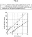
- Fig. 3 shows a correlation diagram obtained by plotting the data from the Examples arranged by the conditions for the root pass.
- the vertical axis of Fig. 3 represents the welding heat input Q (kJ/mm), and the horizontal axis of Fig. 3 represents the root gap G (mm).
- the groove angle ⁇ was 35° or less, and the root gap G was 7 to 15 mm.
- a welding wire (REM content: 0.015 to 0.100% by mass) was used, and the welding was performed with straight polarity. In this case, good penetration stability and the prevention of hot cracking were achieved simultaneously, and the adhesion of spatters to the walls of the groove could also be reduced.
- Examples with ⁇ marks in the correlation diagram in Fig. 3 are Comparative Examples.
- No. 20 the welding was performed while the welding current I, the welding voltage V, and the welding heat input Q were set within the root pass conditions described above.
- no backing material was used. In this case, the molten metal could not be held, so that the welding could not be performed.
Landscapes
- Engineering & Computer Science (AREA)
- Mechanical Engineering (AREA)
- Physics & Mathematics (AREA)
- Plasma & Fusion (AREA)
- Chemical & Material Sciences (AREA)
- Materials Engineering (AREA)
- Metallurgy (AREA)
- Organic Chemistry (AREA)
- Optics & Photonics (AREA)
- Arc Welding In General (AREA)
Applications Claiming Priority (2)
| Application Number | Priority Date | Filing Date | Title |
|---|---|---|---|
| JP2021044200 | 2021-03-18 | ||
| PCT/JP2022/010756 WO2022196541A1 (fr) | 2021-03-18 | 2022-03-11 | Procédé de soudage à l'arc sous protection gazeuse, joint soudé et procédé de production de joint soudé |
Publications (2)
| Publication Number | Publication Date |
|---|---|
| EP4269020A1 true EP4269020A1 (fr) | 2023-11-01 |
| EP4269020A4 EP4269020A4 (fr) | 2024-07-10 |
Family
ID=83320660
Family Applications (1)
| Application Number | Title | Priority Date | Filing Date |
|---|---|---|---|
| EP22771289.0A Pending EP4269020A4 (fr) | 2021-03-18 | 2022-03-11 | Procédé de soudage à l'arc sous protection gazeuse, joint soudé et procédé de production de joint soudé |
Country Status (6)
| Country | Link |
|---|---|
| US (1) | US20240149365A1 (fr) |
| EP (1) | EP4269020A4 (fr) |
| JP (1) | JP7327667B2 (fr) |
| KR (1) | KR102918432B1 (fr) |
| CN (1) | CN116917075A (fr) |
| WO (1) | WO2022196541A1 (fr) |
Families Citing this family (3)
| Publication number | Priority date | Publication date | Assignee | Title |
|---|---|---|---|---|
| US20240307990A1 (en) * | 2021-03-18 | 2024-09-19 | Jfe Steel Corporation | Gas-shielded arc welding method, welded joint, and method for producing welded joint |
| CN116652330A (zh) * | 2023-05-31 | 2023-08-29 | 江南造船(集团)有限责任公司 | 一种深熔弧焊接方法 |
| WO2025158721A1 (fr) * | 2024-01-25 | 2025-07-31 | Jfeスチール株式会社 | Procédé de soudage à l'arc sous protection gazeuse en intervalle horizontal étroit |
Family Cites Families (17)
| Publication number | Priority date | Publication date | Assignee | Title |
|---|---|---|---|---|
| JPS6017630B2 (ja) | 1976-12-28 | 1985-05-04 | 新日本製鐵株式会社 | 消耗電極式狭開先ア−ク溶接装置 |
| JPS62118975A (ja) | 1985-11-18 | 1987-05-30 | Kobe Steel Ltd | ア−ク溶接方法 |
| JP2745951B2 (ja) * | 1992-04-16 | 1998-04-28 | 日本鋼管株式会社 | 片面溶接における裏ビード制御方法 |
| JP3525977B2 (ja) * | 1996-07-17 | 2004-05-10 | 住友重機械工業株式会社 | 下向片面ガスシールドアーク溶接方法 |
| JP2000141031A (ja) | 1998-11-11 | 2000-05-23 | Nippon Steel Corp | 極厚鋼板の溶接方法 |
| KR100357723B1 (ko) * | 2000-09-27 | 2002-10-25 | 정무수 | 대입열 탄산가스 편면 용접용 세라믹 백킹재 |
| JP2007118068A (ja) | 2005-10-31 | 2007-05-17 | Jfe Steel Kk | 厚鋼板の狭開先突合せ溶接方法 |
| JP5345770B2 (ja) * | 2007-07-27 | 2013-11-20 | 株式会社神戸製鋼所 | チタニヤ系フラックス入りワイヤ |
| JP2008161943A (ja) * | 2008-01-31 | 2008-07-17 | Sunouchi:Kk | 溶接用セラミックス製エンドタブ |
| JP5314414B2 (ja) * | 2008-12-22 | 2013-10-16 | 株式会社神戸製鋼所 | フラックス入りワイヤ |
| CN101502816B (zh) * | 2009-03-06 | 2010-12-08 | 安徽凯照焊接新材料有限公司 | 含氧化锂的陶瓷焊接衬垫及生产方法 |
| JP6137053B2 (ja) * | 2014-05-27 | 2017-05-31 | Jfeスチール株式会社 | 狭開先ガスシールドアーク溶接方法 |
| CN108290239B (zh) * | 2015-12-04 | 2020-07-17 | 杰富意钢铁株式会社 | 立式窄坡口气体保护弧焊方法 |
| CN108367376B (zh) * | 2015-12-09 | 2020-07-17 | 杰富意钢铁株式会社 | 立式窄坡口气体保护弧焊方法 |
| WO2019182081A1 (fr) * | 2018-03-22 | 2019-09-26 | Jfeスチール株式会社 | Procédé de soudage à l'arc à protection gazeuse pour tôles d'acier |
| CN111761175A (zh) * | 2020-06-19 | 2020-10-13 | 武汉钢铁有限公司 | 一种厚板高效气渣联合保护焊接方法 |
| US20240307990A1 (en) * | 2021-03-18 | 2024-09-19 | Jfe Steel Corporation | Gas-shielded arc welding method, welded joint, and method for producing welded joint |
-
2022
- 2022-03-11 WO PCT/JP2022/010756 patent/WO2022196541A1/fr not_active Ceased
- 2022-03-11 US US18/279,800 patent/US20240149365A1/en active Pending
- 2022-03-11 EP EP22771289.0A patent/EP4269020A4/fr active Pending
- 2022-03-11 CN CN202280018840.3A patent/CN116917075A/zh active Pending
- 2022-03-11 JP JP2022528660A patent/JP7327667B2/ja active Active
- 2022-03-11 KR KR1020237030371A patent/KR102918432B1/ko active Active
Also Published As
| Publication number | Publication date |
|---|---|
| US20240149365A1 (en) | 2024-05-09 |
| JPWO2022196541A1 (fr) | 2022-09-22 |
| WO2022196541A1 (fr) | 2022-09-22 |
| CN116917075A (zh) | 2023-10-20 |
| JP7327667B2 (ja) | 2023-08-16 |
| KR20230137457A (ko) | 2023-10-04 |
| KR102918432B1 (ko) | 2026-01-29 |
| EP4269020A4 (fr) | 2024-07-10 |
Similar Documents
| Publication | Publication Date | Title |
|---|---|---|
| EP4269020A1 (fr) | Procédé de soudage à l'arc sous protection gazeuse, joint soudé et procédé de production de joint soudé | |
| JP6927304B2 (ja) | 鋼板のガスシールドアーク溶接方法 | |
| EP2489461B1 (fr) | Fil contenant un flux pour une soudure à l'arc sous scellement par un gaz, permettant une soudure dans toutes les positions | |
| CN108698175B (zh) | 药芯焊丝、焊接接头的制造方法和焊接接头 | |
| EP3539715B1 (fr) | Fil fourré, procédé de fabrication d'un joint soudé, et joint soudé | |
| EP1695785B1 (fr) | Structure soudee bout a bout avec apport de chaleur eleve presentant d'excellentes caracteristiques de resistance a l'apparition de rupture fragile | |
| EP2008754A1 (fr) | Gaz de protection pour soudage hybride et procédé de soudage hybride utilisant ledit gaz | |
| US20240307990A1 (en) | Gas-shielded arc welding method, welded joint, and method for producing welded joint | |
| JPWO2016143271A1 (ja) | 電縫溶接ステンレスクラッド鋼管およびその製造方法 | |
| CN108367376B (zh) | 立式窄坡口气体保护弧焊方法 | |
| CN109641306B (zh) | 立式窄坡口气体保护弧焊方法 | |
| EP4570410A1 (fr) | Procédé de soudage à l'arc de filet de recouvrement, et procédé de production de joint de soudage | |
| EP2883643A1 (fr) | Procédé de soudage à l'arc submergé, assemblage soudé formé par ledit procédé de soudage, et tube en acier présentant ledit assemblage soudé | |
| JP6119948B1 (ja) | 立向き狭開先ガスシールドアーク溶接方法 | |
| US20250100061A1 (en) | One-sided submerged arc welding method, weld joint, and production method for weld joint | |
| EP4737045A1 (fr) | Procédé de soudage à l'arc sous protection gazeuse à rainure étroite | |
| JP5268594B2 (ja) | I型継手の溶接方法及びそのi型溶接継手並びにそれを用いた溶接構造物 | |
| JPH09206945A (ja) | 多電極ガスシールド片面溶接方法 | |
| KR20030067569A (ko) | 서브머지드 아크 용접용 본드 플럭스 | |
| JP2002336982A (ja) | 薄板構造継手の複合溶接方法 | |
| JP4289616B2 (ja) | 鋼帯接合方法 | |
| JPH06285639A (ja) | クラッド鋼管の内面シーム溶接方法 | |
| Hadzihafizovic | Welding Imperfections and Material Inspection | |
| Hadzihafizovic | Weld Inspection for Structure Steel | |
| EP4670894A1 (fr) | Procédé de soudage à l'arc sous protection gazeuse à rainure étroite |
Legal Events
| Date | Code | Title | Description |
|---|---|---|---|
| STAA | Information on the status of an ep patent application or granted ep patent |
Free format text: STATUS: THE INTERNATIONAL PUBLICATION HAS BEEN MADE |
|
| PUAI | Public reference made under article 153(3) epc to a published international application that has entered the european phase |
Free format text: ORIGINAL CODE: 0009012 |
|
| STAA | Information on the status of an ep patent application or granted ep patent |
Free format text: STATUS: REQUEST FOR EXAMINATION WAS MADE |
|
| 17P | Request for examination filed |
Effective date: 20230725 |
|
| AK | Designated contracting states |
Kind code of ref document: A1 Designated state(s): AL AT BE BG CH CY CZ DE DK EE ES FI FR GB GR HR HU IE IS IT LI LT LU LV MC MK MT NL NO PL PT RO RS SE SI SK SM TR |
|
| DAV | Request for validation of the european patent (deleted) | ||
| DAX | Request for extension of the european patent (deleted) | ||
| A4 | Supplementary search report drawn up and despatched |
Effective date: 20240610 |
|
| RIC1 | Information provided on ipc code assigned before grant |
Ipc: B23K 35/38 20060101ALI20240604BHEP Ipc: B23K 103/04 20060101ALI20240604BHEP Ipc: B23K 9/23 20060101ALI20240604BHEP Ipc: B23K 9/173 20060101ALI20240604BHEP Ipc: B23K 9/035 20060101ALI20240604BHEP Ipc: B23K 9/025 20060101ALI20240604BHEP Ipc: C22C 38/04 20060101ALI20240604BHEP Ipc: C22C 38/02 20060101ALI20240604BHEP Ipc: C22C 38/00 20060101ALI20240604BHEP Ipc: B23K 35/30 20060101ALI20240604BHEP Ipc: B23K 9/16 20060101ALI20240604BHEP Ipc: B23K 37/06 20060101AFI20240604BHEP |