EP4269209A2 - Chariot roulant - Google Patents
Chariot roulant Download PDFInfo
- Publication number
- EP4269209A2 EP4269209A2 EP23170618.5A EP23170618A EP4269209A2 EP 4269209 A2 EP4269209 A2 EP 4269209A2 EP 23170618 A EP23170618 A EP 23170618A EP 4269209 A2 EP4269209 A2 EP 4269209A2
- Authority
- EP
- European Patent Office
- Prior art keywords
- trolley
- frame
- locking
- roof
- section
- Prior art date
- Legal status (The legal status is an assumption and is not a legal conclusion. Google has not performed a legal analysis and makes no representation as to the accuracy of the status listed.)
- Withdrawn
Links
Images


Classifications
-
- B—PERFORMING OPERATIONS; TRANSPORTING
- B62—LAND VEHICLES FOR TRAVELLING OTHERWISE THAN ON RAILS
- B62B—HAND-PROPELLED VEHICLES, e.g. HAND CARTS OR PERAMBULATORS; SLEDGES
- B62B3/00—Hand carts having more than one axis carrying transport wheels; Steering devices therefor; Equipment therefor
- B62B3/007—Coaster wagons
-
- B—PERFORMING OPERATIONS; TRANSPORTING
- B62—LAND VEHICLES FOR TRAVELLING OTHERWISE THAN ON RAILS
- B62B—HAND-PROPELLED VEHICLES, e.g. HAND CARTS OR PERAMBULATORS; SLEDGES
- B62B3/00—Hand carts having more than one axis carrying transport wheels; Steering devices therefor; Equipment therefor
- B62B3/02—Hand carts having more than one axis carrying transport wheels; Steering devices therefor; Equipment therefor involving parts being adjustable, collapsible, attachable, detachable or convertible
- B62B3/025—Foldable roll containers
-
- B—PERFORMING OPERATIONS; TRANSPORTING
- B62—LAND VEHICLES FOR TRAVELLING OTHERWISE THAN ON RAILS
- B62B—HAND-PROPELLED VEHICLES, e.g. HAND CARTS OR PERAMBULATORS; SLEDGES
- B62B3/00—Hand carts having more than one axis carrying transport wheels; Steering devices therefor; Equipment therefor
- B62B3/10—Hand carts having more than one axis carrying transport wheels; Steering devices therefor; Equipment therefor characterised by supports specially adapted to objects of definite shape
-
- B—PERFORMING OPERATIONS; TRANSPORTING
- B62—LAND VEHICLES FOR TRAVELLING OTHERWISE THAN ON RAILS
- B62B—HAND-PROPELLED VEHICLES, e.g. HAND CARTS OR PERAMBULATORS; SLEDGES
- B62B5/00—Accessories or details specially adapted for hand carts
- B62B5/0013—Protection covers, e.g. against rain
-
- B—PERFORMING OPERATIONS; TRANSPORTING
- B62—LAND VEHICLES FOR TRAVELLING OTHERWISE THAN ON RAILS
- B62B—HAND-PROPELLED VEHICLES, e.g. HAND CARTS OR PERAMBULATORS; SLEDGES
- B62B5/00—Accessories or details specially adapted for hand carts
- B62B5/06—Hand moving equipment, e.g. handle bars
- B62B5/067—Stowable or retractable handle bars
-
- B—PERFORMING OPERATIONS; TRANSPORTING
- B62—LAND VEHICLES FOR TRAVELLING OTHERWISE THAN ON RAILS
- B62B—HAND-PROPELLED VEHICLES, e.g. HAND CARTS OR PERAMBULATORS; SLEDGES
- B62B2205/00—Hand-propelled vehicles or sledges being foldable or dismountable when not in use
- B62B2205/06—Foldable with a scissor-like mechanism
-
- B—PERFORMING OPERATIONS; TRANSPORTING
- B62—LAND VEHICLES FOR TRAVELLING OTHERWISE THAN ON RAILS
- B62B—HAND-PROPELLED VEHICLES, e.g. HAND CARTS OR PERAMBULATORS; SLEDGES
- B62B2205/00—Hand-propelled vehicles or sledges being foldable or dismountable when not in use
- B62B2205/20—Catches; Locking or releasing an articulation
- B62B2205/24—Catches; Locking or releasing an articulation to hold in the folded position
Definitions
- the present invention relates to a trolley comprising a frame, a loading area which is supported on the frame, at least one wheel which is designed to enable movement of the trolley relative to a floor surface, and a handle which is connected via a handle bar is attached to the frame so that the trolley can be pushed or pulled over the floor surface.
- Trolleys of this type are known from the prior art, particularly for transporting goods.
- a trolley is often pulled by a person who is in front of the trolley. Alternatively, such a trolley can also be pushed.
- a corresponding trolley prefferably includes a roof which can be removably attached to a frame of the trolley.
- the roof serves in particular to protect the loading area itself and the goods being transported from wind, rain and sunlight.
- telescopic fastening elements are often provided, which in an initial state are sunk into the frame of the trolley and can be pulled out of the frame to clamp the roof.
- the trolley described should not only be usable on flat terrain, such as asphalted roads, but also on uneven terrain, such as on the beach or on walking paths, particularly robust or stable trolleys are desirable. It has been shown that the use of plastic rods as fastening elements for the roof may lead to insufficient stability of the fastening elements. This can happen, for example, in strong winds or when driving through one Potholes can cause such a fastening element to bend or, in the worst case, even break off. One solution to this would be to make the fastening elements or the trolley itself smaller overall, which would, however, save valuable storage space.
- a trolley comprising a frame; a loading surface which is supported on the frame; at least one wheel adapted to enable movement of the trolley relative to a floor surface; a handle attached to the frame via a handle bar; a roof adapted to be removably attached to the frame to cover the cargo area; and at least one fastener for fastening the roof to the frame, the fastener having a first end adapted to be fastened to the frame and a second end adapted to be fastened to the roof; wherein the fastening element comprises a tube section which is displaceable relative to the frame, the trolley further comprising a folding mechanism by means of which the trolley can be transferred from an operating configuration to a folded configuration and vice versa, and the trolley further comprising a locking mechanism, which is configured to automatically lock the cart in the folded configuration when the cart is transferred from the operational configuration to the folded configuration.
- the operating configuration is the configuration in which the trolley is operational, i.e. can be used for the purposes described above.
- the folded configuration is a configuration in which the trolley is folded or collapsed, in particular in order to be able to be stored in a space-saving manner. For example, it is preferred to transport the trolley in the folded configuration in a trunk of a car or to store it in a storage room.
- the folding mechanism which is designed to be reversible so that the trolley can be transferred from the operating position to the folded configuration and vice versa, preferably enables the trolley to be folded symmetrically.
- the folding mechanism can in particular be designed centrally with respect to the main extension direction of the trolley, so that in particular the frame of the trolley is folded in equal parts on both sides, starting from the center of the trolley.
- the cart includes a locking mechanism which serves to lock the cart in the folded configuration.
- a locking mechanism which serves to lock the cart in the folded configuration.
- Such a locking mechanism can ensure that the trolley remains in the folded configuration and does not unfold in an undesirable manner.
- a user of the trolley can therefore concentrate purely on stowing the trolley.
- the locking mechanism of the present invention is that the trolley locks automatically, ie without any additional action by the user, when folding, i.e. when transferring from the operating configuration to the folded configuration. Accordingly, the user can fold the trolley with both hands, without having to pay attention to the locking mechanism being activated or triggered. This makes handling the trolley easier for the user.
- the frame can have a plurality of joint elements, with one joint element connecting two first frame elements of the frame to one another in such a way that the frame elements can be folded about a folding axis which runs orthogonally to the main extension direction of the trolley, and where the joint elements and the frame elements define the folding mechanism.
- a joint element can be designed, for example, as a hinge, at each of whose opposite ends a frame element is arranged.
- Corresponding frame elements are preferably designed parallel to the main extension direction of the trolley and thus extend along the two long sides of the frame of the trolley.
- the folding axis runs orthogonally to the frame elements.
- a tab or a handle can be provided on the loading area or the frame of the trolley, by means of which the user can fold the frame elements about the folding axis.
- a linkage can be provided, which runs along the folding axis and is connected to the joint elements on both sides with respect to the two long sides of the frame.
- the locking mechanism can comprise a first locking element and a second locking element, wherein the two locking elements can be designed to be complementary to one another.
- each locking element is preferably arranged on an elongated frame element, wherein the corresponding frame elements are each arranged at one of the two opposite ends of a joint element.
- the locking elements are designed to be rigid and do not change their position relative to the frame element on which they are arranged during the folding of the trolley. In order to lock the trolley in the folded configuration by means of the two locking elements, it may be sufficient to provide the two locking elements on only one long side of the frame. Alternatively, however, several locking elements and corresponding frame elements and joint elements can also be provided on one long side or both long sides of the frame.
- the two locking elements can be made of plastic, for example, in order not to unnecessarily increase the weight of the trolley. However, it is also possible to produce the locking elements from a different material, for example metal.
- the two locking elements may be arranged on the frame such that when the trolley is transferred from the operating configuration to the folded configuration, they engage one another to lock the trolley in the folded configuration.
- the two locking elements can each be provided on a frame element on a long side of the frame.
- the two corresponding frame elements can pivot about the folding axis and thereby come closer to one another, so that the two locking elements move towards one another and engage with one another.
- this intervention takes place automatically, i.e. purely by folding the trolley, without the user having to actuate the locking mechanism in any way.
- the first locking element may comprise a slot and a recess, the recess being formed orthogonally to the slot, the second locking element comprising an extension and a displaceable section which is formed on the extension, and wherein the Extension of the second locking element is designed to be insertable into the slot of the first locking element when transferring the trolley into the folded configuration, so that the displaceable section of the second locking element engages with the recess of the first locking element.
- the slot of the first locking element and the extension of the second locking element can in particular be aligned parallel to the elongated frame elements, so that the extension can easily slide into the slot when the trolley is folded in order to establish the engagement between the two locking elements.
- the dimensions of the slot and the extension as well as the recess and the displaceable section are preferably each designed to be complementary to one another.
- the displaceable section of the second locking element can have an inclination with respect to the extension, so that the displaceable section protrudes at least in sections over the extension.
- the inclination of the displaceable section can in particular be designed such that it increases steadily starting from a front end of the second locking element, on which the displaceable section is designed to be essentially flat with the extension.
- the front end of the second locking element is a section of the extension which penetrates into the slot of the first locking element during the engagement between the first and second locking elements.
- the displaceable section abuts the lateral boundary of the slot due to its inclination and is then displaced towards the interior of the extension, so that the folding of the trolley produces a displacement or actuation of the displaceable section.
- the lateral boundary of the slot remains continuously in contact with the inclined displaceable section until it is completely received in the recess of the first locking element and locked therein. This process represents the engagement between the first and the second Locking element and thus the locking of the trolley in the folded configuration.
- a restoring element can be formed inside the extension of the second locking element, which is designed to exert a restoring force on the displaceable section in order to return the displaceable section to a starting position in response to an actuation of the displaceable section.
- the restoring element for example a restoring spring, can exert a force on the displaceable section, which acts in particular against the previously described actuation or displacement of the displaceable section through the lateral boundary of the slot. Consequently, the restoring element causes the displaceable section to be displaced into its starting position after the displaceable section is completely received in the recess of the first locking element, i.e. when the lateral boundary of the slot no longer contacts the displaceable section.
- the starting position of the displaceable section is to be understood as meaning the position of the displaceable section which it occupies in the operating configuration of the trolley.
- the engagement of the first and second locking elements may be releasable by actuating the displaceable portion of the second locking element, so that the trolley can be transferred from the folded configuration to the operating configuration.
- the displaceable section can be displaced from the recess of the first locking element by the user, for example with a finger, pressing the displaceable section against the restoring force of the restoring element towards the interior of the extension and at the same time unfolding the folded frame of the trolley.
- the extension of the second locking element can be displaced from the slot in the first locking element and the trolley can be transferred to the operating configuration.
- the locking mechanism provides This provides the user of the trolley with an easy way to transfer the trolley from the folded configuration back to the operating configuration.
- the at least one fastening element for fastening the roof to the frame optionally comprises one or more pipe sections which are mounted displaceably with respect to the frame.
- a section of pipe provides a secure connection between the frame and the roof.
- the tubular shape of the pipe section ensures its structural stability, which also increases the stability of the roof.
- the pipe section is mounted so that it can move with respect to the frame, which means that different configurations of the trolley can be achieved in a simple manner. For example, the height of the roof can be adjusted by moving the pipe section.
- the pipe section can be transferred to a position in which it is stowed in the frame, particularly if the roof has been removed. Accordingly, the pipe section is connected to the frame via the fastening element even if no roof is attached to the trolley. Furthermore, it is provided that the pipe section is largely or even completely integrated into the frame in the stowed position.
- the stability of the roof attached to the pipe section is significantly dependent on the stability of the pipe section.
- a pipe section with an increased diameter in particular has a positive effect on its stability and therefore also on the roof.
- the pipe section optionally has a diameter which is greater than 1 cm, preferably greater than 2 cm.
- the pipe section is handy and easy to use.
- the pipe section of the present invention therefore particularly preferably has a diameter between 2 cm and 4 cm.
- the fastening element can comprise a locking unit which is designed to lock the pipe section in a locking position, the pipe section comprising at least one locking element complementary to the locking unit along its main extension direction.
- the pipe section can be locked in at least two locking positions relative to the frame by the locking element, whereby the height of the roof attached to the pipe section can be adjusted by means of the locking unit in conjunction with the locking positions. For example, it may be desirable to set the roof to a low locking position if there are only flat objects in the trolley. On the other hand, the roof can be adjusted to a higher locking position when larger items are transported in the trolley.
- a base locking position can be provided in which the pipe section is completely or largely stowed in the frame of the trolley. It may well be expedient for the roof to be attachable to the trolley even in a state in which the pipe section is in the basic locking position.
- the pipe section can be released in its respective locking position and then relocated to another locking position.
- the locking element of the pipe section is designed, for example, in the form of a plurality of notches in the pipe section, each notch representing a locking position.
- the pipe section can be made of a metal, preferably aluminum. This can increase the stability and strength of the fastener become.
- a sufficiently high stability of the fastening element can be achieved without significantly increasing the weight of the trolley, for example in comparison to a pipe section made of plastic.
- Stainless steel is particularly suitable for producing the pipe section.
- a metallic pipe section is also particularly suitable for not bending or breaking even in strong winds, which also increases the stability of the roof.
- the resistance of the fastening element to vibrations can be improved, whereby corresponding vibrations can occur in particular when the trolley is moved over uneven terrain or, for example, through potholes.
- a trolley comprising a frame; a loading surface which is supported on the frame; at least one wheel adapted to enable movement of the trolley relative to a floor surface; a handle attached to the frame via a handle bar; a roof adapted to be removably attached to the frame to cover the cargo area; and at least one fastener for fastening the roof to the frame, the fastener having a first end adapted to be fastened to the frame and a second end adapted to be fastened to the roof; wherein the fastening element comprises a tube section which is displaceable relative to the frame, wherein a linkage is arranged on the handle bar, which is pivotally mounted on the frame and is designed to transfer a force acting laterally on the handle bar to the frame.
- the handle bar of the trolley according to the second aspect of the present invention is stabilized by a linkage.
- the linkage is in engagement with the handlebar, for example centrally in relation to the main direction of extension of the handlebar. If a telescopic handlebar is used, it can be slidably or telescopically engaged with the linkage.
- the linkage extends, starting from the handle bar, in particular to the frame of the trolley and can be pivotally connected to it. Consequently, forces acting laterally on the handle bar can be transferred to the frame via the linkage.
- the linkage can be pivoted together with the handlebar about a common pivot axis, which runs, for example, parallel to an end face of the trolley.
- the linkage can have a first section and a second section, the first section and the second section extending from the handle bar in the opposite direction to the frame.
- the linkage can be designed in two parts and extend on both sides from the handlebar in the direction of the frame, wherein the two parts or the first and second sections of the linkage can be connected to one another on the handlebar by a connecting element.
- the linkage can have a diameter which is greater than 1 cm, preferably greater than 1.5 cm, and particularly preferably between 1.5 cm and 3 cm.
- a diameter of 1 cm or larger serves in particular to increase the strength of the linkage and thus its resistance to shocks and vibrations.
- a trolley comprising a frame; a loading surface which is supported on the frame; at least one wheel adapted to enable movement of the trolley relative to a floor surface; a handle attached to the frame via a handle bar; a roof adapted to be removably attached to the frame to cover the cargo area; and at least one fastener for fastening the roof to the frame, the fastener having a first end adapted to be fastened to the frame and a second end adapted to be fastened to the roof; wherein the fastening element comprises a tube section which is displaceable relative to the frame, wherein at least one pocket is arranged on the frame, which is pivotally mounted on the frame via at least one pivoting unit and pivotable between an operating position in which a receiving area of the pocket is completely released is, and a stowed position in which the recording area is only partially exposed.
- the bag serves in particular as additional storage space for objects which, for example, are to be transported separately from objects located on the loading area.
- the bag may be provided in either the operating position or the stowed position, with a user of the cart being able to transfer the bag from the operating position to the stowed position and vice versa at any time.
- objects can be stored in the bag both in the operating position and in the stowed position, with the bag preferably having a larger storage space in the operating position.
- the receiving area of the bag can be accessible in both positions, so that objects can be placed in the bag or removed from the bag via the receiving area.
- a cover can also be attached to the bag, by means of which the receiving area can be closed, for example to protect the contents of the bag from rain.
- the bag can be arranged on a side of the frame facing away from the loading area.
- the bag can be provided on the frame in such a way that it is easily accessible from the outside for the user of the trolley. This has the particular advantage that the pivotability of the bag is not impaired by objects inside the trolley.
- the bag can also be arranged on the inside of the frame of the trolley.
- the operating position and the stowed position of the bag can optionally be formed at an angle of approximately 90° to one another.
- the receiving area of the pocket in the operating position is designed essentially parallel to an axial main extension direction of the trolley. This can ensure that the user can place objects in the bag or remove them from the bag as easily as possible.
- the entire volume of the bag is preferably as close as possible to the frame of the trolley, so that the overall circumference of the trolley is not or only slightly increased by a bag attached to the outside of the frame of the trolley.
- the pivoting unit can comprise a pivoting mechanism which is set up to enable the bag to be transferred from the operating position to the stowed position and vice versa by manual operation of the bag.
- the pivoting mechanism preferably includes at least two locking positions, wherein a first locking position can be provided for the operating position and a second locking position can be provided for the stowed position. If the bag is now, for example, in the stowed position, the user can move the bag from the first locking position into the second locking position and thus into the operating position by actuating the pivoting mechanism, the transfer essentially consisting of one Pivoting the bag about a pivot axis consists.
- only one locking position can be formed, which defines the operating position of the bag. In this case, the bag is not locked in the stowed position and can therefore be moved without operating the pivoting mechanism.
- the trolley optionally further comprises at least one actuating element which has a release position and a locking position and is coupled to the wheel in such a way that the wheel can be rotated about an axis of rotation in the release position and that the rotation of the wheel is locked in the locking position.
- at least one actuating element which has a release position and a locking position and is coupled to the wheel in such a way that the wheel can be rotated about an axis of rotation in the release position and that the rotation of the wheel is locked in the locking position.
- the actuating element serves in particular to lock or block the wheel of the trolley so that it can also be parked on uneven terrain. This means that the user of the trolley generally transfers the actuating element from the release position to the locked position in order to turn off or park the trolley.
- at least one actuating element can also be designed as a brake, which is preferably arranged near the handle or the handle bar and enables the user to brake the trolley while driving.
- the actuating element can be formed on a wheel suspension, on the wheel or on the frame.
- a wheel suspension on the wheel or on the frame.
- one of the configurations mentioned may be advantageous.
- an actuating element provided on the wheel or on the wheel suspension would be difficult for the user to reach.
- the actuating element can be moved from the release position into by manual actuation the locking position and vice versa can be transferred.
- it is preferably designed with a tread surface that the user can easily reach with their foot.
- the tread surface can be displaceable between two positions, with a first position corresponding to the release position and a second position corresponding to the blocking position.
- the actuating element can also include a handle instead of the tread surface.
- the trolley can in particular comprise a plurality of wheels, preferably four wheels, and a plurality of actuating elements, each wheel being coupled to one actuating element.
- actuating elements each wheel being coupled to one actuating element.
- each actuating element can be actuated individually or together via an actuating mechanism. Consequently, the user of the trolley can also lock or unlock each wheel individually.
- a central actuating element can be provided, which is coupled to all the wheels of the trolley.
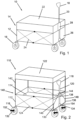
- a trolley according to the invention according to a first exemplary embodiment is designated by reference number 10.
- the trolley 10 comprises a frame 12, which holds a loading area 14 in its interior, and four wheels 16, of which, based on the perspective view in Figure 1 only three wheels 16 are visible.
- the wheels 16 are designed in particular to enable the trolley 10 to be moved on or over a floor surface.
- the trolley 10 includes a handle 18, which is connected to the frame 12 via a handle bar 20, and a roof 22, which is removably attached to the frame 12 and in particular covers the loading area 14. Since the roof 22 is designed here in a lowered position, the loading area 14 in Figure 1 completely covered by the roof 22 and is therefore only indicated.
- the frame 12 and the loading area 14 can, for example, be set up to accommodate a payload of up to 60 kg, whereby the payload can be goods to be transported.
- the frame 12 and the loading area 12 are designed such that a higher payload can be transported.
- the frame 12 is in particular formed by a plurality of elongated frame elements 24, which are suitable for being connected to one another to form the substantially rectangular loading area 14.
- the loading area 14 and the roof 22 are preferably made of a light and flexible material, for example a textile material.
- the loading area 14 includes side walls 26, so that objects that are transported in the trolley 10 cannot easily fall out of the trolley 10.
- the rectangular configuration of the frame 12 and the loading area 14 shown here is merely an example, so that other configurations are also possible, for example a triangular or oval configuration.
- Figure 1 shows that a section 28 that overlaps the handle bar 20 is formed on an end face of the roof 22 facing the handle bar 20.
- the overlapping section 28 can, for example, have a Velcro fastener (not shown), by means of which the overlapping section 28 can be released on one side in order to hold the handle bar 20 in the to accommodate overlapping section 28 and thus secure it.
- the use of the overlapping section 28 to secure the handle bar 20 can be advantageous for a user of the trolley 10, particularly if the user wants to put down or park the trolley 10.
- the wheels are 16 in Figure 1 arranged in pairs on a front axle and a rear axle (not shown) of the trolley 10, the two wheels 16 of the front axle being offset inwards, while the wheels 16 of the rear axle are each arranged at a lateral end of the rear axle.
- the front axle of the trolley 10 is arranged, for example, on the same side as the handle 18 or the handle bar 20, whereby a forward movement of the trolley 10 can be achieved by pulling the trolley 10 using the handle 18 can.
- a trolley 110 according to a second exemplary embodiment is now shown with a raised or extended roof 122.
- the trolley 110 of the second exemplary embodiment differs from the trolley 10 of the first exemplary embodiment, on the one hand, by the positioning of the roof 122 and, on the other hand, by the arrangement of a linkage 130, which is connected to a frame 112 and a handle bar 120.
- each wheel 116 of the trolley 110 includes an actuating element 132, the actuating element 132 being coupled to the wheel such that the wheel 116 is either in a release position or in a locking position.
- a handle 118 is pivotally attached to the frame 112 via the handle bar 120, with a first hinge 134 being designed to enable the handle bar 120 to be pivoted about a pivot axis 136, which runs orthogonally to a main extension direction of the trolley 110.
- the handle 118 can be moved between one in. via the first hinge 134 Figure 2 shown upright position and a position essentially close to the ground. The user is thereby able to adjust an orientation or a height of the handle 118 according to his or her preferences for pulling or pushing the trolley 110.
- a holding element 138 can also be formed, which is provided, for example, on a transverse, elongated frame element 124.
- Such a holding element 138 in particular a clamp or a locking element, serves here to secure the handle bar 120 in the upright position of the handle 118 and thus fulfills the function of the with respect to Figure 1 described overlapping section 28.
- a loading area 114 is held on an inside of the frame 112 and thereby enables the transport of objects inside the trolley 110.
- a fastening element 140 is provided at each corner of the frame 112, which is designed to enable the roof 122 to be fastened to the frame 112.
- the fastening element 140 includes a telescopic tube section 142, at the upper end of which the roof 122 is attached.
- the fastening element 140 or its tube section 142 is connected on one side to the frame 112, wherein the tube section 142 can preferably be completely sunk into the frame 112, for example in order to Figure 1 to achieve the configuration of the roof 22 shown.
- Pipe sections 142 shown in particular have a diameter of at least 1 cm in order to achieve high stability of the respective pipe section 142 or the corresponding fastening element 140.
- the stability of the pipe sections 142 has a positive effect on the resistance of the roof 122 to wind and/or vibrations, which can be generated in particular when driving over uneven terrain.
- the diameters of the pipe sections 142 do not exceed 4 cm in order not to complicate the handling of the fastening elements 140 and the attachment of the roof 122 and in order not to excessively increase the weight of the trolley 110.
- both the fastening elements 140 including their respective pipe section 142 as well as the frame 112 and the linkage 130 are made of a metal, preferably aluminum, which ensures high stability of the trolley 110 while maintaining a moderate weight.
- the linkage 130 shown is in particular designed to transfer forces acting laterally on the handle bar 120, which are generated, for example, when the trolley is cornering, to the frame 112 and thus to relieve the load on the handle bar 120.
- the linkage 130 is connected to the handle bar 120 via a connecting element 144, which is arranged, for example, halfway up the handle bar 120.
- the connecting element 144 is designed such that the telescopic handle bar 120 is slidably mounted in the connecting element 144 along its main extension direction and is nevertheless supported laterally, ie orthogonally to a main extension direction of the trolley 110, by the connecting element 144.
- Two sections 146, 148 of the linkage 130 extend from the connecting element 144 in the direction of a front axle of the trolley 110 or in the direction of the pivot axis 136.
- the two sections 146, 148 extend here in essentially opposite directions from the connecting element 144 in the direction of Front axle of the trolley 110, so that the first section 146 contacts the frame 112 in the area of the right front wheel 116 and the second section 148 contacts the frame 112 in the area of the left front wheel 116.
- the two sections 146, 148 are also connected to the frame 112 via a second hinge 150, so that the pivotability of the handle bar 120 relative to the frame 112 is not affected by this Linkage 130 is affected.
- Figure 2 also illustrates that an actuating element 132 is formed on each of the wheels 116 of the trolley 110, which here has a tread surface 152.
- the actuating element 132 is coupled to a respective wheel 116 in such a way that the wheel 116 is either in a release position, in which the wheel 116 can rotate so that the trolley 110 can move or be moved relative to a floor surface, or in a locked position , whereby the wheel 116 can be locked or blocked, for example, to the trolley 110 can also be parked on inclined surfaces.
- the tread surface 152 can be designed as a lever or have a lever function.
- the user of the trolley 110 is thereby able to conveniently move the actuating element 132 over the tread surface 152, for example by actuating the tread surface 152 with his foot or with his hand to bring about the desired position.
- a toothed ring (not shown), for example, can be arranged on the side of the wheel 116.
- a pin (not shown) is formed on the actuating element 132, complementary to the toothed ring, which engages in the toothed ring during the transfer of the actuating element 132 from the release position to the locked position and thereby blocks the rotation of the wheel 116.
- a single actuator 132 is provided on each wheel 116, as shown in FIGS Figures 2 and 3 shown.
- an actuating element 132 can also be provided, which is coupled to a plurality of wheels 116.
- a corresponding actuating element 132 can be arranged, for example, on the frame 112 and coupled to the wheels 116 via an additional linkage (not shown).
- an actuation mechanism can be provided here, which enables individual wheels 116 to be adjusted or all wheels 116 to be adjusted together.
- the actuating element 132 can also be arranged on a wheel suspension 154 or, as already mentioned, for example also on the frame 112.
- the wheels 116 attached to the front axle of the trolley 110 are designed to be pivotable on the front axle, the pivotability of the wheels 116 being justified in particular by the pivotably mounted wheel suspension 154.
- the wheels 116 can be pivoted orthogonally to the main direction of extension of the trolley 110, so that the trolley 110 is in the Is able to drive curves, whereby cornering can be caused, for example, by a force acting laterally on the frame 112 and / or the handle 118.
- the rear wheels 116 can also be pivotally mounted analogous to the front wheels 116.
- the two inwardly offset wheels 116 correspond to the front wheels and the two outwardly offset wheels 116 correspond to the rear wheels, this configuration being merely exemplary.
- a trolley 210 is illustrated according to a third exemplary embodiment.
- the trolley is 210 in Figure 4 shown in a perspective view with a raised roof 222, while in Figure 5 a partial section of the trolley 210 is shown.
- the trolley 210 of the third exemplary embodiment differs from the trolley 110 of the second exemplary embodiment only in that a pivotable pocket 256 is provided on a frame 212.
- the pocket 256 is arranged here on a rear end face of the trolley 210 and on the outside of the frame, so that this pocket 256 is more easily accessible from the outside for the user of the trolley 210.
- the pocket 256 can also be arranged at a different position on the frame 212 and in particular also on the inside of the frame, ie pointing towards a loading area 214.
- the user of the trolley 210 can store objects in the bag 256 that are to be transported separately from the objects located on the loading area 214.
- the pocket 256 has a receiving area 258 through which objects can be placed in the pocket 256 or removed from the pocket 256.
- the pocket 256 is preferably open at the top so that objects cannot easily fall out of the pocket 256 even in the event of vibrations.
- the bag 256 is mounted on the frame 212 via a pivot unit 260 so that it can be pivoted about a pivot axis 262.
- an operating position 256a of the pocket 256 is provided, which is in Figure 4 is shown and in which the recording area 258 is fully released, i.e. accessible to the user.
- the bag 256 can be transferred to a stowed position 256b, which is in Figure 5 is illustrated. Objects can also be placed in the pocket 256 in the stowed position 256b, but the existing storage volume in the stowed position 256b is significantly reduced compared to the operating position 256a. This results from the transfer of the bag 256 from the operating position 256a to the stowed position 256b, since the bag 256 is pivoted by approximately 90 ° about the pivot axis 262 and consequently lies closer or tighter to the frame 212, thereby increasing the storage volume of the bag 256 is compressed by the frame 212.
- the bag 256 is made of a textile material that has high elasticity, so that the bag 256 can be reversibly compressed.
- the pivoting unit 260 of the bag 256 includes a pivoting mechanism that allows the bag 256 to be transferred from the operating position 256a to the stowed position 256b and vice versa.
- the pocket 256 In the operating position 256a, the pocket 256 is locked or locked so that it remains constantly in the operating position 256a even while the trolley 210 is moving. If the user now wants to move the bag 256 into the stowed position 256b, he can only do this after releasing the lock.
- the pivot mechanism of the pivot unit 260 is designed such that the locking can be released by moving the pocket 256 upwards, ie by pivoting the pocket 256 about the pivot axis 262 in the opposite direction relative to the stowed position 256b.
- the pocket 256 can be lowered to open the in Figure 5 to reach the state shown and to assume the stowed position 256b.
- the pivoting mechanism relaxes so that the bag 256 can lock when transferred again from the stowed position 256b to the operating position 256a.
- the pivot unit 260 is preferably provided in the form of a torque or locking hinge.
- FIG. 6 again shows the trolley 119 of the second exemplary embodiment, which is now shown without a roof 122.
- a fastening element 140 includes a first end 141, via which the fastening element 140 is connected to the frame 112.
- an end section 174 of a pipe section 142 is illustrated, with the end section 174 defining a second end of the fastening element 140.
- the end section 174 is preferably flat, so that the roof 122 can be placed over the end section 174 as easily as possible.
- the fastening element 140 including pipe section 142 is in Figure 7 shown in a detailed view, from which it can be seen that the fastening element 140 has an enlarged diameter at its first end 141, at which the fastening element 140 is connected to the frame 112, compared to the pipe section 142.
- the tube section 142 which is illustrated here in an extended configuration, can thereby be retracted into the fastening element 140 as well as into the frame 112, in particular around the in Figure 1 to achieve the configuration shown.
- the fastening element 140 and the frame 112 are hollow in the affected section.
- the fastening element 140 comprises a locking unit 170. Furthermore, on the pipe section 142 there is at least one locking element 176 which is complementary to the locking unit 170 , which is designed, for example, in the form of a notch.
- the locking unit 170 engages in each locking element 176 inside the fastening element 140, for example through a pin, and thus secures the pipe section 142 in the corresponding locking position, for example in the in Figure 7 extended configuration shown.
- the user of the trolley 110 now wants to change the locking position of the pipe section 142 and move the pipe section 142 relative to the frame 112, he can do this by actuating the locking unit 170 and at the same time manually pulling out or pushing the pipe section 142 out of or into the fastening element 140 to reach.
- the locking unit 170 By activating the locking unit 170, the locking element 176 of the Pipe section 142 released and thus allows the pipe section 142 to be relocated. So it is particularly advantageous when using the trolley 110 without a roof 122 to move the pipe section 142 into a basic locking position in which the pipe section 142 is almost completely stowed in the fastening element 140 or in the frame.
- the trolley 110 is equipped with a reversible folding mechanism 178, which enables the trolley 110 to be stored in a space-saving manner, and further a locking mechanism 180, which enables the trolley 110 to be locked in a folded configuration.
- the frame 112 is formed with a plurality of joint elements 147, which are provided on both sides of the frame 112 along the main extension direction of the trolley 110.
- these joint elements 147 each connect two elongated frame elements 124, so that the trolley 110 can be folded or folded symmetrically.
- a handle or a loop (not shown) can be formed centrally on the loading area 114, by means of which the user can fold the trolley 110. Furthermore, due to the folding mechanism 178, the front wheels 116 are arranged offset from the rear wheels so that they do not collide with each other when folded.
- the folding mechanism 178 and the locking mechanism 180 are described below using the Figures 8a, 8b and 9a and 9b explained in more detail.
- the folding mechanism 178 includes the elongated tubular elements 124, which extend on the long sides of the frame of the trolley, as well as the joint elements 147. These are each in the Figures 8a and 9a illustrated.
- a linkage (not shown) runs between the two long sides of the frame 112, which represents the underbody of the frame and extends along the main direction of extension of the trolley 110.
- folding mechanism 178 If the folding mechanism 178 is actuated by the user, adjacent ones and those connected via a joint element 147 fold or fold Frame elements 124 together with the linkage about a folding axis which extends orthogonally to the main extension direction of the trolley between two joint elements 147, the corresponding joint elements 147 being formed on the two long sides.
- the first locking element 182 comprises a slot 186 which is arranged parallel to the movement or folding direction of the frame elements 124, so that an extension 190 of the second locking element 184 can be accommodated in the slot.
- the first locking element 182 further includes a recess 188 which is formed orthogonally to the slot 186 and serves to receive a displaceable portion 192 of the second locking element 184 in order to lock the second locking element 184 in the first locking element 182.
- Figure 8b represents a state which the Figure 8a corresponds, that is, the two locking elements 182, 184 are in an unlocked state, i.e. in particular in the operating configuration of the trolley 110.
- the two locking elements 182, 184 engage with one another when the trolley 110 is moved from the operating configuration to the folded configuration is transferred.
- the extension 190 of the second locking element 184 first penetrates into the slot 186 of the first locking element 182.
- an inclined displaceable section 192 of the second locking element 184 contacts the lateral boundary of the slot 186, the inclination of the displaceable section 192 being such is designed so that a substantially flat part of the displaceable section 192, ie flat to the remaining extension 190, points in the direction of the slot 186.
- the displaceable section 192 is received in the slot 186 and a force is exerted on the inclined surface of the displaceable section 192 due to the contact with the lateral boundary of the slot 186.
- the displaceable section 192 is then displaced into a recess (not shown) inside the extension 190 and thus clears the way for the second locking element 184 into the slot 186.
- the second locking element 184 can be inserted into the slot 186 until the displaceable section 192 completely overlaps the recess 188 which is in the Figures 8b and 9b is indicated by a dashed line in the lateral boundary of the slot 186.
- a restoring element for example a restoring spring (not shown), is also formed inside the extension 186, which forces the displaceable section 192 into the recess 188.
- the displaceable portion 192 automatically locks or locks the second locking element 184 when the trolley 110 is transferred from the operating configuration to the folded configuration. The user therefore does not have to actively operate the locking mechanism 180 to lock the trolley, which means that both hands are available for folding the trolley.
- the state of the locking elements 182, 184 in the folded configuration is in the Figures 9a and 9b illustrated.
- the user can press the inclined surface of the displaceable section 192 towards the interior of the extension 190 against the restoring force of the restoring element and at the same time push the second locking element 184 out of the slot 186 of the first locking element 182, for example by grabbing two of the frame elements 124 and pulling them in opposite directions.
Landscapes
- Engineering & Computer Science (AREA)
- Chemical & Material Sciences (AREA)
- Combustion & Propulsion (AREA)
- Transportation (AREA)
- Mechanical Engineering (AREA)
- Handcart (AREA)
Applications Claiming Priority (1)
| Application Number | Priority Date | Filing Date | Title |
|---|---|---|---|
| DE202022102336.0U DE202022102336U1 (de) | 2022-04-29 | 2022-04-29 | Rollwagen |
Publications (2)
| Publication Number | Publication Date |
|---|---|
| EP4269209A2 true EP4269209A2 (fr) | 2023-11-01 |
| EP4269209A3 EP4269209A3 (fr) | 2024-01-10 |
Family
ID=81749959
Family Applications (1)
| Application Number | Title | Priority Date | Filing Date |
|---|---|---|---|
| EP23170618.5A Withdrawn EP4269209A3 (fr) | 2022-04-29 | 2023-04-28 | Chariot roulant |
Country Status (2)
| Country | Link |
|---|---|
| EP (1) | EP4269209A3 (fr) |
| DE (2) | DE202022102336U1 (fr) |
Family Cites Families (4)
| Publication number | Priority date | Publication date | Assignee | Title |
|---|---|---|---|---|
| IT206571Z2 (it) * | 1986-04-23 | 1987-08-10 | Perego Pines Gmbh | Passeggino pieghevole perfezionato per bambini. |
| JP4689018B2 (ja) * | 2000-09-21 | 2011-05-25 | コンビ株式会社 | ツインタイプベビーカー |
| US9085311B1 (en) * | 2014-10-03 | 2015-07-21 | Zhaosheng Chen | Folding wagon with canopy |
| US11225277B1 (en) * | 2021-01-11 | 2022-01-18 | Zhejiang Pride Leisure Products Co., Ltd. | Double-cross cart |
-
2022
- 2022-04-29 DE DE202022102336.0U patent/DE202022102336U1/de active Active
-
2023
- 2023-04-28 DE DE202023106749.2U patent/DE202023106749U1/de active Active
- 2023-04-28 EP EP23170618.5A patent/EP4269209A3/fr not_active Withdrawn
Also Published As
| Publication number | Publication date |
|---|---|
| EP4269209A3 (fr) | 2024-01-10 |
| DE202022102336U1 (de) | 2022-05-10 |
| DE202023106749U1 (de) | 2024-01-29 |
Similar Documents
| Publication | Publication Date | Title |
|---|---|---|
| DE60114555T2 (de) | Schirmartiger, zusammenklappbarer Rahmen insbesondere für Kinderwagen | |
| CH664935A5 (de) | Wagen. | |
| EP3197767B1 (fr) | Trottinette pliante | |
| EP1267657A1 (fr) | Bagage a roulettes | |
| DE1919405A1 (de) | Klappbares Fahrgestell fuer ein Fahrzeug | |
| EP3512752B1 (fr) | Cadre de poussette et poussette | |
| DE69003036T2 (de) | Einziehfahrwerk. | |
| DE102023133111A1 (de) | Persönliche mobilitätsvorrichtung | |
| DE60012948T2 (de) | Zusammenklappbarer wagen | |
| EP0997367B1 (fr) | Chassis de poussette pour enfants ou poupées | |
| EP1762459B1 (fr) | Châssis pour une poussette ou une voiture de poupée ainsi qu'une poussette ou une voiture de poupée | |
| EP4269209A2 (fr) | Chariot roulant | |
| DE19637891A1 (de) | Vorrichtung zum Hinaufziehen und Absetzen eines Behälters auf bzw. von einem Aufbau eines Lastentransportfahrzeugs | |
| DE69922187T2 (de) | Golftasche | |
| DE202019100005U1 (de) | Transportwagen mit einem klappbaren Fahrgestell | |
| DE29820320U1 (de) | Kraftfahrzeuganhänger, insbesondere Autoanhänger | |
| DE202017100729U1 (de) | Zusammenklappbarer Transportwagen mit Transportkiste sowie zusammenlegbare Transportkiste für einen Transportwagen | |
| DE10053503C2 (de) | Tretroller oder ähnliches Fahrzeug | |
| DE202020104831U1 (de) | Zusammenklappbarer Roller mit einem Klappmechanismus | |
| DE112021005952T5 (de) | Kinderwagenrahmen | |
| EP0849139B1 (fr) | Chariot de golf | |
| EP1467903A2 (fr) | Vehicule de transport pliable | |
| DE19646860C2 (de) | Zweirädriges Hubgerät für insbesondere auf Paletten ruhende Lasten, wie z.B. Baumaterial o.dgl. | |
| DE202017003804U1 (de) | Fahrradanhänger mit Mitteln zum Ziehen | |
| DE20009318U1 (de) | Einziehbare Struktur für einen Roller |
Legal Events
| Date | Code | Title | Description |
|---|---|---|---|
| PUAI | Public reference made under article 153(3) epc to a published international application that has entered the european phase |
Free format text: ORIGINAL CODE: 0009012 |
|
| STAA | Information on the status of an ep patent application or granted ep patent |
Free format text: STATUS: THE APPLICATION HAS BEEN PUBLISHED |
|
| AK | Designated contracting states |
Kind code of ref document: A2 Designated state(s): AL AT BE BG CH CY CZ DE DK EE ES FI FR GB GR HR HU IE IS IT LI LT LU LV MC ME MK MT NL NO PL PT RO RS SE SI SK SM TR |
|
| PUAL | Search report despatched |
Free format text: ORIGINAL CODE: 0009013 |
|
| AK | Designated contracting states |
Kind code of ref document: A3 Designated state(s): AL AT BE BG CH CY CZ DE DK EE ES FI FR GB GR HR HU IE IS IT LI LT LU LV MC ME MK MT NL NO PL PT RO RS SE SI SK SM TR |
|
| RIC1 | Information provided on ipc code assigned before grant |
Ipc: B62B 3/10 20060101ALI20231205BHEP Ipc: B62B 5/06 20060101ALI20231205BHEP Ipc: B62B 5/00 20060101ALI20231205BHEP Ipc: B62B 3/02 20060101ALI20231205BHEP Ipc: B62B 3/00 20060101AFI20231205BHEP |
|
| STAA | Information on the status of an ep patent application or granted ep patent |
Free format text: STATUS: THE APPLICATION IS DEEMED TO BE WITHDRAWN |
|
| 18D | Application deemed to be withdrawn |
Effective date: 20240711 |