EP4269225A1 - Mehrschaliger tank und behälter - Google Patents
Mehrschaliger tank und behälter Download PDFInfo
- Publication number
- EP4269225A1 EP4269225A1 EP20967984.4A EP20967984A EP4269225A1 EP 4269225 A1 EP4269225 A1 EP 4269225A1 EP 20967984 A EP20967984 A EP 20967984A EP 4269225 A1 EP4269225 A1 EP 4269225A1
- Authority
- EP
- European Patent Office
- Prior art keywords
- shell
- planar thermal
- tank
- outer shell
- cover
- Prior art date
- Legal status (The legal status is an assumption and is not a legal conclusion. Google has not performed a legal analysis and makes no representation as to the accuracy of the status listed.)
- Pending
Links
Images


Classifications
-
- B—PERFORMING OPERATIONS; TRANSPORTING
- B63—SHIPS OR OTHER WATERBORNE VESSELS; RELATED EQUIPMENT
- B63B—SHIPS OR OTHER WATERBORNE VESSELS; EQUIPMENT FOR SHIPPING
- B63B25/00—Load-accommodating arrangements, e.g. stowing, trimming; Vessels characterised thereby
- B63B25/02—Load-accommodating arrangements, e.g. stowing, trimming; Vessels characterised thereby for bulk goods
- B63B25/08—Load-accommodating arrangements, e.g. stowing, trimming; Vessels characterised thereby for bulk goods fluid
- B63B25/12—Load-accommodating arrangements, e.g. stowing, trimming; Vessels characterised thereby for bulk goods fluid closed
- B63B25/16—Load-accommodating arrangements, e.g. stowing, trimming; Vessels characterised thereby for bulk goods fluid closed heat-insulated
-
- F—MECHANICAL ENGINEERING; LIGHTING; HEATING; WEAPONS; BLASTING
- F17—STORING OR DISTRIBUTING GASES OR LIQUIDS
- F17C—VESSELS FOR CONTAINING OR STORING COMPRESSED, LIQUEFIED OR SOLIDIFIED GASES; FIXED-CAPACITY GAS-HOLDERS; FILLING VESSELS WITH, OR DISCHARGING FROM VESSELS, COMPRESSED, LIQUEFIED, OR SOLIDIFIED GASES
- F17C13/00—Details of vessels or of the filling or discharging of vessels
- F17C13/004—Details of vessels or of the filling or discharging of vessels for large storage vessels not under pressure
-
- F—MECHANICAL ENGINEERING; LIGHTING; HEATING; WEAPONS; BLASTING
- F17—STORING OR DISTRIBUTING GASES OR LIQUIDS
- F17C—VESSELS FOR CONTAINING OR STORING COMPRESSED, LIQUEFIED OR SOLIDIFIED GASES; FIXED-CAPACITY GAS-HOLDERS; FILLING VESSELS WITH, OR DISCHARGING FROM VESSELS, COMPRESSED, LIQUEFIED, OR SOLIDIFIED GASES
- F17C3/00—Vessels not under pressure
- F17C3/02—Vessels not under pressure with provision for thermal insulation
- F17C3/025—Bulk storage in barges or on ships
- F17C3/027—Wallpanels for so-called membrane tanks
-
- F—MECHANICAL ENGINEERING; LIGHTING; HEATING; WEAPONS; BLASTING
- F17—STORING OR DISTRIBUTING GASES OR LIQUIDS
- F17C—VESSELS FOR CONTAINING OR STORING COMPRESSED, LIQUEFIED OR SOLIDIFIED GASES; FIXED-CAPACITY GAS-HOLDERS; FILLING VESSELS WITH, OR DISCHARGING FROM VESSELS, COMPRESSED, LIQUEFIED, OR SOLIDIFIED GASES
- F17C2201/00—Vessel construction, in particular geometry, arrangement or size
- F17C2201/01—Shape
- F17C2201/0104—Shape cylindrical
- F17C2201/0109—Shape cylindrical with exteriorly curved end-piece
-
- F—MECHANICAL ENGINEERING; LIGHTING; HEATING; WEAPONS; BLASTING
- F17—STORING OR DISTRIBUTING GASES OR LIQUIDS
- F17C—VESSELS FOR CONTAINING OR STORING COMPRESSED, LIQUEFIED OR SOLIDIFIED GASES; FIXED-CAPACITY GAS-HOLDERS; FILLING VESSELS WITH, OR DISCHARGING FROM VESSELS, COMPRESSED, LIQUEFIED, OR SOLIDIFIED GASES
- F17C2201/00—Vessel construction, in particular geometry, arrangement or size
- F17C2201/01—Shape
- F17C2201/0128—Shape spherical or elliptical
-
- F—MECHANICAL ENGINEERING; LIGHTING; HEATING; WEAPONS; BLASTING
- F17—STORING OR DISTRIBUTING GASES OR LIQUIDS
- F17C—VESSELS FOR CONTAINING OR STORING COMPRESSED, LIQUEFIED OR SOLIDIFIED GASES; FIXED-CAPACITY GAS-HOLDERS; FILLING VESSELS WITH, OR DISCHARGING FROM VESSELS, COMPRESSED, LIQUEFIED, OR SOLIDIFIED GASES
- F17C2201/00—Vessel construction, in particular geometry, arrangement or size
- F17C2201/01—Shape
- F17C2201/0147—Shape complex
- F17C2201/0157—Polygonal
-
- F—MECHANICAL ENGINEERING; LIGHTING; HEATING; WEAPONS; BLASTING
- F17—STORING OR DISTRIBUTING GASES OR LIQUIDS
- F17C—VESSELS FOR CONTAINING OR STORING COMPRESSED, LIQUEFIED OR SOLIDIFIED GASES; FIXED-CAPACITY GAS-HOLDERS; FILLING VESSELS WITH, OR DISCHARGING FROM VESSELS, COMPRESSED, LIQUEFIED, OR SOLIDIFIED GASES
- F17C2201/00—Vessel construction, in particular geometry, arrangement or size
- F17C2201/03—Orientation
- F17C2201/032—Orientation with substantially vertical main axis
-
- F—MECHANICAL ENGINEERING; LIGHTING; HEATING; WEAPONS; BLASTING
- F17—STORING OR DISTRIBUTING GASES OR LIQUIDS
- F17C—VESSELS FOR CONTAINING OR STORING COMPRESSED, LIQUEFIED OR SOLIDIFIED GASES; FIXED-CAPACITY GAS-HOLDERS; FILLING VESSELS WITH, OR DISCHARGING FROM VESSELS, COMPRESSED, LIQUEFIED, OR SOLIDIFIED GASES
- F17C2201/00—Vessel construction, in particular geometry, arrangement or size
- F17C2201/03—Orientation
- F17C2201/035—Orientation with substantially horizontal main axis
-
- F—MECHANICAL ENGINEERING; LIGHTING; HEATING; WEAPONS; BLASTING
- F17—STORING OR DISTRIBUTING GASES OR LIQUIDS
- F17C—VESSELS FOR CONTAINING OR STORING COMPRESSED, LIQUEFIED OR SOLIDIFIED GASES; FIXED-CAPACITY GAS-HOLDERS; FILLING VESSELS WITH, OR DISCHARGING FROM VESSELS, COMPRESSED, LIQUEFIED, OR SOLIDIFIED GASES
- F17C2201/00—Vessel construction, in particular geometry, arrangement or size
- F17C2201/05—Size
- F17C2201/052—Size large (>1000 m3)
-
- F—MECHANICAL ENGINEERING; LIGHTING; HEATING; WEAPONS; BLASTING
- F17—STORING OR DISTRIBUTING GASES OR LIQUIDS
- F17C—VESSELS FOR CONTAINING OR STORING COMPRESSED, LIQUEFIED OR SOLIDIFIED GASES; FIXED-CAPACITY GAS-HOLDERS; FILLING VESSELS WITH, OR DISCHARGING FROM VESSELS, COMPRESSED, LIQUEFIED, OR SOLIDIFIED GASES
- F17C2203/00—Vessel construction, in particular walls or details thereof
- F17C2203/03—Thermal insulations
- F17C2203/0304—Thermal insulations by solid means
- F17C2203/0325—Aerogel
-
- F—MECHANICAL ENGINEERING; LIGHTING; HEATING; WEAPONS; BLASTING
- F17—STORING OR DISTRIBUTING GASES OR LIQUIDS
- F17C—VESSELS FOR CONTAINING OR STORING COMPRESSED, LIQUEFIED OR SOLIDIFIED GASES; FIXED-CAPACITY GAS-HOLDERS; FILLING VESSELS WITH, OR DISCHARGING FROM VESSELS, COMPRESSED, LIQUEFIED, OR SOLIDIFIED GASES
- F17C2203/00—Vessel construction, in particular walls or details thereof
- F17C2203/03—Thermal insulations
- F17C2203/0304—Thermal insulations by solid means
- F17C2203/0329—Foam
- F17C2203/0333—Polyurethane
-
- F—MECHANICAL ENGINEERING; LIGHTING; HEATING; WEAPONS; BLASTING
- F17—STORING OR DISTRIBUTING GASES OR LIQUIDS
- F17C—VESSELS FOR CONTAINING OR STORING COMPRESSED, LIQUEFIED OR SOLIDIFIED GASES; FIXED-CAPACITY GAS-HOLDERS; FILLING VESSELS WITH, OR DISCHARGING FROM VESSELS, COMPRESSED, LIQUEFIED, OR SOLIDIFIED GASES
- F17C2203/00—Vessel construction, in particular walls or details thereof
- F17C2203/03—Thermal insulations
- F17C2203/0304—Thermal insulations by solid means
- F17C2203/0337—Granular
- F17C2203/0341—Perlite
-
- F—MECHANICAL ENGINEERING; LIGHTING; HEATING; WEAPONS; BLASTING
- F17—STORING OR DISTRIBUTING GASES OR LIQUIDS
- F17C—VESSELS FOR CONTAINING OR STORING COMPRESSED, LIQUEFIED OR SOLIDIFIED GASES; FIXED-CAPACITY GAS-HOLDERS; FILLING VESSELS WITH, OR DISCHARGING FROM VESSELS, COMPRESSED, LIQUEFIED, OR SOLIDIFIED GASES
- F17C2203/00—Vessel construction, in particular walls or details thereof
- F17C2203/03—Thermal insulations
- F17C2203/0304—Thermal insulations by solid means
- F17C2203/0345—Fibres
- F17C2203/035—Glass wool
-
- F—MECHANICAL ENGINEERING; LIGHTING; HEATING; WEAPONS; BLASTING
- F17—STORING OR DISTRIBUTING GASES OR LIQUIDS
- F17C—VESSELS FOR CONTAINING OR STORING COMPRESSED, LIQUEFIED OR SOLIDIFIED GASES; FIXED-CAPACITY GAS-HOLDERS; FILLING VESSELS WITH, OR DISCHARGING FROM VESSELS, COMPRESSED, LIQUEFIED, OR SOLIDIFIED GASES
- F17C2203/00—Vessel construction, in particular walls or details thereof
- F17C2203/03—Thermal insulations
- F17C2203/0304—Thermal insulations by solid means
- F17C2203/0358—Thermal insulations by solid means in form of panels
-
- F—MECHANICAL ENGINEERING; LIGHTING; HEATING; WEAPONS; BLASTING
- F17—STORING OR DISTRIBUTING GASES OR LIQUIDS
- F17C—VESSELS FOR CONTAINING OR STORING COMPRESSED, LIQUEFIED OR SOLIDIFIED GASES; FIXED-CAPACITY GAS-HOLDERS; FILLING VESSELS WITH, OR DISCHARGING FROM VESSELS, COMPRESSED, LIQUEFIED, OR SOLIDIFIED GASES
- F17C2203/00—Vessel construction, in particular walls or details thereof
- F17C2203/03—Thermal insulations
- F17C2203/0375—Thermal insulations by gas
- F17C2203/0387—Cryogen
-
- F—MECHANICAL ENGINEERING; LIGHTING; HEATING; WEAPONS; BLASTING
- F17—STORING OR DISTRIBUTING GASES OR LIQUIDS
- F17C—VESSELS FOR CONTAINING OR STORING COMPRESSED, LIQUEFIED OR SOLIDIFIED GASES; FIXED-CAPACITY GAS-HOLDERS; FILLING VESSELS WITH, OR DISCHARGING FROM VESSELS, COMPRESSED, LIQUEFIED, OR SOLIDIFIED GASES
- F17C2203/00—Vessel construction, in particular walls or details thereof
- F17C2203/03—Thermal insulations
- F17C2203/0391—Thermal insulations by vacuum
-
- F—MECHANICAL ENGINEERING; LIGHTING; HEATING; WEAPONS; BLASTING
- F17—STORING OR DISTRIBUTING GASES OR LIQUIDS
- F17C—VESSELS FOR CONTAINING OR STORING COMPRESSED, LIQUEFIED OR SOLIDIFIED GASES; FIXED-CAPACITY GAS-HOLDERS; FILLING VESSELS WITH, OR DISCHARGING FROM VESSELS, COMPRESSED, LIQUEFIED, OR SOLIDIFIED GASES
- F17C2203/00—Vessel construction, in particular walls or details thereof
- F17C2203/06—Materials for walls or layers thereof; Properties or structures of walls or their materials
- F17C2203/0602—Wall structures; Special features thereof
- F17C2203/0612—Wall structures
- F17C2203/0626—Multiple walls
- F17C2203/0629—Two walls
-
- F—MECHANICAL ENGINEERING; LIGHTING; HEATING; WEAPONS; BLASTING
- F17—STORING OR DISTRIBUTING GASES OR LIQUIDS
- F17C—VESSELS FOR CONTAINING OR STORING COMPRESSED, LIQUEFIED OR SOLIDIFIED GASES; FIXED-CAPACITY GAS-HOLDERS; FILLING VESSELS WITH, OR DISCHARGING FROM VESSELS, COMPRESSED, LIQUEFIED, OR SOLIDIFIED GASES
- F17C2203/00—Vessel construction, in particular walls or details thereof
- F17C2203/06—Materials for walls or layers thereof; Properties or structures of walls or their materials
- F17C2203/0602—Wall structures; Special features thereof
- F17C2203/0612—Wall structures
- F17C2203/0626—Multiple walls
- F17C2203/0631—Three or more walls
-
- F—MECHANICAL ENGINEERING; LIGHTING; HEATING; WEAPONS; BLASTING
- F17—STORING OR DISTRIBUTING GASES OR LIQUIDS
- F17C—VESSELS FOR CONTAINING OR STORING COMPRESSED, LIQUEFIED OR SOLIDIFIED GASES; FIXED-CAPACITY GAS-HOLDERS; FILLING VESSELS WITH, OR DISCHARGING FROM VESSELS, COMPRESSED, LIQUEFIED, OR SOLIDIFIED GASES
- F17C2203/00—Vessel construction, in particular walls or details thereof
- F17C2203/06—Materials for walls or layers thereof; Properties or structures of walls or their materials
- F17C2203/0634—Materials for walls or layers thereof
- F17C2203/0636—Metals
-
- F—MECHANICAL ENGINEERING; LIGHTING; HEATING; WEAPONS; BLASTING
- F17—STORING OR DISTRIBUTING GASES OR LIQUIDS
- F17C—VESSELS FOR CONTAINING OR STORING COMPRESSED, LIQUEFIED OR SOLIDIFIED GASES; FIXED-CAPACITY GAS-HOLDERS; FILLING VESSELS WITH, OR DISCHARGING FROM VESSELS, COMPRESSED, LIQUEFIED, OR SOLIDIFIED GASES
- F17C2205/00—Vessel construction, in particular mounting arrangements, attachments or identifications means
- F17C2205/01—Mounting arrangements
- F17C2205/0153—Details of mounting arrangements
- F17C2205/018—Supporting feet
-
- F—MECHANICAL ENGINEERING; LIGHTING; HEATING; WEAPONS; BLASTING
- F17—STORING OR DISTRIBUTING GASES OR LIQUIDS
- F17C—VESSELS FOR CONTAINING OR STORING COMPRESSED, LIQUEFIED OR SOLIDIFIED GASES; FIXED-CAPACITY GAS-HOLDERS; FILLING VESSELS WITH, OR DISCHARGING FROM VESSELS, COMPRESSED, LIQUEFIED, OR SOLIDIFIED GASES
- F17C2205/00—Vessel construction, in particular mounting arrangements, attachments or identifications means
- F17C2205/01—Mounting arrangements
- F17C2205/0153—Details of mounting arrangements
- F17C2205/0192—Details of mounting arrangements with external bearing means
-
- F—MECHANICAL ENGINEERING; LIGHTING; HEATING; WEAPONS; BLASTING
- F17—STORING OR DISTRIBUTING GASES OR LIQUIDS
- F17C—VESSELS FOR CONTAINING OR STORING COMPRESSED, LIQUEFIED OR SOLIDIFIED GASES; FIXED-CAPACITY GAS-HOLDERS; FILLING VESSELS WITH, OR DISCHARGING FROM VESSELS, COMPRESSED, LIQUEFIED, OR SOLIDIFIED GASES
- F17C2209/00—Vessel construction, in particular methods of manufacturing
- F17C2209/22—Assembling processes
- F17C2209/221—Welding
-
- F—MECHANICAL ENGINEERING; LIGHTING; HEATING; WEAPONS; BLASTING
- F17—STORING OR DISTRIBUTING GASES OR LIQUIDS
- F17C—VESSELS FOR CONTAINING OR STORING COMPRESSED, LIQUEFIED OR SOLIDIFIED GASES; FIXED-CAPACITY GAS-HOLDERS; FILLING VESSELS WITH, OR DISCHARGING FROM VESSELS, COMPRESSED, LIQUEFIED, OR SOLIDIFIED GASES
- F17C2209/00—Vessel construction, in particular methods of manufacturing
- F17C2209/22—Assembling processes
- F17C2209/227—Assembling processes by adhesive means
-
- F—MECHANICAL ENGINEERING; LIGHTING; HEATING; WEAPONS; BLASTING
- F17—STORING OR DISTRIBUTING GASES OR LIQUIDS
- F17C—VESSELS FOR CONTAINING OR STORING COMPRESSED, LIQUEFIED OR SOLIDIFIED GASES; FIXED-CAPACITY GAS-HOLDERS; FILLING VESSELS WITH, OR DISCHARGING FROM VESSELS, COMPRESSED, LIQUEFIED, OR SOLIDIFIED GASES
- F17C2209/00—Vessel construction, in particular methods of manufacturing
- F17C2209/22—Assembling processes
- F17C2209/228—Assembling processes by screws, bolts or rivets
-
- F—MECHANICAL ENGINEERING; LIGHTING; HEATING; WEAPONS; BLASTING
- F17—STORING OR DISTRIBUTING GASES OR LIQUIDS
- F17C—VESSELS FOR CONTAINING OR STORING COMPRESSED, LIQUEFIED OR SOLIDIFIED GASES; FIXED-CAPACITY GAS-HOLDERS; FILLING VESSELS WITH, OR DISCHARGING FROM VESSELS, COMPRESSED, LIQUEFIED, OR SOLIDIFIED GASES
- F17C2221/00—Handled fluid, in particular type of fluid
- F17C2221/01—Pure fluids
- F17C2221/011—Oxygen
-
- F—MECHANICAL ENGINEERING; LIGHTING; HEATING; WEAPONS; BLASTING
- F17—STORING OR DISTRIBUTING GASES OR LIQUIDS
- F17C—VESSELS FOR CONTAINING OR STORING COMPRESSED, LIQUEFIED OR SOLIDIFIED GASES; FIXED-CAPACITY GAS-HOLDERS; FILLING VESSELS WITH, OR DISCHARGING FROM VESSELS, COMPRESSED, LIQUEFIED, OR SOLIDIFIED GASES
- F17C2221/00—Handled fluid, in particular type of fluid
- F17C2221/01—Pure fluids
- F17C2221/012—Hydrogen
-
- F—MECHANICAL ENGINEERING; LIGHTING; HEATING; WEAPONS; BLASTING
- F17—STORING OR DISTRIBUTING GASES OR LIQUIDS
- F17C—VESSELS FOR CONTAINING OR STORING COMPRESSED, LIQUEFIED OR SOLIDIFIED GASES; FIXED-CAPACITY GAS-HOLDERS; FILLING VESSELS WITH, OR DISCHARGING FROM VESSELS, COMPRESSED, LIQUEFIED, OR SOLIDIFIED GASES
- F17C2221/00—Handled fluid, in particular type of fluid
- F17C2221/01—Pure fluids
- F17C2221/016—Noble gases (Ar, Kr, Xe)
- F17C2221/017—Helium
-
- F—MECHANICAL ENGINEERING; LIGHTING; HEATING; WEAPONS; BLASTING
- F17—STORING OR DISTRIBUTING GASES OR LIQUIDS
- F17C—VESSELS FOR CONTAINING OR STORING COMPRESSED, LIQUEFIED OR SOLIDIFIED GASES; FIXED-CAPACITY GAS-HOLDERS; FILLING VESSELS WITH, OR DISCHARGING FROM VESSELS, COMPRESSED, LIQUEFIED, OR SOLIDIFIED GASES
- F17C2221/00—Handled fluid, in particular type of fluid
- F17C2221/01—Pure fluids
- F17C2221/018—Acetylene
-
- F—MECHANICAL ENGINEERING; LIGHTING; HEATING; WEAPONS; BLASTING
- F17—STORING OR DISTRIBUTING GASES OR LIQUIDS
- F17C—VESSELS FOR CONTAINING OR STORING COMPRESSED, LIQUEFIED OR SOLIDIFIED GASES; FIXED-CAPACITY GAS-HOLDERS; FILLING VESSELS WITH, OR DISCHARGING FROM VESSELS, COMPRESSED, LIQUEFIED, OR SOLIDIFIED GASES
- F17C2221/00—Handled fluid, in particular type of fluid
- F17C2221/03—Mixtures
- F17C2221/032—Hydrocarbons
- F17C2221/033—Methane, e.g. natural gas, CNG, LNG, GNL, GNC, PLNG
-
- F—MECHANICAL ENGINEERING; LIGHTING; HEATING; WEAPONS; BLASTING
- F17—STORING OR DISTRIBUTING GASES OR LIQUIDS
- F17C—VESSELS FOR CONTAINING OR STORING COMPRESSED, LIQUEFIED OR SOLIDIFIED GASES; FIXED-CAPACITY GAS-HOLDERS; FILLING VESSELS WITH, OR DISCHARGING FROM VESSELS, COMPRESSED, LIQUEFIED, OR SOLIDIFIED GASES
- F17C2221/00—Handled fluid, in particular type of fluid
- F17C2221/03—Mixtures
- F17C2221/032—Hydrocarbons
- F17C2221/035—Propane butane, e.g. LPG, GPL
-
- F—MECHANICAL ENGINEERING; LIGHTING; HEATING; WEAPONS; BLASTING
- F17—STORING OR DISTRIBUTING GASES OR LIQUIDS
- F17C—VESSELS FOR CONTAINING OR STORING COMPRESSED, LIQUEFIED OR SOLIDIFIED GASES; FIXED-CAPACITY GAS-HOLDERS; FILLING VESSELS WITH, OR DISCHARGING FROM VESSELS, COMPRESSED, LIQUEFIED, OR SOLIDIFIED GASES
- F17C2223/00—Handled fluid before transfer, i.e. state of fluid when stored in the vessel or before transfer from the vessel
- F17C2223/01—Handled fluid before transfer, i.e. state of fluid when stored in the vessel or before transfer from the vessel characterised by the phase
- F17C2223/0107—Single phase
- F17C2223/0123—Single phase gaseous, e.g. CNG, GNC
-
- F—MECHANICAL ENGINEERING; LIGHTING; HEATING; WEAPONS; BLASTING
- F17—STORING OR DISTRIBUTING GASES OR LIQUIDS
- F17C—VESSELS FOR CONTAINING OR STORING COMPRESSED, LIQUEFIED OR SOLIDIFIED GASES; FIXED-CAPACITY GAS-HOLDERS; FILLING VESSELS WITH, OR DISCHARGING FROM VESSELS, COMPRESSED, LIQUEFIED, OR SOLIDIFIED GASES
- F17C2223/00—Handled fluid before transfer, i.e. state of fluid when stored in the vessel or before transfer from the vessel
- F17C2223/01—Handled fluid before transfer, i.e. state of fluid when stored in the vessel or before transfer from the vessel characterised by the phase
- F17C2223/0146—Two-phase
- F17C2223/0153—Liquefied gas, e.g. LPG, GPL
- F17C2223/0161—Liquefied gas, e.g. LPG, GPL cryogenic, e.g. LNG, GNL, PLNG
-
- F—MECHANICAL ENGINEERING; LIGHTING; HEATING; WEAPONS; BLASTING
- F17—STORING OR DISTRIBUTING GASES OR LIQUIDS
- F17C—VESSELS FOR CONTAINING OR STORING COMPRESSED, LIQUEFIED OR SOLIDIFIED GASES; FIXED-CAPACITY GAS-HOLDERS; FILLING VESSELS WITH, OR DISCHARGING FROM VESSELS, COMPRESSED, LIQUEFIED, OR SOLIDIFIED GASES
- F17C2223/00—Handled fluid before transfer, i.e. state of fluid when stored in the vessel or before transfer from the vessel
- F17C2223/03—Handled fluid before transfer, i.e. state of fluid when stored in the vessel or before transfer from the vessel characterised by the pressure level
- F17C2223/033—Small pressure, e.g. for liquefied gas
-
- F—MECHANICAL ENGINEERING; LIGHTING; HEATING; WEAPONS; BLASTING
- F17—STORING OR DISTRIBUTING GASES OR LIQUIDS
- F17C—VESSELS FOR CONTAINING OR STORING COMPRESSED, LIQUEFIED OR SOLIDIFIED GASES; FIXED-CAPACITY GAS-HOLDERS; FILLING VESSELS WITH, OR DISCHARGING FROM VESSELS, COMPRESSED, LIQUEFIED, OR SOLIDIFIED GASES
- F17C2260/00—Purposes of gas storage and gas handling
- F17C2260/01—Improving mechanical properties or manufacturing
- F17C2260/013—Reducing manufacturing time or effort
-
- F—MECHANICAL ENGINEERING; LIGHTING; HEATING; WEAPONS; BLASTING
- F17—STORING OR DISTRIBUTING GASES OR LIQUIDS
- F17C—VESSELS FOR CONTAINING OR STORING COMPRESSED, LIQUEFIED OR SOLIDIFIED GASES; FIXED-CAPACITY GAS-HOLDERS; FILLING VESSELS WITH, OR DISCHARGING FROM VESSELS, COMPRESSED, LIQUEFIED, OR SOLIDIFIED GASES
- F17C2260/00—Purposes of gas storage and gas handling
- F17C2260/03—Dealing with losses
- F17C2260/031—Dealing with losses due to heat transfer
- F17C2260/033—Dealing with losses due to heat transfer by enhancing insulation
-
- F—MECHANICAL ENGINEERING; LIGHTING; HEATING; WEAPONS; BLASTING
- F17—STORING OR DISTRIBUTING GASES OR LIQUIDS
- F17C—VESSELS FOR CONTAINING OR STORING COMPRESSED, LIQUEFIED OR SOLIDIFIED GASES; FIXED-CAPACITY GAS-HOLDERS; FILLING VESSELS WITH, OR DISCHARGING FROM VESSELS, COMPRESSED, LIQUEFIED, OR SOLIDIFIED GASES
- F17C2270/00—Applications
- F17C2270/01—Applications for fluid transport or storage
- F17C2270/0102—Applications for fluid transport or storage on or in the water
- F17C2270/0105—Ships
- F17C2270/0107—Wall panels
-
- F—MECHANICAL ENGINEERING; LIGHTING; HEATING; WEAPONS; BLASTING
- F17—STORING OR DISTRIBUTING GASES OR LIQUIDS
- F17C—VESSELS FOR CONTAINING OR STORING COMPRESSED, LIQUEFIED OR SOLIDIFIED GASES; FIXED-CAPACITY GAS-HOLDERS; FILLING VESSELS WITH, OR DISCHARGING FROM VESSELS, COMPRESSED, LIQUEFIED, OR SOLIDIFIED GASES
- F17C2270/00—Applications
- F17C2270/01—Applications for fluid transport or storage
- F17C2270/0134—Applications for fluid transport or storage placed above the ground
Definitions
- the present disclosure relates to a multiple-shell tank and a ship on which a multiple-shell tank is mounted.
- a ship on which a multiple-shell tank as a cargo tank is mounted has been known.
- the multiple-shell tank includes shells including an inner shell and an outer shell.
- the inner shell stores low temperature fluid-state cargo, such as a liquefied gas.
- the outer shell covers the inner shell. It is known that to improve a heat insulating property, a vacuum space is formed in an inter-shell region of the multiple-shell tank.
- PTL 1 discloses a double-shell tank mounted on a ship.
- the double-shell tank disclosed in PTL 1 includes: an inner shell storing a liquefied gas; an outer shell surrounding the inner shell, a vacuum space being formed between the inner shell and the outer shell; at least one metal sheet attached to the inner shell such that at least a part of the metal sheet is opposed to a bottom surface of the inner shell; a gas molecule adsorbing material placed on the metal sheet; and a heat insulation sheet covering the inner shell and the metal sheet.
- the heat insulation sheet includes radiation shield films and low heat conductive sheet-shaped spacers which are alternately laminated on each other.
- the inter-shell region between the inner shell and the outer shell is set to a high vacuum state.
- the intrusion of radiant heat is prevented, and natural convection is prevented.
- a high heat insulating effect is obtained.
- it takes time to subject the inter-shell region having a huge volume to vacuum drawing and this may become a factor which increases a time required for manufacture and a time required for maintenance.
- a shell wall is required to have an adequate thickness to obtain vacuum resistance, and this may become a factor which increases the weight of the tank.
- a large number of reinforcing members need to be added to the tank, and the structure of the tank is complex. Therefore, the manufacture is extremely difficult.
- the present disclosure was made under these circumstances, and an object of the present disclosure is to realize high heat insulation performance of a multiple-shell tank storing a liquefied gas, without depending on setting an inter-shell region between an inner shell and an outer shell to a high vacuum state.
- a multiple-shell tank includes: an inner shell storing a liquefied gas; an outer shell including a single shell or multiple shells and located outside the inner shell with a gap so as to surround the inner shell; planar thermal insulators that are fixed to two or more surfaces among an outer surface of the inner shell, an inner surface of the outer shell, and an outer surface of the outer shell so as to cover the two or more surfaces and block heat conduction and heat convection.
- a gas is filled in an inter-shell region or inter-shell regions.
- a ship includes: a hull; and the multiple-shell tank mounted on the hull.
- the multiple-shell tank and the ship configured as above, heat conduction and heat convection are blocked by two or more heat insulating layers that are the planar thermal insulators. With this, even when the inter-shell region is filled with the gas, the tank wall of the multiple-shell tank can obtain adequately high heat insulation performance.
- the multiple-shell tank that stores the liquefied gas can obtain high heat insulation performance without depending on setting the inter-shell region between the inner shell and the outer shell to a high vacuum state.
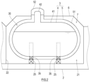
- FIG. 1 shows a ship 1 on which multiple-shell tanks 3 according to one embodiment of the present disclosure are mounted.
- the ship 1 includes a hull 2 and two multiple-shell tanks 3 mounted on the hull 2.
- the multiple-shell tanks 3 are cargo tanks for transportation of a low temperature fluid.
- the multiple-shell tanks 3 are lined up in a ship longitudinal direction. However, when the width of the ship is large, the multiple-shell tanks 3 may be lined up in a ship width direction.
- the number of multiple-shell tanks 3 mounted on the hull 2 may be one or may be three or more.
- each multiple-shell tank 3 includes: an inner shell 4 that stores cargo; and an outer shell 5 that wraps the inner shell 4.
- the inner shell 4 and the outer shell 5 are spaced apart from each other substantially uniformly.
- An inter-shell region 30 is located between the inner shell 4 and the outer shell 5 in a thickness direction of a tank wall. A heat insulation structure of the tank wall of the multiple-shell tank 3 will be described later in detail.
- the cargo may be a liquefied gas, such as a liquefied petroleum gas (LPG, about -45°C), a liquefied ethylene gas (LEG, about -100°C), a liquefied natural gas (LNG, about -160°C), liquefied oxygen (LO 2 , about -180°C), liquefied hydrogen (LH 2 , about -250°C), or liquefied helium (LHe, about -270°C).
- LPG liquefied petroleum gas
- LPG liquefied petroleum gas
- LNG liquefied natural gas
- LO 2 liquefied oxygen
- LH 2 liquefied hydrogen
- LHe liquefied helium
- the cargo does not necessarily have to be a liquid and may be a gas.
- the inner shell 4 includes an inner shell main body 41 and an inner shell dome 42.
- the inner shell main body 41 has a cylindrical shape that is long in a horizontal direction.
- the inner shell dome 42 projects upward from the inner shell main body 41.
- an axial direction of the inner shell main body 41 is parallel to the ship longitudinal direction.
- an axial direction of the inner shell dome 42 is parallel to a vertical direction.
- the axial direction of the inner shell dome 42 may be slightly inclined relative to the vertical direction.
- the outer shell 5 includes an outer shell main body 51 and an outer shell dome 52.
- the outer shell main body 51 has a cylindrical shape that is long in the horizontal direction.
- the outer shell dome 52 projects upward from the outer shell main body 51.
- the outer shell main body 51 surrounds the inner shell main body 41.
- the outer shell dome 52 surrounds the inner shell dome 42.
- an axial direction of the outer shell main body 51 is parallel to the ship longitudinal direction.
- an axial direction of the outer shell dome 52 is parallel to the vertical direction.
- each of the inner shell main body 41 and the outer shell main body 51 does not necessarily have to have a cylindrical shape that is long in the horizontal direction and may have a cylindrical shape that is long in the vertical direction.
- each of the inner shell main body 41 and the outer shell main body 51 may have a spherical shape, a cube shape, or a cuboid shape.
- the hull 2 includes two cargo holds 21 that are open upward.
- the cargo holds 21 are lined up in the ship longitudinal direction and are separated from each other by a dividing wall 22. Then, lower portions of the multiple-shell tanks 3 are inserted into the respective cargo holds 21.
- a pair of saddles 25 are located in each of the cargo holds 21.
- the saddles 25 are spaced apart from each other in the ship longitudinal direction.
- the saddles 25 support the outer shell main body 51 of the outer shell 5 of the multiple-shell tank 3.
- a pair of supports 35 are located between the inner shell 4 and the outer shell 5 of the multiple-shell tank 3.
- the supports 35 support the inner shell main body 41.
- the supports 35 are located at the same positions as the saddles 25. However, the supports 35 may be located at different positions from the saddles 25.
- Tank covers 6 are located above the respective multiple-shell tanks 3. Each of the tank covers 6 covers the corresponding multiple-shell tank 3 from above.
- a holding space 7 in which an inactive gas is filled is located between the hull 2 and the tank cover 6.
- the outer shell main body 51 of the outer shell 5 is located under the tank cover 6, and the outer shell dome 52 of the outer shell 5 penetrates the tank cover 6.
- FIG. 3 is a sectional view of the multiple-shell tank 3 according to First Example.
- the multiple-shell tank 3 includes: the inner shell 4 storing a liquefied gas; the outer shell 5 including a single shell or multiple shells and located outside the inner shell 4 with a gap so as to surround the inner shell 4; and planar thermal insulators 9 that are located so as to cover two or more surfaces among an outer surface of the inner shell 4, an inner surface of the outer shell 5, and an outer surface of the outer shell 5 and block heat radiation, heat conduction, and heat convection.
- Each of the planar thermal insulators 9 has a panel shape.
- the planar thermal insulator 9 has a thickness that is 0.01 time or more and one time or less a gap between the inner shell 4 and the outer shell 5 (first outer shell 5A) located immediately outside the inner shell 4.
- the planar thermal insulator 9 may be a multiple-layer panel in which a thermal insulator is sandwiched between plate-shaped base materials.
- the shape of the planar thermal insulator 9 is not limited to the panel shape and may be a sheet shape. Examples of such planar thermal insulator 9 include a urethane foam panel, an aerogel sheet, and sheet-shaped glass wool.
- the planar thermal insulator 9 is fixed to a surface of the inner shell 4 or a surface of the outer shell 5 by a fixture.
- a base plate 81 made of metal is joined to the inner shell 4 (or the outer shell 5) by, for example, welding.
- a stud bolt 82 is joined to the base plate 81 by a screw structure, welding, or the like.
- the material of the stud bolt 82 is not especially limited.
- GFRP glass fiber reinforced plastic
- the stud bolt 82 is inserted through a hole of the planar thermal insulator 9 and screwed into a nut 83.
- the stud bolt 82 and the nut 83 correspond to the fixture.
- the planar thermal insulator 9 may be fixed to the surface of the inner shell 4 or the surface of the outer shell 5 by an adhesive or by a self-adhesive function of urethane foam.
- the inter-shell region 30 (first inter-shell region 30A) between the inner shell 4 and the outer shell 5 (first outer shell 5A) located immediately outside the inner shell 4 is filled with a low temperature gas (such as a gas generated by evaporation of the liquefied gas as the cargo).
- the gas filled in the first inter-shell region 30A may be the gas that has been generated by the evaporation and flowed from the inner shell 4 into the first inter-shell region 30A through communication between the inner shell 4 and the first inter-shell region 30A.
- the pressure of the first inter-shell region 30A is 1 kPa or more.
- the pressure of the first inter-shell region 30A is adequately higher than that of conventional vacuum insulation.
- the pressure of the first inter-shell region 30A may be 1 kPa or more and negative pressure with respect to atmospheric pressure. In this case, the degree of vacuum of the first inter-shell region 30A is adequately lower than that of the conventional vacuum insulation.
- the first inter-shell region 30A includes a void 31 in the thickness direction of the tank wall of the multiple-shell tank 3.
- the planar thermal insulator 9 does not exist in the void 31.
- the void 31 is utilized as a space for work and has an adequate size for work.
- the void 31 may be utilized for the arrangement of pipes.
- the size of the void 31 in the thickness direction of the tank wall is, for example, 0.1 time or more and 0.99 time or less the gap of the inter-shell region 30.
- each planar thermal insulator 9 is fixed to the surface of the inner shell 4 or the surface of the outer shell 5 by the fixture, it is especially useful to include the void 31 in which the planar thermal insulators 9 are moved, and the fixtures are handled.
- the planar thermal insulator 9 and the void 31 are set to be large, the outer shell 5 becomes large, and the cost may be influenced by the increases in the installation space and the weight of the tank.
- the thickness of the planar thermal insulator 9 and the sizes of the inter-shell region 30 and the void 31 can be flexibly selected in accordance with required heat protection performance and restriction of the installation space.
- a powdered thermal insulator 95 such as pearlite, may be filled in the void 31 of the first inter-shell region 30A. With this, the heat insulation performance of the multiple-shell tank 3 can be further improved.
- the planar thermal insulators 9 include: a first planar thermal insulator located so as to cover one of an inner surface and outer surface of the first outer shell 5A located immediately outside the inner shell 4 in the outer shell 5; and a second planar thermal insulator located so as to cover the surface which is not covered with the first planar thermal insulator, among the outer surface of the inner shell 4, the inner surface of the outer shell 5, and the outer surface of the outer shell 5.
- the heat protection performance of the first planar thermal insulator and the heat protection performance of the second planar thermal insulator may be different from each other in accordance with places where the planar thermal insulators 9 are located.
- the types and thicknesses of the first planar thermal insulator and the second planar thermal insulator are suitably adjusted in accordance with the first inter-shell region 30A and a second inter-shell region 30B which are different from each other in terms of a temperature condition and an atmosphere condition. With this, even when the inter-shell region 30 is not in a high vacuum state, the multiple-shell tank 3 can obtain adequately high heat insulation performance.
- a multiple-shell tank 3A shown in FIG. 3 is a double-shell tank and includes the inner shell 4 and the outer shell 5 that is a single shell.
- the planar thermal insulator 9 is fixed to the outer surface of the inner shell 4 so as to cover the outer surface of the inner shell 4.
- the planar thermal insulator 9 is fixed to the outer surface of the outer shell 5 so as to cover the outer surface of the outer shell 5.
- a multiple-shell tank 3B shown in FIG. 6 is a double-shell tank and includes the inner shell 4 and the outer shell 5 that is a single shell.
- the planar thermal insulator 9 is fixed to the inner surface of the outer shell 5 so as to cover the inner surface of the outer shell 5.
- the planar thermal insulator 9 is fixed to the outer surface of the outer shell 5 so as to cover the outer surface of the outer shell 5.
- a multiple-shell tank 3C shown in FIG. 7 is a double-shell tank and includes the inner shell 4 and the outer shell 5 that is a single shell.
- the planar thermal insulator 9 is fixed to the inner surface of the inner shell 4 so as to cover the outer surface of the inner shell 4.
- the planar thermal insulator 9 is fixed to the inner surface of the outer shell 5 so as to cover the inner surface of the outer shell 5.
- the planar thermal insulator 9 is fixed to the outer surface of the outer shell 5 so as to cover the outer surface of the outer shell 5.
- a multiple-shell tank 3D shown in FIG. 8 is a triple-shell tank and includes the inner shell 4 and the outer shell 5 that is a double shell.
- the double outer shell 5 includes: a first outer shell 5A located immediately outside the inner shell 4; and a second outer shell 5B located outside the first outer shell 5A.
- An inactive gas (such as nitrogen) which is higher in boiling point than the gas filled in the first inter-shell region 30A is filled in the inter-shell region 30 (second inter-shell region 30B) between the first outer shell 5A and the second outer shell 5B.
- the planar thermal insulator 9 is fixed to the outer surface of the inner shell 4 so as to cover the outer surface of the inner shell 4. Moreover, the planar thermal insulator 9 is fixed to the outer surface of the first outer shell 5A so as to cover the outer surface of the first outer shell 5A. Furthermore, the planar thermal insulator 9 is fixed to the outer surface of the second outer shell 5B so as to cover the outer surface of the second outer shell 5B. In the multiple-shell tank 3D, instead of the planar thermal insulator 9 covering the outer surface of the first outer shell 5A, the planar thermal insulator 9 may be fixed to the inner surface of the first outer shell 5A so as to cover the inner surface of the first outer shell 5A.
- the planar thermal insulator 9 may be fixed to the inner surface of the second outer shell 5B so as to cover the inner surface of the second outer shell 5B.
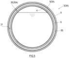
- a multiple-shell tank 3E shown in FIG. 9 is a triple-shell tank and includes the inner shell 4 and the outer shell 5 that is a double shell (the first outer shell 5A and the second outer shell 5B).
- the planar thermal insulator 9 is fixed to the inner surface of the first outer shell 5A so as to cover the inner surface of the first outer shell 5A.
- the planar thermal insulator 9 is fixed to the outer surface of the first outer shell 5A so as to cover the inner surface of the first outer shell 5A.
- At least one of the outer surface of the inner shell 4, the inner surface of the second outer shell 5B, and the outer surface of the second outer shell 5B may be covered with the planar thermal insulator 9.
- a multiple-shell tank 3F shown in FIG. 10 is a triple-shell tank and includes the inner shell 4 and the outer shell 5 that is a double shell (the first outer shell 5A and the second outer shell 5B).
- the planar thermal insulator 9 is fixed to the inner surface of the first outer shell 5A so as to cover the inner surface of the first outer shell 5A.
- the planar thermal insulator 9 is fixed to the inner surface of the second outer shell 5B so as to cover the inner surface of the second outer shell 5B.
- the planar thermal insulator 9 may be fixed to the outer surface of the first outer shell 5A so as to cover the outer surface of the first outer shell 5A.
- the planar thermal insulator 9 may be fixed to the outer surface of the second outer shell 5B so as to cover the outer surface of the second outer shell 5B.
- the planar thermal insulator 9 may be fixed to the outer surface of the inner shell 4 so as to cover the outer surface of the inner shell 4.
- the multiple-shell tank 3 of the present embodiment includes: the inner shell 4 storing the liquefied gas; the outer shell 5 including a single shell or multiple shells and located outside the inner shell 4 with a gap so as to surround the inner shell 4; and the planar thermal insulators 9 that are fixed to two or more surfaces among the outer surface of the inner shell 4, the inner surface of the outer shell 5, and the outer surface of the outer shell 5 so as to cover the two or more surfaces and block heat conduction and heat convection.
- the gas is filled in the inter-shell region 30 or the inter-shell regions 30.
- planar thermal insulators 9 when the outer shell 5 is a single shell are as below.
- the planar thermal insulators 9 are located so as to cover the outer surface of the inner shell 4 and the inner surface of the outer shell 5.
- the planar thermal insulators 9 are located so as to cover two surfaces that are the outer surface of the inner shell 4 and the outer surface of the outer shell 5.
- the planar thermal insulators 9 are located so as to cover two surfaces that are the inner surface of the outer shell 5 and the outer surface of the outer shell 5.
- the planar thermal insulators 9 are located so as to cover three surfaces that are the outer surface of the inner shell 4, the inner surface of the outer shell 5, and the outer surface of the outer shell 5.
- the ship 1 includes the hull 2 and the multiple-shell tank 3 mounted on the hull 2.
- the multiple-shell tank 3 and the ship 1 configured as above heat conduction and heat convection are blocked by two heat insulating layers that are the planar thermal insulators 9. With this, even when the inter-shell region 30 is filled with the gas, the tank wall of the multiple-shell tank 3 can obtain adequately high heat insulation performance.
- the planar thermal insulator 9 is fixed to the surface of the inner shell 4 or the surface of the outer shell 5. Therefore, even when the thermal contraction of the inner shell 4 and the outer shell 5 occurs, positional displacement or deviation of the planar thermal insulator 9 relative to the surface to which the planar thermal insulator 9 is attached hardly occurs. Therefore, the reliability of the heat insulation performance at respective portions of the tank wall can be improved.
- the pressure of the inter-shell region 30 (first inter-shell region 30A) between the inner shell 4 and the outer shell 5 (first outer shell 5A) located immediately outside the inner shell 4 may be 1 kPa or more.
- the pressure of the first inter-shell region 30A may be negative pressure with respect to atmospheric pressure.
- the tank wall of the multiple-shell tank 3 can obtain further high heat insulation performance.
- each of the planar thermal insulators 9 may have a panel shape.
- each of the planar thermal insulators 9 may be fixed by the fixture (the stud bolt 82 and the nut 83) to the surface to be covered with the planar thermal insulator 9.
- planar thermal insulator 9 Since the planar thermal insulator 9 is fixed by the fixture as above, attaching and detaching of the planar thermal insulator 9 are relatively easy, and therefore, on-site construction work can be simplified.
- each of the inter-shell regions 30 may include the void 31 for work in the thickness direction.
- the void 31 denotes a space of the inter-shell region 30 which is not occupied by the planar thermal insulator 9 and through which objects (such as workers and pipes) other than gas can pass.
- the inter-shell region 30 includes the void 31. Therefore, during construction, a worker can utilize the void 31 to perform work of attaching the planar thermal insulators 9, piping work, and the like. Moreover, during maintenance, the planar thermal insulator 9 can be inspected by introducing inspection equipment to the void 31, and a worker can perform work of, for example, replacing the planar thermal insulators 9 by utilizing the void 31.
- the planar thermal insulators 9 include: the first planar thermal insulator located so as to cover one of the inner surface and outer surface of the first outer shell 5A that is included in the outer shell 5 and is located immediately outside the inner shell 4; and the second planar thermal insulator located so as to cover the surface which is not covered with the first planar thermal insulator, among the outer surface of the inner shell 4, the inner surface of the outer shell 5, and the outer surface of the outer shell 5.
- thermal insulation is especially intensively realized inside and outside the first outer shell SA.
- the multiple-shell tank 3 is mounted on the ship 1.
- the structure of the multiple-shell tank 3 may be applied to a liquefied gas storage tank placed on land.
Landscapes
- Engineering & Computer Science (AREA)
- Mechanical Engineering (AREA)
- Chemical & Material Sciences (AREA)
- Combustion & Propulsion (AREA)
- Ocean & Marine Engineering (AREA)
- General Engineering & Computer Science (AREA)
- Physics & Mathematics (AREA)
- Thermal Sciences (AREA)
- Filling Or Discharging Of Gas Storage Vessels (AREA)
Applications Claiming Priority (1)
| Application Number | Priority Date | Filing Date | Title |
|---|---|---|---|
| PCT/JP2020/049136 WO2022144971A1 (ja) | 2020-12-28 | 2020-12-28 | 多重殻タンク及び船舶 |
Publications (2)
| Publication Number | Publication Date |
|---|---|
| EP4269225A1 true EP4269225A1 (de) | 2023-11-01 |
| EP4269225A4 EP4269225A4 (de) | 2024-09-18 |
Family
ID=82260363
Family Applications (1)
| Application Number | Title | Priority Date | Filing Date |
|---|---|---|---|
| EP20967984.4A Pending EP4269225A4 (de) | 2020-12-28 | 2020-12-28 | Mehrschaliger tank und behälter |
Country Status (5)
| Country | Link |
|---|---|
| EP (1) | EP4269225A4 (de) |
| JP (1) | JP7601908B2 (de) |
| KR (1) | KR20230119006A (de) |
| CN (1) | CN116670023A (de) |
| WO (1) | WO2022144971A1 (de) |
Families Citing this family (3)
| Publication number | Priority date | Publication date | Assignee | Title |
|---|---|---|---|---|
| KR102929675B1 (ko) * | 2023-03-16 | 2026-02-24 | 에이치디현대중공업 주식회사 | 액화가스 저장탱크 |
| EP4502451A1 (de) * | 2023-08-03 | 2025-02-05 | Crompton Technology Group Limited | Speichertank |
| KR102898530B1 (ko) * | 2023-10-24 | 2025-12-10 | 한국해양과학기술원 | 이중 단열층과 기화가스를 활용하여 단열성능이 향상된 선박용 액화수소 연료탱크 |
Family Cites Families (13)
| Publication number | Priority date | Publication date | Assignee | Title |
|---|---|---|---|---|
| JPS6372399U (de) * | 1986-10-29 | 1988-05-14 | ||
| JPH10141595A (ja) * | 1996-11-05 | 1998-05-29 | Ishikawajima Harima Heavy Ind Co Ltd | 低温液化ガス貯蔵タンク |
| KR101122549B1 (ko) * | 2009-08-26 | 2012-03-16 | 삼성중공업 주식회사 | 액화천연가스 운반선의 증발가스 억제장치 |
| NL1038506C2 (nl) * | 2011-01-10 | 2012-07-11 | Erik Jeroen Eenkhoorn | Vloeistofdichte en thermisch geã¯soleerde houder. |
| FR2996625B1 (fr) * | 2012-10-09 | 2017-08-11 | Gaztransport Et Technigaz | Reservoir etanche et isolant pour contenir un fluide froid sous pression |
| BR112015030860A2 (pt) * | 2013-06-21 | 2017-07-25 | Kawasaki Heavy Ind Ltd | tanque de estocagem de gás liquefeito e navio de transporte de gás liquefeito |
| KR20150138995A (ko) * | 2014-05-30 | 2015-12-11 | 현대중공업 주식회사 | 액화가스 처리 시스템 |
| JP6364694B2 (ja) * | 2014-07-10 | 2018-08-01 | 三菱造船株式会社 | 運搬船 |
| GB2536915B (en) * | 2015-03-31 | 2018-06-06 | Mgi Thermo Pte Ltd | Hull Insulation of a liquefied gas carrying ship having a plurality of individual tessellating insulation panels |
| GB2562994A (en) * | 2017-04-04 | 2018-12-05 | Lnt Marine Pte Ltd | Multi-layered insulation system for liquefied gas carriers |
| US11247752B2 (en) | 2017-10-16 | 2022-02-15 | Kawasaki Jukogyo Kabushiki Kaisha | Double-shell tank and ship |
| JP7273508B2 (ja) * | 2018-12-28 | 2023-05-15 | 川崎重工業株式会社 | 船舶 |
| KR102662477B1 (ko) * | 2019-04-05 | 2024-05-03 | 카와사키 주코교 카부시키 카이샤 | 액화 가스 탱크 및 액화 가스 운반선 |
-
2020
- 2020-12-28 EP EP20967984.4A patent/EP4269225A4/de active Pending
- 2020-12-28 JP JP2022572830A patent/JP7601908B2/ja active Active
- 2020-12-28 KR KR1020237024741A patent/KR20230119006A/ko not_active Ceased
- 2020-12-28 WO PCT/JP2020/049136 patent/WO2022144971A1/ja not_active Ceased
- 2020-12-28 CN CN202080108209.3A patent/CN116670023A/zh active Pending
Also Published As
| Publication number | Publication date |
|---|---|
| WO2022144971A1 (ja) | 2022-07-07 |
| EP4269225A4 (de) | 2024-09-18 |
| CN116670023A (zh) | 2023-08-29 |
| JPWO2022144971A1 (de) | 2022-07-07 |
| KR20230119006A (ko) | 2023-08-14 |
| JP7601908B2 (ja) | 2024-12-17 |
Similar Documents
| Publication | Publication Date | Title |
|---|---|---|
| EP4269225A1 (de) | Mehrschaliger tank und behälter | |
| EP3904196B1 (de) | Schiff | |
| KR102306109B1 (ko) | 단열 밀봉 탱크 | |
| EP3699476B1 (de) | Doppelmanteltank und schiff | |
| KR101616389B1 (ko) | 카고 탱크 구조 및 카고 탱크 구조 설치 방법 | |
| KR20110046627A (ko) | 독립형 액화가스 탱크의 단열 패널 결합구조 및 결합방법 | |
| CN108541247A (zh) | 用于连接独立式液化气储罐的交替堆叠的真空隔热板的结构件 | |
| KR20120035952A (ko) | 화물창 | |
| US20150008228A1 (en) | Tank container for transport and storage of cryogenic liquefied gases | |
| EP3763989B1 (de) | Flüssiggastank | |
| KR20240029773A (ko) | 낮은 압력에서 액체 수소의 저장을 위한 시스템 및 방법 | |
| KR20240058875A (ko) | 액화 가스를 위한 저장 시설 | |
| KR20240052773A (ko) | 액화 가스용 저장 설비 | |
| EP3760910B1 (de) | Doppelwandiger tank und flüssiggasträgerschiff | |
| KR20160008907A (ko) | 액화천연가스 저장탱크 | |
| KR20220036383A (ko) | 액화가스 저장탱크의 단열시스템 및 그 시공방법 | |
| KR102351594B1 (ko) | 화물창의 단열박스 및 그 제작 방법 | |
| KR101337641B1 (ko) | 단열 보드 및 이를 포함하는 액화 천연 가스 저장 탱크 | |
| KR20220137188A (ko) | 선박용 액화가스 저장탱크의 단열구조체 | |
| KR20130045500A (ko) | 액화천연가스 저장탱크의 펌프타워 단열구조 | |
| KR102469993B1 (ko) | 단열 패널용 핸들링 장치 | |
| KR20220087652A (ko) | 액화가스 저장탱크의 단열구조 및 상기 액화가스 저장탱크의 단열구조 형성방법 | |
| KR101739982B1 (ko) | 액화천연가스 저장탱크 및 액화천연가스 저장 탱크의 단열 박스 | |
| KR20200004715A (ko) | 단열 패널 | |
| KR20220136580A (ko) | 선박용 액화가스 저장탱크의 단열구조체 |
Legal Events
| Date | Code | Title | Description |
|---|---|---|---|
| STAA | Information on the status of an ep patent application or granted ep patent |
Free format text: STATUS: THE INTERNATIONAL PUBLICATION HAS BEEN MADE |
|
| PUAI | Public reference made under article 153(3) epc to a published international application that has entered the european phase |
Free format text: ORIGINAL CODE: 0009012 |
|
| STAA | Information on the status of an ep patent application or granted ep patent |
Free format text: STATUS: REQUEST FOR EXAMINATION WAS MADE |
|
| 17P | Request for examination filed |
Effective date: 20230613 |
|
| AK | Designated contracting states |
Kind code of ref document: A1 Designated state(s): AL AT BE BG CH CY CZ DE DK EE ES FI FR GB GR HR HU IE IS IT LI LT LU LV MC MK MT NL NO PL PT RO RS SE SI SK SM TR |
|
| DAV | Request for validation of the european patent (deleted) | ||
| DAX | Request for extension of the european patent (deleted) | ||
| A4 | Supplementary search report drawn up and despatched |
Effective date: 20240816 |
|
| RIC1 | Information provided on ipc code assigned before grant |
Ipc: B65D 90/06 20060101ALI20240809BHEP Ipc: B65D 90/02 20190101ALI20240809BHEP Ipc: B63B 25/08 20060101AFI20240809BHEP |