EP4269230A1 - Nouvelle architecture de pare-brise et aeronef muni d'un tel pare-brise - Google Patents
Nouvelle architecture de pare-brise et aeronef muni d'un tel pare-brise Download PDFInfo
- Publication number
- EP4269230A1 EP4269230A1 EP23170263.0A EP23170263A EP4269230A1 EP 4269230 A1 EP4269230 A1 EP 4269230A1 EP 23170263 A EP23170263 A EP 23170263A EP 4269230 A1 EP4269230 A1 EP 4269230A1
- Authority
- EP
- European Patent Office
- Prior art keywords
- aircraft
- coating layer
- fold
- coated
- peripheral edge
- Prior art date
- Legal status (The legal status is an assumption and is not a legal conclusion. Google has not performed a legal analysis and makes no representation as to the accuracy of the status listed.)
- Granted
Links
Images

Classifications
-
- B—PERFORMING OPERATIONS; TRANSPORTING
- B64—AIRCRAFT; AVIATION; COSMONAUTICS
- B64C—AEROPLANES; HELICOPTERS
- B64C1/00—Fuselages; Constructional features common to fuselages, wings, stabilising surfaces or the like
- B64C1/14—Windows; Doors; Hatch covers or access panels; Surrounding frame structures; Canopies; Windscreens accessories therefor, e.g. pressure sensors, water deflectors, hinges, seals, handles, latches, windscreen wipers
- B64C1/1476—Canopies; Windscreens or similar transparent elements
- B64C1/1492—Structure and mounting of the transparent elements in the window or windscreen
Definitions
- the present invention relates to an aircraft windshield and an aircraft provided with such a windshield.
- the invention applies to all types of aircraft equipped with a windshield and in particular to civil and military aircraft as well as helicopters.
- the windshield includes a glass comprising several plies of varied transparent materials making it possible to offer structural characteristics adapted to the necessary mechanical resistance.
- the ice must in fact resist variations in pressure and temperature, impacts of different types (birds, hail, scratches, abrasion, etc.).
- the transparent materials used can be of mineral origin (glass, quartz, silica, etc. or combination of these) or of organic origin (acrylic, polycarbonate, resins, polymethylmethacrylate more commonly called plexiglass (registered trademark), etc. . or combination thereof).
- the glasses can also include a combination of folds of organic origin and a fold of mineral origin generally of the glass positioned most outside; one of its faces is therefore in the open air.
- the windows are fixed in an opening made in the structure of the front end of the aircraft, at the level of the cockpit on a suitable frame forming part of the structure of the aircraft.
- the windows can be pinched at their peripheral edge between the frame and a clamp secured to the structure of the aircraft using screw-nut type fasteners for example or directly bolted at their peripheral edge to supervision.
- the windshield comprises a glass comprising several folds 10 of various transparent materials.
- the thicker folds are called structural folds.
- a glue 30 covers the different surfaces in contact so as to bind them together.
- the ice is fixed in an opening in the structure of the nose of the aircraft, at the level of the cockpit on a suitable frame 12.
- the glass is pinched at its peripheral edge between the frame 12 and a clamping flange 14 secured to the structure of the aircraft using screw-nut type fasteners 16.
- This type of assembly is called a flange assembly. It requires the addition of elements such as a peripheral flange making the assembly complex but possible for windows with structural folds made of material of mineral origin.
- a glass having structural folds made of material of organic origin will generally be fixed to the structure of the aircraft by a direct bolting principle, the flexibility of the materials allowing it.
- a glass having structural folds made of material of mineral origin will preferably be fixed to the structure following a flange assembly principle of the type described above in the patent mentioned allowing fixing by bolt outside the folds without them. to cross.
- the present invention aims to propose a new ice windshield architecture having at least one fold of internal mineral material making it possible to overcome all of the aforementioned drawbacks and in particular making it possible to choose the type of assembly more freely.
- the present invention relates to an aircraft windshield comprising a glass comprising at least one fold of transparent material of mineral origin and having a peripheral edge, characterized in that at least one of the folds of the glass made of mineral material is/are coated with a coating layer of viscoelastic transparent organic material over its entire surface including the peripheral edge.
- the coating of folds of mineral material in a glass with a layer of viscoelastic material allows them to be protected by reinforcing their solidity. Furthermore, the coating layer is used to improve the seal and facilitate the assembly of the windshield on the aircraft structure by allowing, for example, fixing by direct bolting despite the use of layers of mineral material.
- the invention provides at least one of the following optional characteristics, taken individually or in combination.
- Each of the layers of mineral material in the ice is coated.
- An outer ply of uncoated mineral material is provided, the outer face of which is the outermost face of the ice and the inner face is adjoined to the outer face of the outermost coating layer by the via a glue and in that each of the internal folds is coated.
- the coating layer forms a one-piece envelope.
- the coating layer is made of Opticor material (registered trademark).
- the coating layer includes an extension at the entire peripheral edge of the ply which has a through opening.
- the mineral material is glass.
- the present invention also relates to an aircraft comprising a frame forming part of the primary structure of the aircraft and a windshield associated with said frame having one or more of the aforementioned characteristics.
- the coated fold(s) and the coating layer are held using a flange fixing.
- screw-nut type fixing means pass through the extension through the opening to enclose the coating layer and the coated fold(s).
- FIG 2 represents an aircraft 32 comprising a front end 34 in which a cockpit is located.
- the front tip 34 includes a windshield 36 provided with at least one glass 38.
- at least one window 38 of the aircraft windshield 36 comprises at least one ply 40 of transparent material of mineral origin.
- the fold(s) 40 have a peripheral edge 42.
- the fold(s) 40 have an exterior face 40a facing the outside of the aircraft as opposed to the interior face 40b facing the cockpit.
- exterior/interior will be used in the remainder of the description to indicate for the exterior term a greater proximity to the exterior of the aircraft and interior to the interior of the aircraft, i.e. in the example illustrated, the position piloting.
- the glass 38 comprises a fold 40 of transparent mineral material and in the example illustrated of glass.
- the glass 38 is fixed to the primary structure of the aircraft 32 and more precisely to a part called the frame 44 which is part of it by a fixing system explained below.
- the frame 44 encircles the mirror 38.
- At least one fold 40 of the glass 38 made of transparent mineral material is(are) coated with a layer 46 called coating of viscoelastic transparent organic material over the entirety of its/their surface including the/their edge 42 peripheral.
- the coating layer 46 completely envelops the fold 40.
- the coating layer 46 has an exterior face 46a closest to the exterior environment of the aircraft and an opposite interior face 46b.
- the transparent viscoelastic organic material could for example be Opticor (registered trademark).
- the whole is obtained by molding in a mold designed so that the whole adapts perfectly to the frame.
- glue 47 is used to adhere the plies to each other as illustrated in the figures 5 and 6 .
- the glue is a polyvintethane glue, called PVB glue.
- the glue 47 can also be applied to the entire surface of the fold, namely the faces 40a and 40b as well as to the peripheral edge 42 in order to improve overall cohesion.
- the coating layer 46 includes an extension, called extension 48, at the peripheral edge 42 of the fold over its entire circumference.
- the coating layer 46 has a thickness e2 ( Figure 4 ), e"2 ( Figure 6 ) more important at the level of the peripheral edge 42 of the fold to constitute this extension 48.
- the extension 48 has through orifices 49 distributed over the entire circumference of the fold and according to a possible shape, regularly distributed at least over the majority of the extension .
- only one internal fold 40 is provided for the sake of simplification in the description but several coated folds could be provided. Identical elements retain the same references from one embodiment to another.
- the thickness of the coating layer is uniform over the entire surface of each face 40a, 40b of the fold 40 but differs from one face 40a (thickness e1) to the other 40b (thickness e3).
- the thickness e1 at its exterior face 40a is greater than the thickness e3 at its interior face 40b so as to allow the integration of a retaining device 52.
- the retaining device 52 comprising an outer plate 54 and an inner plate 56, made for example of metal and for illustration purposes of aluminum, makes it possible to sandwich the peripheral edge 53 of the coating layer 46 with the peripheral edge 42 of the fold 40.
- the coating layer 46 is hollowed out at the level of the edge 53 peripheral of its external face 46a.
- the formed cavity 58 open to the outside makes it possible to receive on the coating layer 46 the outer plate 54 of the retaining device 52 in such a way that its outer face 54a is flush with the outer face 46a of the coating layer.
- the space between the outer plate 54 of the retaining device and the coating layer 46 is filled by a seal 60.
- the extension has a thickness h equal to the sum of the thickness of the fold h1 and the thickness of the coating layer e1 and e3 on both sides of the fold 40, reduced by the thickness h2 of the cavity 58 and the seal 60.
- the outer plate 54 is intended to be attached to the outer face 46a of the coating layer and the inner plate 56 to the inner face 46b of the coating layer.
- the assembly of the retaining device 52, the seal 60, the coating layer 46 and the ply is clamped and fixed together using a bolt 50 (screw-nut type).
- a spacer 62 makes it possible to keep the plates 54, 56 of the retaining device 52 at a distance, the seal 58 filling the free space as seen previously.
- the outer plate 54 of the retaining device is of length such that it protrudes from the peripheral edge 53 outside the coating layer to rest on the frame 44.
- Another through opening 64 is provided in the outer plate 54 for means 66 for fixing by bolting between the plate 54 and the frame 44 for fixing the plate on the frame.
- FIG. 6 presents another embodiment of connection by direct bolting. Identical elements are found and retain the same reference such as the retaining device 52 composed of an outer plate 54 and an inner plate 56 and the spacer 62.
- the difference with the embodiment of the figure 4 consists of the presence of an outer ply 68 not coated in mineral material and the fact of enclosing the inner ply with the coating layer and fixing the glass to the frame by the same fixing means.
- the thickness e"1, e"3 of the coating layer is uniform over the entire surface of each face 40a, 40b of the fold and different from one face to the other, namely that the thickness e" 1 is different from the thickness e"3. They could be of identical thickness.
- the thickness h" of the extension corresponds to the sum of the thickness of the fold h"1 and the thickness e"1, e"3 of the coating layer of the two sides of the fold. In this way it emerges a continuity of thickness of the ice formed by the coated ply at the level of the extension 48.
- the outer ply 68 is fixed to the coating layer of the inner ply 40 using the glue 47 described above.
- the outer fold 68 has a dimension smaller than the inner fold 40 in both longitudinal and lateral directions. It is protected by a seal 70 all along its peripheral edge 71; the seal 70 is provided on the exterior face 46a of the coating layer; it is fixed between the outer plate 54 and the outer fold 68 to ensure sealing.
- a seal 72 is also provided at the level of the inner peripheral edge 73 of the inner plate 56 of the retaining device 52 to prevent water from infiltrating inside the aircraft and avoid pressure losses at the cockpit level.
- the joints 70 and 72 are in one piece. They can be made of silicone.
- the inner 56 and outer 54 plates of the retaining device, the extension 48 and the frame 44 have aligned through holes 49: the assembly is held using a bolt 50 adapted to port 49.
- the ice includes two plies, an inner ply 40 and an outer ply 68. Only the inner ply 40 is coated.
- the outer ply 68 is composed of a mineral material (as in the example of the Figure 6 ).
- the outer fold 68 has a dimension smaller than the inner fold 40 in both longitudinal and lateral directions. It is protected by a seal 70 all along its peripheral edge 71 and retained on the inner fold 40 coated by the glue 47 provided on its interior side.
- the peripheral edge 42 of the coated inner ply 40 is surrounded by a seal 82.
- the joints 70 and 82 are in one piece. They can be made of silicone.
- the peripheral edge 53 of the glass and more precisely the seal 82 is sandwiched, interposed between the frame 44 and a flange 84 whose shape matches that of the frame 44: the shape of the flange 84 also matches the shape of the peripheral edge 53 of the glass surrounded by the seal 82.
- the flange 84 in the example illustrated is fixed on the frame 44 by means of a bolt 86 penetrating into a through hole 88 of the flange and a through hole 90 of the frame 44 aligned so as to block the peripheral edge of the glass between the flange and the frame. The frame and the flange are held together and tightened against each other using bolt 86.
- the frame 44 and the flange 84 forms a clamp in which the inner fold 40 is held, coated by its peripheral edge 42.
- the seals 70 and 82 completely envelop the peripheral edge of the glass so that it is not in direct contact with the frame 44 and the flange 84.
- the flange 84 is made for example of metal, by known machining means.
- the seal 82 encircling the peripheral edge 42 of the window is compressed so as to ensure sealing between the interior and exterior of the aircraft on the entire perimeter of the ice. Additional seals can be provided to reinforce or complete this seal.
- the dimension of the outer fold 68 is such that the fold enveloped in the seal 70 fits into the opening offered by the flange 84.
- the other inner fold 40 projects towards the structure of the aircraft with respect to the outer fold 68.
- the outer fold 68 held by the seal adjoins the free end of the flange 84.
- any other form of fixing the ice comprising one or more folds of coated mineral material to the primary structure is possible.
- the examples provided are only given as an illustration of application to folded ice made of coated mineral material.
Landscapes
- Engineering & Computer Science (AREA)
- Mechanical Engineering (AREA)
- Aviation & Aerospace Engineering (AREA)
- Securing Of Glass Panes Or The Like (AREA)
- Laminated Bodies (AREA)
- Surface Treatment Of Glass (AREA)
Abstract
Description
- La présente invention concerne un pare-brise d'aéronef et un aéronef pourvu d'un tel pare-brise. L'invention s'applique à tous les types d'aéronefs munis d'un pare-brise et notamment aux avions civils et militaires ainsi qu'aux hélicoptères.
- Dans la plupart des aéronefs, le pare-brise comprend une glace comprenant plusieurs plis de matériaux transparents variés permettant d'offrir des caractéristiques structurales adaptées à la résistance mécanique nécessaire. Les glaces doivent en effet résister aux variations de pression et de température, aux impacts de différentes natures (oiseaux, grêle, rayures, abrasion ...). Les matériaux transparents utilisés peuvent être d'origine minérale (verre, quartz, silice ... ou combinaison de ceux-ci) ou d'origine organique (acrylique, polycarbonate, résines, polymethylmethacrylate appelé plus communément plexiglas (marque déposée), ... ou combinaison de ceux-ci). Les glaces peuvent également comprendre une combinaison de plis d'origine organique et d'un pli d'origine minérale en général du verre positionné le plus à l'extérieur ; l'une de ses faces est donc à l'air libre. Les glaces sont fixées dans une ouverture ménagée dans la structure de la pointe avant de l'aéronef, au niveau du poste de pilotage sur un encadrement adapté faisant partie de la structure de l'aéronef. Les glaces peuvent être pincées au niveau de leur rebord périphérique entre l'encadrement et une bride de serrage assujetties à la structure de l'aéronef à l'aide de fixations de type vis-écrou par exemple ou directement boulonnées au niveau de leur rebord périphérique à l'encadrement.
- Selon l'exemple décrit dans le
brevet FR2830236 figure 1 , le pare-brise comprend une glace comprenant plusieurs plis 10 de matériaux transparents variés. Les plis les plus épais sont appelés plis structuraux. Une colle 30 recouvre les différentes surfaces en contact de manière à les lier entre elles. La glace est fixée dans une ouverture ménagée dans la structure de la pointe avant de l'aéronef, au niveau du poste de pilotage sur un encadrement 12 adapté. La glace est pincée au niveau de son rebord périphérique entre l'encadrement 12 et une bride de serrage 14 assujettie à la structure de l'aéronef à l'aide de fixations de type vis-écrou 16. Ce type d'assemblage est dénommé un assemblage par bride. Il requiert l'adjonction d'éléments tels qu'une bride en périphérie rendant l'assemblage complexe mais possible pour des glaces à plis structuraux en matériau d'origine minérale. - Les diverses contraintes auxquelles sont soumis les pare-brise impliquent l'utilisation de matériaux déterminés parmi ceux précités. Ainsi une glace présentant des plis structuraux en matériau d'origine organique sera de manière générale fixée à la structure de l'aéronef par un principe de boulonnage direct, la souplesse des matériaux le permettant. Une glace présentant des plis structuraux en matériau d'origine minérale sera de préférence fixée à la structure suivant un principe d'assemblage par bride du type de celui décrit ci-dessus dans le brevet mentionné permettant la fixation par boulon en dehors des plis sans les traverser.
- La présente invention vise à proposer une nouvelle architecture de pare-brise à glace présentant au moins un pli en matériau minéral interne permettant de pallier tous les inconvénients précités et permettant notamment de choisir plus librement le type d'assemblage.
- A cet effet, la présente invention concerne un pare-brise d'aéronef comprenant une glace comportant au moins un pli de matériau transparent et d'origine minéral et présentant un bord périphérique, caractérisé en ce qu'au moins un des plis de la glace en matériau minéral est/sont enrobé(s) d'une couche d'enrobage de matériau organique transparent viscoélastique sur l'ensemble de sa/leur surface incluant le bord périphérique.
- L'enrobage de plis en matériau minéral d'une glace par une couche de matière viscoélastique permet de les protéger en renforçant leur solidité. Par ailleurs la couche d'enrobage est utilisée pour améliorer l'étanchéité et faciliter l'assemblage du pare-brise sur la structure avion en permettant par exemple une fixation par boulonnage direct malgré l'utilisation de plis en matériau minéral.
- L'invention prévoit au moins l'une des caractéristiques optionnelles suivantes, prises isolément ou en combinaison.
- Chacun des plis en matériau minéral de la glace est enrobé.
- Un pli externe en matériau minéral non enrobé est prévu dont la face extérieure est la face la plus à l'extérieur de la glace et la face interne est accolée à la face extérieure de la couche d'enrobage la plus à l'extérieur par l'intermédiaire d'une colle et en ce que chacun des plis interne est enrobé.
- La couche d'enrobage forme une enveloppe monobloc.
- La couche d'enrobage est en matériau Opticor (marque déposée).
- La couche d'enrobage comprend une extension au niveau de la totalité du bord périphérique du pli qui présente une ouverture traversante.
- Le matériau minéral est du verre.
- La présente invention concerne également un aéronef comprenant un encadrement faisant partie de la structure primaire de l'aéronef et un pare-brise associé audit encadrement présentant une ou plusieurs des caractéristiques précitées.
- Selon une première forme de réalisation, le ou les plis enrobés et la couche d'enrobage sont maintenus à l'aide d'une fixation par bride.
- Selon une deuxième forme de réalisation, des moyens de fixation de type vis-écrou traversent l'extension par l'ouverture pour enserrer la couche d'enrobage et le ou les plis enrobés.
- D'autres buts, caractéristiques et avantages ressortiront de la description de l'invention qui va suivre, description donnée à titre d'exemple uniquement non limitatif, en référence aux dessins ci-annexés dans lesquels :
- [
Fig. 1 ] est une vue en en plan en coupe transversal d'un pare-brise selon l'art antérieur ; - [
Fig. 2 ] est une vue en perspective d'un aéronef muni d'un pare-brise selon la présente invention ; - [
Fig. 3 ] est une vue en perspective éclatée d'une glace d'un pare-brise et d'un encadrement d'aéronef selon la présente invention ; - [
Fig. 4 ] est une vue en plan en coupe transversale selon un plan tel que le plan X-X représenté sur lafigure 3 d'une première forme de réalisation d'un pare-brise selon la présente invention ; - [
Fig. 5 ] est une vue en plan en coupe transversale selon un plan tel que le plan X-X représenté sur lafigure 3 d'une deuxième forme de réalisation d'un pare-brise selon la présente invention ; - [
Fig. 6 ] est une vue en plan en coupe transversale selon un plan tel que le plan X-X représenté sur lafigure 3 d'une troisième forme de réalisation d'un pare-brise selon la présente invention. - La
figure 2 représente un aéronef 32 comportant une pointe avant 34 dans laquelle se trouve un poste de pilotage. La pointe avant 34 comprend un pare-brise 36 muni d'au moins une glace 38. Comme montré sur lesfigures 4 à 6 , au moins une glace 38 du pare-brise 36 d'aéronef comprend au moins un pli 40 de matériau transparent d'origine minéral. Le ou les plis 40 présentent un bord 42 périphérique. Le ou les plis 40 présentent une face extérieure 40a tournée vers l'extérieur de l'aéronef par opposition à la face intérieure 40b tournée vers le poste de pilotage. Les termes extérieur/intérieur seront utilisés dans la suite de la description pour indiquer pour le terme extérieur une plus grande proximité avec l'extérieur de l'aéronef et intérieur avec l'intérieur de l'aéronef soit dans l'exemple illustré, le poste de pilotage. Dans l'exemple illustré (figures 3 à 6 ), la glace 38 comprend un pli 40 en matériau minéral transparent et dans l'exemple illustré en verre. La glace 38 est fixée à la structure primaire de l'aéronef 32 et plus précisément à une partie appelée encadrement 44 qui en fait partie par un système de fixation explicité plus loin. L'encadrement 44 encercle la glace 38. - Selon la présente invention, comme montré dans l'ensemble des formes de réalisation données uniquement à titre illustratif sur les
figures 4 à 6 , au moins un pli 40 de la glace 38 en matériau minéral transparent est(sont) enrobé(s) d'une couche 46 dite d'enrobage de matériau organique transparent viscoélastique sur l'ensemble de sa/leur surface incluant le/leur bord 42 périphérique. La couche 46 d'enrobage enveloppe complètement le pli 40. La couche 46 d'enrobage présente une face 46a extérieure la plus proche de l'environnement extérieur de l'aéronef et une face opposée intérieure 46b. De ce fait, le pli 40 en matériau minéral, ici en verre, se trouve entièrement protégé et sa solidité s'en trouve renforcée et durée de vie prolongée. La couche 46 d'enrobage de matériau organique viscoélastique transparent forme une enveloppe protectrice monobloc. Le matériau organique viscoélastique transparent pourrait être par exemple de l'Opticor (marque déposée). L'ensemble est obtenu par moulage dans un moule conçu pour que l'ensemble s'adapte parfaitement à l'encadrement. Lorsque plusieurs plis enrobés se superposent pour former la glace, une colle 47 est utilisée pour l'adhésion des plis les uns aux autres comme illustré sur lesfigures 5 et 6 . A titre illustratif, la colle est une colle polyvintéthane, appelée colle PVB. Selon une forme particulière de l'invention, la colle 47 peut également être appliquée sur l'ensemble de la surface du pli à savoir les faces 40a et 40b ainsi que sur le bord 42 périphérique afin d'améliorer la cohésion d'ensemble. - Lorsqu'un assemblage par boulonnage direct est utilisé pour fixer la glace 38 à l'encadrement 44 comme sur les
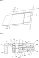
figures 4 et6 , la couche 46 d'enrobage comporte un prolongement, appelée extension 48, au niveau du bord 42 périphérique du pli sur toute sa circonférence. La couche d'enrobage 46 présente une épaisseur e2 (figure 4 ), e"2 (figure 6 ) plus importante au niveau du bord périphérique 42 du pli pour constituer cette extension 48. L'extension 48 présente des orifices 49 traversant répartis sur toute la circonférence du pli et selon une forme possible, régulièrement répartis au moins sur la majorité de l'extension. Comme indiqué plus haut, dans toutes les formes de réalisation décrites ci-dessous, seul un pli interne 40 est prévu par souci de simplification dans la description mais plusieurs plis enrobés pourraient être prévus. Des éléments identiques conservent les mêmes références d'une forme de réalisation à l'autre. - Dans l'exemple de la
figure 4 , l'épaisseur de la couche d'enrobage est uniforme sur toute la surface de chaque face 40a, 40b du pli 40 mais diffère d'une face 40a (épaisseur e1) à l'autre 40b (épaisseur e3). L'épaisseur e1 au niveau de sa face extérieure 40a est supérieure à l'épaisseur e3 au niveau de sa face intérieure 40b de manière à permettre l'intégration d'un dispositif 52 de retenue. Le dispositif de retenue 52 comprenant une plaque extérieure 54 et une plaque intérieure 56, fait par exemple de métal et à titre illustratif en aluminium, permet de maintenir en sandwich le bord 53 périphérique de la couche d'enrobage 46 avec le bord 42 périphérique du pli 40. La couche d'enrobage 46 est évidée au niveau du bord 53 périphérique de sa face externe 46a. La cavité formée 58 ouverte sur l'extérieur permet de recevoir sur la couche d'enrobage 46 la plaque extérieure 54 du dispositif de retenue 52 de manière telle que sa face extérieure 54a affleure la face extérieure 46a de la couche d'enrobage. L'espace entre la plaque extérieure 54 du dispositif de retenue et la couche d'enrobage 46 est comblé par un joint 60 d'étanchéité. Au niveau de l'orifice traversant 49, l'extension présente une épaisseur h égale à la somme de l'épaisseur du pli h1 et de l'épaisseur de la couche d'enrobage e1 et e3 des deux côtés du pli 40, diminuée de l'épaisseur h2 de la cavité 58 et du joint 60. La plaque extérieure 54 est destinée à être accolée sur la face 46a extérieure de la couche d'enrobage et la plaque intérieure 56 sur la face 46b intérieure de la couche d'enrobage. L'ensemble du dispositif de retenue 52, du joint 60, de la couche d'enrobage 46 et du pli est enserré et fixé ensemble à l'aide d'un boulon 50 (de type vis-écrou). Une entretoise 62 permet de maintenir à distance les plaques 54, 56 du dispositif de retenue 52, le joint 58 comblant l'espace libre comme vu précédemment. La plaque extérieure 54 du dispositif de retenue est de longueur telle qu'elle dépasse du bord périphérique 53 à l'extérieur de la couche d'enrobage pour venir reposer sur l'encadrement 44. Une autre ouverture 64 traversante est prévue dans la plaque extérieure 54 pour des moyens 66 de fixation par boulonnage entre la plaque 54 et l'encadrement 44 pour la fixation de la plaque sur l'encadrement. - La
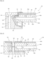
figure 6 présente une autre forme de réalisation de jonction par boulonnage direct. Des éléments identiques se retrouvent et conservent la même référence comme le dispositif de retenue 52 composé d'une plaque extérieure 54 et d'une plaque intérieure 56 et l'entretoise 62. La différence avec la forme de réalisation de lafigure 4 consiste en la présence d'un pli extérieur 68 non enrobé en matériau minéral et le fait d'enserrer le pli intérieur avec la couche d'enrobage et de fixer la glace à l'encadrement par des mêmes moyens de fixation. Dans l'exemple de lafigure 6 , l'épaisseur e"1, e"3 de la couche d'enrobage est uniforme sur toute la surface de chaque face 40a, 40b du pli et différente d'une face à l'autre, à savoir que l'épaisseur e"1 est différente de l'épaisseur e"3. Elles pourraient être d'épaisseur identique. Au niveau de l'ouverture traversante 49, l'épaisseur h" de l'extension correspond à la somme de l'épaisseur du pli h"1 et de l'épaisseur e"1, e"3 de la couche d'enrobage des deux côtés du pli. De cette manière il en ressort une continuité d'épaisseur de la glace formée par le pli enrobé au niveau de l'extension 48. Le pli extérieur 68 est fixé à la couche d'enrobage du pli 40 intérieur à l'aide de la colle 47 décrite plus haut. Le pli extérieur 68 présente dans les deux directions longitudinale et latérale une dimension inférieure au pli intérieur 40. Il est protégé par un joint 70 tout le long de son bord périphérique 71 ; le joint 70 est prévu sur la face extérieure 46a de la couche d'enrobage ; il est fixé entre la plaque extérieure 54 et le pli 68 extérieur pour assurer l'étanchéité. Un joint 72 d'étanchéité est également prévu au niveau du bord périphérique intérieur 73 de la plaque intérieure 56 du dispositif 52 de retenue pour empêcher l'eau de s'infiltrer à l'intérieur de l'aéronef et éviter des pertes de pression au niveau du poste de pilotage. Dans la forme de réalisation illustrée, les joints 70 et 72 sont monobloc. Ils peuvent être réalisés en silicone. Dans cette forme de réalisation, les plaques intérieure 56 et extérieure 54 du dispositif de retenue, l'extension 48 et l'encadrement 44 présentent des orifices traversant 49 alignés : l'ensemble est maintenu à l'aide d'un boulon 50 adapté à l'orifice 49. - Selon une autre forme de réalisation de fixation par bride représentée sur la
figure 5 , la glace comprend deux plis, un pli intérieur 40 et un pli extérieur 68. Seul le pli 40 intérieur est enrobé. Le pli extérieur 68 est composé d'un matériau minéral (comme dans l'exemple de lafigure 6 ). Le pli extérieur 68 présente dans les deux directions longitudinale et latérale une dimension inférieure au pli intérieur 40. Il est protégé par un joint 70 tout le long de son bord périphérique 71 et retenu sur le pli intérieur 40 enrobé par la colle 47 prévue sur sa face intérieure. Le bord périphérique 42 du pli intérieur 40 enrobé est entouré par un joint 82 d'étanchéité. Dans la forme de réalisation illustrée, les joints 70 et 82 sont monobloc. Ils peuvent être réalisés en silicone. Le bord périphérique 53 de la glace et plus précisément le joint 82 est pris en sandwich, intercalé entre l'encadrement 44 et une bride 84 dont la forme épouse celle de l'encadrement 44 : la forme de la bride 84 épouse également la forme du bord périphérique 53 de la glace entouré par le joint 82. La bride 84 dans l'exemple illustré est fixée sur l'encadrement 44 au moyen d'un boulon 86 pénétrant dans un orifice traversant 88 de la bride et un orifice traversant 90 de l'encadrement 44 aligné de manière à bloquer le bord périphérique de la glace entre la bride et l'encadrement. L'encadrement et la bride sont maintenus ensemble et serrés l'un contre l'autre à l'aide du boulon 86. L'encadrement 44 et la bride 84 forment une pince dans laquelle se trouve maintenu le pli intérieur 40 enrobé par son bord périphérique 42. Les joints 70 et 82 enveloppent complètement le bord périphérique de la glace de manière qu'elle ne soit pas en contact direct avec l'encadrement 44 et la bride 84. La bride 84 est réalisée par exemple en métal, par des moyens connus d'usinage. Lorsque la bride 84 est serrée sur l'encadrement 44 par le boulon 86, le joint 82 encerclant le bord périphérique 42 de la glace est comprimé de telle sorte à assurer l'étanchéité entre l'intérieur et l'extérieur de l'aéronef sur la totalité du pourtour de la glace. Des joints additionnels peuvent être prévus pour renforcer ou compléter cette étanchéité. La dimension du pli extérieur 68 est telle que le pli enveloppé dans le joint 70 s'imbrique dans l'ouverture offerte par la bride 84. L'autre pli intérieur 40 déborde vers la structure de l'aéronef par rapport au pli extérieur 68. Le pli extérieur 68 maintenu par le joint jouxte l'extrémité libre de la bride 84. - Toute autre forme de fixation de la glace comprenant un ou plusieurs plis en matériau minéral enrobé, à la structure primaire est possible. Les exemples apportés ne sont donnés qu'à titre illustratif d'application à la glace à pli en matériau minéral enrobé.
Claims (10)
- Pare-brise d'aéronef comprenant une glace (38) comportant au moins un pli (40) de matériau transparent et d'origine minéral et présentant un bord périphérique (42), caractérisé en ce qu'au moins un des plis (40) de la glace en matériau minéral est/sont enrobé(s) d'une couche (46) d'enrobage de matériau organique transparent viscoélastique sur l'ensemble de sa/leur surface incluant le bord périphérique (42).
- Pare-brise d'aéronef selon la revendication 1, caractérisé en ce que chacun des plis en matériau minéral de la glace est enrobé.
- Pare-brise d'aéronef selon la revendication 1, caractérisé en ce que un pli externe (68) en matériau minéral non enrobé est prévu dont la face extérieure est la face la plus à l'extérieur de la glace et la face interne est accolée à la face (46a) extérieure de la couche (46) d'enrobage la plus à l'extérieur par l'intermédiaire d'une colle (47) et en ce que chacun des plis interne (40) est enrobé.
- Pare-brise d'aéronef selon l'une des revendications 1 à 3, caractérisé en ce que la couche (46) d'enrobage forme une enveloppe monobloc.
- Pare-brise d'aéronef selon l'une des revendications 1 à 4, caractérisé en ce que la couche d'enrobage est en matériau Opticor (marque déposée).
- Pare-brise d'aéronef selon l'une des revendications 1 à 5, caractérisé en ce que la couche (46) d'enrobage comprend une extension (48) au niveau de la totalité du bord (42) périphérique du pli qui présente une ouverture (49) traversante.
- Pare-brise d'aéronef selon l'une des revendications 1 à 6, caractérisé en ce que le matériau minéral est du verre.
- Aéronef comprenant un encadrement (44) faisant partie de la structure primaire de l'aéronef et un pare-brise (36) associé audit encadrement (44) selon l'une des revendications 1 à 7.
- Aéronef selon la revendication 8, caractérisé en ce que le ou les plis (40) enrobés et la couche d'enrobage (46) sont maintenues à l'aide d'une fixation par bride (84).
- Aéronef selon les revendications 6 et 8, caractérisé en ce que des moyens de fixation de type vis-écrou (50) traversent l'extension par l'ouverture (49) pour enserrer la couche d'enrobage (46) et le ou les plis (40) enrobés.
Applications Claiming Priority (1)
| Application Number | Priority Date | Filing Date | Title |
|---|---|---|---|
| FR2204031A FR3135060A1 (fr) | 2022-04-28 | 2022-04-28 | Nouvelle architecture de pare-brise et aeronef muni d’un tel pare-brise |
Publications (2)
| Publication Number | Publication Date |
|---|---|
| EP4269230A1 true EP4269230A1 (fr) | 2023-11-01 |
| EP4269230B1 EP4269230B1 (fr) | 2025-01-01 |
Family
ID=83506178
Family Applications (1)
| Application Number | Title | Priority Date | Filing Date |
|---|---|---|---|
| EP23170263.0A Active EP4269230B1 (fr) | 2022-04-28 | 2023-04-27 | Nouvelle architecture de pare-brise et aeronef muni d'un tel pare-brise |
Country Status (4)
| Country | Link |
|---|---|
| US (1) | US12319399B2 (fr) |
| EP (1) | EP4269230B1 (fr) |
| CN (1) | CN116968915A (fr) |
| FR (1) | FR3135060A1 (fr) |
Citations (3)
| Publication number | Priority date | Publication date | Assignee | Title |
|---|---|---|---|---|
| FR2830236A1 (fr) | 2001-10-02 | 2003-04-04 | Airbus France | Dispositif de fixation d'un pare-brise d'aeronef |
| US8033505B2 (en) * | 2007-04-18 | 2011-10-11 | Airbus Deutschland Gmbh | Aircraft door window |
| US20200298952A1 (en) * | 2019-03-22 | 2020-09-24 | Bombardier Inc. | Optically enhanced aircraft window |
Family Cites Families (8)
| Publication number | Priority date | Publication date | Assignee | Title |
|---|---|---|---|---|
| US2293656A (en) * | 1942-01-03 | 1942-08-18 | Lockheed Aircraft Corp | Transparent closure and mounting |
| US2808355A (en) * | 1956-06-11 | 1957-10-01 | North American Aviation Inc | Glass enclosure |
| GB1060031A (en) * | 1965-01-06 | 1967-02-22 | British Aircraft Corp Ltd | Improvements in mountings for aircraft windscreens |
| US20090280329A1 (en) * | 2004-09-01 | 2009-11-12 | Ppg Industries Ohio, Inc. | Polyurethanes, Articles and Coatings Prepared Therefrom and Methods of Making the Same |
| WO2015069339A2 (fr) * | 2013-08-06 | 2015-05-14 | Ppg Industries Ohio, Inc. | Hublot d'avion déformable |
| US9986669B2 (en) * | 2015-11-25 | 2018-05-29 | Ppg Industries Ohio, Inc. | Transparency including conductive mesh including a closed shape having at least one curved side |
| US11337311B2 (en) * | 2018-07-06 | 2022-05-17 | Ppg Industries Ohio, Inc. | Aircraft window with variable power density heater film |
| FR3103411B1 (fr) * | 2019-11-21 | 2021-11-26 | Saint Gobain | Vitrage feuilleté pour véhicule aérien léger, chauffant sur une partie de sa surface |
-
2022
- 2022-04-28 FR FR2204031A patent/FR3135060A1/fr not_active Ceased
-
2023
- 2023-04-26 US US18/307,243 patent/US12319399B2/en active Active
- 2023-04-27 CN CN202310473429.1A patent/CN116968915A/zh active Pending
- 2023-04-27 EP EP23170263.0A patent/EP4269230B1/fr active Active
Patent Citations (3)
| Publication number | Priority date | Publication date | Assignee | Title |
|---|---|---|---|---|
| FR2830236A1 (fr) | 2001-10-02 | 2003-04-04 | Airbus France | Dispositif de fixation d'un pare-brise d'aeronef |
| US8033505B2 (en) * | 2007-04-18 | 2011-10-11 | Airbus Deutschland Gmbh | Aircraft door window |
| US20200298952A1 (en) * | 2019-03-22 | 2020-09-24 | Bombardier Inc. | Optically enhanced aircraft window |
Also Published As
| Publication number | Publication date |
|---|---|
| US12319399B2 (en) | 2025-06-03 |
| EP4269230B1 (fr) | 2025-01-01 |
| CN116968915A (zh) | 2023-10-31 |
| FR3135060A1 (fr) | 2023-11-03 |
| US20230348037A1 (en) | 2023-11-02 |
Similar Documents
| Publication | Publication Date | Title |
|---|---|---|
| EP2106364B1 (fr) | Section de fuselage pour aeronef et aeronef comprenant une telle section | |
| EP1824696B1 (fr) | Vitrage complexe constitue d'au moins deux elements vitres contigus et procede de realisation de ce vitrage complexe. | |
| EP0962741B1 (fr) | Dispositif de liaison provisoire et de séparation pyrotechinique de deux emsembles non metalliques | |
| FR2917042A1 (fr) | Cabine de conduite de train comprenant une verriere. | |
| FR2939104A1 (fr) | Aeronef a glaces de pare-brise internchangeables entre differents types | |
| CA3057601A1 (fr) | Vitrage comprenant au moins un cordon profile pour la liaison entre deux vitres et vitre pour un tel vitrage | |
| FR3089947A1 (fr) | élément de fuselage transparent d’un aéronef destiné à obturer une baie dudit aéronef | |
| EP2121362B1 (fr) | Procede d'assemblage par collage d'un vitrage sur son support et moyens pour la mise en oeuvre de ce procede | |
| EP0893340B1 (fr) | Kit pour le montage d'un vitrage feuilleté coulissant dans un cockpit d'avion | |
| EP4269230B1 (fr) | Nouvelle architecture de pare-brise et aeronef muni d'un tel pare-brise | |
| CA3057604A1 (fr) | Vitrage comprenant un seul cordon profile pour la liaison entre deux vitres et vitre pour un tel vitrage | |
| FR2684051A1 (fr) | Dispositif d'etancheite pour panneaux transparents affleurant sur une carrosserie de vehicule. | |
| WO2019115931A1 (fr) | Vitrage, notamment pour l'aéronautique, apte a être bloque dans son ouverture d'accueil en cas de rupture | |
| EP4476134B1 (fr) | Ensemble vitré pour un aéronef, procédé de fabrication d'un tel ensemble vitré, et aéronef comprenant un tel ensemble vitré | |
| EP3476717B1 (fr) | Pare-brise d'aéronef avec une glace à bride intégrée et entretoises de transfert et répartition des charges | |
| EP0962742B1 (fr) | Dispositif de découpe de pièces non metalliques au moyen d'un tube à expansion pyrotechnique | |
| EP4313579B1 (fr) | Vitrage comportant deux vitres et un joint d'assemblage desdites vitres | |
| WO2006077296A1 (fr) | Pare brise panoramique pour vehicule automobile | |
| WO2024056879A1 (fr) | Système vitré configuré pour bloquer des rotations de vitrage | |
| EP4719895A1 (fr) | Vitrage clampé et ensemble vitrage le comprenant | |
| WO2024056878A1 (fr) | Système vitré configuré pour bloquer des glissements de vitrage | |
| FR3113093A1 (fr) | Systeme de propulsion d’un aeronef comportant un systeme d’etancheite ameliore | |
| WO2022200737A1 (fr) | Vitrage comportant plusieurs feuilles contigues et procede de fabrication de ce vitrage | |
| FR3129624A1 (fr) | Vitrage feuilleté à élément de blocage en gradin | |
| EP3798085A1 (fr) | Fenêtre fixe pour voiture de matériel ferroviaire roulant |
Legal Events
| Date | Code | Title | Description |
|---|---|---|---|
| PUAI | Public reference made under article 153(3) epc to a published international application that has entered the european phase |
Free format text: ORIGINAL CODE: 0009012 |
|
| STAA | Information on the status of an ep patent application or granted ep patent |
Free format text: STATUS: THE APPLICATION HAS BEEN PUBLISHED |
|
| AK | Designated contracting states |
Kind code of ref document: A1 Designated state(s): AL AT BE BG CH CY CZ DE DK EE ES FI FR GB GR HR HU IE IS IT LI LT LU LV MC ME MK MT NL NO PL PT RO RS SE SI SK SM TR |
|
| STAA | Information on the status of an ep patent application or granted ep patent |
Free format text: STATUS: REQUEST FOR EXAMINATION WAS MADE |
|
| 17P | Request for examination filed |
Effective date: 20240729 |
|
| RBV | Designated contracting states (corrected) |
Designated state(s): AL AT BE BG CH CY CZ DE DK EE ES FI FR GB GR HR HU IE IS IT LI LT LU LV MC ME MK MT NL NO PL PT RO RS SE SI SK SM TR |
|
| GRAP | Despatch of communication of intention to grant a patent |
Free format text: ORIGINAL CODE: EPIDOSNIGR1 |
|
| STAA | Information on the status of an ep patent application or granted ep patent |
Free format text: STATUS: GRANT OF PATENT IS INTENDED |
|
| RIC1 | Information provided on ipc code assigned before grant |
Ipc: B64C 1/14 20060101AFI20241007BHEP |
|
| GRAS | Grant fee paid |
Free format text: ORIGINAL CODE: EPIDOSNIGR3 |
|
| INTG | Intention to grant announced |
Effective date: 20241023 |
|
| GRAA | (expected) grant |
Free format text: ORIGINAL CODE: 0009210 |
|
| STAA | Information on the status of an ep patent application or granted ep patent |
Free format text: STATUS: THE PATENT HAS BEEN GRANTED |
|
| AK | Designated contracting states |
Kind code of ref document: B1 Designated state(s): AL AT BE BG CH CY CZ DE DK EE ES FI FR GB GR HR HU IE IS IT LI LT LU LV MC ME MK MT NL NO PL PT RO RS SE SI SK SM TR |
|
| REG | Reference to a national code |
Ref country code: GB Ref legal event code: FG4D Free format text: NOT ENGLISH |
|
| REG | Reference to a national code |
Ref country code: CH Ref legal event code: EP |
|
| REG | Reference to a national code |
Ref country code: DE Ref legal event code: R096 Ref document number: 602023001557 Country of ref document: DE |
|
| REG | Reference to a national code |
Ref country code: IE Ref legal event code: FG4D Free format text: LANGUAGE OF EP DOCUMENT: FRENCH |
|
| REG | Reference to a national code |
Ref country code: LT Ref legal event code: MG9D |
|
| REG | Reference to a national code |
Ref country code: NL Ref legal event code: MP Effective date: 20250101 |
|
| REG | Reference to a national code |
Ref country code: AT Ref legal event code: MK05 Ref document number: 1755994 Country of ref document: AT Kind code of ref document: T Effective date: 20250101 |
|
| PG25 | Lapsed in a contracting state [announced via postgrant information from national office to epo] |
Ref country code: NL Free format text: LAPSE BECAUSE OF FAILURE TO SUBMIT A TRANSLATION OF THE DESCRIPTION OR TO PAY THE FEE WITHIN THE PRESCRIBED TIME-LIMIT Effective date: 20250101 |
|
| PG25 | Lapsed in a contracting state [announced via postgrant information from national office to epo] |
Ref country code: FI Free format text: LAPSE BECAUSE OF FAILURE TO SUBMIT A TRANSLATION OF THE DESCRIPTION OR TO PAY THE FEE WITHIN THE PRESCRIBED TIME-LIMIT Effective date: 20250101 |
|
| PG25 | Lapsed in a contracting state [announced via postgrant information from national office to epo] |
Ref country code: PL Free format text: LAPSE BECAUSE OF FAILURE TO SUBMIT A TRANSLATION OF THE DESCRIPTION OR TO PAY THE FEE WITHIN THE PRESCRIBED TIME-LIMIT Effective date: 20250101 |
|
| PGFP | Annual fee paid to national office [announced via postgrant information from national office to epo] |
Ref country code: DE Payment date: 20250422 Year of fee payment: 3 |
|
| PG25 | Lapsed in a contracting state [announced via postgrant information from national office to epo] |
Ref country code: ES Free format text: LAPSE BECAUSE OF FAILURE TO SUBMIT A TRANSLATION OF THE DESCRIPTION OR TO PAY THE FEE WITHIN THE PRESCRIBED TIME-LIMIT Effective date: 20250101 |
|
| PG25 | Lapsed in a contracting state [announced via postgrant information from national office to epo] |
Ref country code: IS Free format text: LAPSE BECAUSE OF FAILURE TO SUBMIT A TRANSLATION OF THE DESCRIPTION OR TO PAY THE FEE WITHIN THE PRESCRIBED TIME-LIMIT Effective date: 20250501 Ref country code: NO Free format text: LAPSE BECAUSE OF FAILURE TO SUBMIT A TRANSLATION OF THE DESCRIPTION OR TO PAY THE FEE WITHIN THE PRESCRIBED TIME-LIMIT Effective date: 20250401 |
|
| PG25 | Lapsed in a contracting state [announced via postgrant information from national office to epo] |
Ref country code: HR Free format text: LAPSE BECAUSE OF FAILURE TO SUBMIT A TRANSLATION OF THE DESCRIPTION OR TO PAY THE FEE WITHIN THE PRESCRIBED TIME-LIMIT Effective date: 20250101 |
|
| PG25 | Lapsed in a contracting state [announced via postgrant information from national office to epo] |
Ref country code: LV Free format text: LAPSE BECAUSE OF FAILURE TO SUBMIT A TRANSLATION OF THE DESCRIPTION OR TO PAY THE FEE WITHIN THE PRESCRIBED TIME-LIMIT Effective date: 20250101 Ref country code: PT Free format text: LAPSE BECAUSE OF FAILURE TO SUBMIT A TRANSLATION OF THE DESCRIPTION OR TO PAY THE FEE WITHIN THE PRESCRIBED TIME-LIMIT Effective date: 20250502 |
|
| PGFP | Annual fee paid to national office [announced via postgrant information from national office to epo] |
Ref country code: FR Payment date: 20250425 Year of fee payment: 3 |
|
| PG25 | Lapsed in a contracting state [announced via postgrant information from national office to epo] |
Ref country code: GR Free format text: LAPSE BECAUSE OF FAILURE TO SUBMIT A TRANSLATION OF THE DESCRIPTION OR TO PAY THE FEE WITHIN THE PRESCRIBED TIME-LIMIT Effective date: 20250402 Ref country code: BG Free format text: LAPSE BECAUSE OF FAILURE TO SUBMIT A TRANSLATION OF THE DESCRIPTION OR TO PAY THE FEE WITHIN THE PRESCRIBED TIME-LIMIT Effective date: 20250101 |
|
| PG25 | Lapsed in a contracting state [announced via postgrant information from national office to epo] |
Ref country code: AT Free format text: LAPSE BECAUSE OF FAILURE TO SUBMIT A TRANSLATION OF THE DESCRIPTION OR TO PAY THE FEE WITHIN THE PRESCRIBED TIME-LIMIT Effective date: 20250101 |
|
| PG25 | Lapsed in a contracting state [announced via postgrant information from national office to epo] |
Ref country code: CZ Free format text: LAPSE BECAUSE OF FAILURE TO SUBMIT A TRANSLATION OF THE DESCRIPTION OR TO PAY THE FEE WITHIN THE PRESCRIBED TIME-LIMIT Effective date: 20250101 |
|
| PG25 | Lapsed in a contracting state [announced via postgrant information from national office to epo] |
Ref country code: SE Free format text: LAPSE BECAUSE OF FAILURE TO SUBMIT A TRANSLATION OF THE DESCRIPTION OR TO PAY THE FEE WITHIN THE PRESCRIBED TIME-LIMIT Effective date: 20250101 |
|
| REG | Reference to a national code |
Ref country code: DE Ref legal event code: R097 Ref document number: 602023001557 Country of ref document: DE |
|
| PG25 | Lapsed in a contracting state [announced via postgrant information from national office to epo] |
Ref country code: SM Free format text: LAPSE BECAUSE OF FAILURE TO SUBMIT A TRANSLATION OF THE DESCRIPTION OR TO PAY THE FEE WITHIN THE PRESCRIBED TIME-LIMIT Effective date: 20250101 |
|
| PG25 | Lapsed in a contracting state [announced via postgrant information from national office to epo] |
Ref country code: DK Free format text: LAPSE BECAUSE OF FAILURE TO SUBMIT A TRANSLATION OF THE DESCRIPTION OR TO PAY THE FEE WITHIN THE PRESCRIBED TIME-LIMIT Effective date: 20250101 |
|
| PG25 | Lapsed in a contracting state [announced via postgrant information from national office to epo] |
Ref country code: IT Free format text: LAPSE BECAUSE OF FAILURE TO SUBMIT A TRANSLATION OF THE DESCRIPTION OR TO PAY THE FEE WITHIN THE PRESCRIBED TIME-LIMIT Effective date: 20250101 |
|
| PG25 | Lapsed in a contracting state [announced via postgrant information from national office to epo] |
Ref country code: EE Free format text: LAPSE BECAUSE OF FAILURE TO SUBMIT A TRANSLATION OF THE DESCRIPTION OR TO PAY THE FEE WITHIN THE PRESCRIBED TIME-LIMIT Effective date: 20250101 |
|
| PG25 | Lapsed in a contracting state [announced via postgrant information from national office to epo] |
Ref country code: RO Free format text: LAPSE BECAUSE OF FAILURE TO SUBMIT A TRANSLATION OF THE DESCRIPTION OR TO PAY THE FEE WITHIN THE PRESCRIBED TIME-LIMIT Effective date: 20250101 |
|
| PG25 | Lapsed in a contracting state [announced via postgrant information from national office to epo] |
Ref country code: SK Free format text: LAPSE BECAUSE OF FAILURE TO SUBMIT A TRANSLATION OF THE DESCRIPTION OR TO PAY THE FEE WITHIN THE PRESCRIBED TIME-LIMIT Effective date: 20250101 |
|
| PLBE | No opposition filed within time limit |
Free format text: ORIGINAL CODE: 0009261 |
|
| STAA | Information on the status of an ep patent application or granted ep patent |
Free format text: STATUS: NO OPPOSITION FILED WITHIN TIME LIMIT |
|
| 26N | No opposition filed |
Effective date: 20251002 |
|
| PG25 | Lapsed in a contracting state [announced via postgrant information from national office to epo] |
Ref country code: LU Free format text: LAPSE BECAUSE OF NON-PAYMENT OF DUE FEES Effective date: 20250427 |
|
| PG25 | Lapsed in a contracting state [announced via postgrant information from national office to epo] |
Ref country code: MC Free format text: LAPSE BECAUSE OF FAILURE TO SUBMIT A TRANSLATION OF THE DESCRIPTION OR TO PAY THE FEE WITHIN THE PRESCRIBED TIME-LIMIT Effective date: 20250101 |
|
| REG | Reference to a national code |
Ref country code: BE Ref legal event code: MM Effective date: 20250430 |
|
| PG25 | Lapsed in a contracting state [announced via postgrant information from national office to epo] |
Ref country code: BE Free format text: LAPSE BECAUSE OF NON-PAYMENT OF DUE FEES Effective date: 20250430 |
|
| PG25 | Lapsed in a contracting state [announced via postgrant information from national office to epo] |
Ref country code: IE Free format text: LAPSE BECAUSE OF NON-PAYMENT OF DUE FEES Effective date: 20250427 |