EP4269246B1 - Verkleidungsmodul mit thermoelektrischem kühler - Google Patents
Verkleidungsmodul mit thermoelektrischem kühler Download PDFInfo
- Publication number
- EP4269246B1 EP4269246B1 EP23169283.1A EP23169283A EP4269246B1 EP 4269246 B1 EP4269246 B1 EP 4269246B1 EP 23169283 A EP23169283 A EP 23169283A EP 4269246 B1 EP4269246 B1 EP 4269246B1
- Authority
- EP
- European Patent Office
- Prior art keywords
- heat exchanger
- fluidly coupled
- zone
- module
- inlet
- Prior art date
- Legal status (The legal status is an assumption and is not a legal conclusion. Google has not performed a legal analysis and makes no representation as to the accuracy of the status listed.)
- Active
Links
Images
Classifications
-
- B—PERFORMING OPERATIONS; TRANSPORTING
- B64—AIRCRAFT; AVIATION; COSMONAUTICS
- B64D—EQUIPMENT FOR FITTING IN OR TO AIRCRAFT; FLIGHT SUITS; PARACHUTES; ARRANGEMENT OR MOUNTING OF POWER PLANTS OR PROPULSION TRANSMISSIONS IN AIRCRAFT
- B64D13/00—Arrangements or adaptations of air-treatment apparatus for aircraft crew or passengers, or freight space
- B64D13/06—Arrangements or adaptations of air-treatment apparatus for aircraft crew or passengers, or freight space the air being conditioned
-
- B—PERFORMING OPERATIONS; TRANSPORTING
- B64—AIRCRAFT; AVIATION; COSMONAUTICS
- B64D—EQUIPMENT FOR FITTING IN OR TO AIRCRAFT; FLIGHT SUITS; PARACHUTES; ARRANGEMENT OR MOUNTING OF POWER PLANTS OR PROPULSION TRANSMISSIONS IN AIRCRAFT
- B64D13/00—Arrangements or adaptations of air-treatment apparatus for aircraft crew or passengers, or freight space
- B64D13/06—Arrangements or adaptations of air-treatment apparatus for aircraft crew or passengers, or freight space the air being conditioned
- B64D13/08—Arrangements or adaptations of air-treatment apparatus for aircraft crew or passengers, or freight space the air being conditioned the air being heated or cooled
-
- F—MECHANICAL ENGINEERING; LIGHTING; HEATING; WEAPONS; BLASTING
- F25—REFRIGERATION OR COOLING; COMBINED HEATING AND REFRIGERATION SYSTEMS; HEAT PUMP SYSTEMS; MANUFACTURE OR STORAGE OF ICE; LIQUEFACTION SOLIDIFICATION OF GASES
- F25B—REFRIGERATION MACHINES, PLANTS OR SYSTEMS; COMBINED HEATING AND REFRIGERATION SYSTEMS; HEAT PUMP SYSTEMS
- F25B21/00—Machines, plants or systems, using electric or magnetic effects
- F25B21/02—Machines, plants or systems, using electric or magnetic effects using Peltier effect; using Nernst-Ettinghausen effect
-
- B—PERFORMING OPERATIONS; TRANSPORTING
- B64—AIRCRAFT; AVIATION; COSMONAUTICS
- B64D—EQUIPMENT FOR FITTING IN OR TO AIRCRAFT; FLIGHT SUITS; PARACHUTES; ARRANGEMENT OR MOUNTING OF POWER PLANTS OR PROPULSION TRANSMISSIONS IN AIRCRAFT
- B64D13/00—Arrangements or adaptations of air-treatment apparatus for aircraft crew or passengers, or freight space
- B64D13/06—Arrangements or adaptations of air-treatment apparatus for aircraft crew or passengers, or freight space the air being conditioned
- B64D2013/0603—Environmental Control Systems
- B64D2013/0655—Environmental Control Systems with zone or personal climate controls
-
- B—PERFORMING OPERATIONS; TRANSPORTING
- B64—AIRCRAFT; AVIATION; COSMONAUTICS
- B64D—EQUIPMENT FOR FITTING IN OR TO AIRCRAFT; FLIGHT SUITS; PARACHUTES; ARRANGEMENT OR MOUNTING OF POWER PLANTS OR PROPULSION TRANSMISSIONS IN AIRCRAFT
- B64D13/00—Arrangements or adaptations of air-treatment apparatus for aircraft crew or passengers, or freight space
- B64D13/06—Arrangements or adaptations of air-treatment apparatus for aircraft crew or passengers, or freight space the air being conditioned
- B64D2013/0603—Environmental Control Systems
- B64D2013/0688—Environmental Control Systems with means for recirculating cabin air
-
- F—MECHANICAL ENGINEERING; LIGHTING; HEATING; WEAPONS; BLASTING
- F25—REFRIGERATION OR COOLING; COMBINED HEATING AND REFRIGERATION SYSTEMS; HEAT PUMP SYSTEMS; MANUFACTURE OR STORAGE OF ICE; LIQUEFACTION SOLIDIFICATION OF GASES
- F25B—REFRIGERATION MACHINES, PLANTS OR SYSTEMS; COMBINED HEATING AND REFRIGERATION SYSTEMS; HEAT PUMP SYSTEMS
- F25B2321/00—Details of machines, plants or systems, using electric or magnetic effects
- F25B2321/02—Details of machines, plants or systems, using electric or magnetic effects using Peltier effects; using Nernst-Ettinghausen effects
- F25B2321/021—Control thereof
- F25B2321/0211—Control thereof of fans
-
- F—MECHANICAL ENGINEERING; LIGHTING; HEATING; WEAPONS; BLASTING
- F25—REFRIGERATION OR COOLING; COMBINED HEATING AND REFRIGERATION SYSTEMS; HEAT PUMP SYSTEMS; MANUFACTURE OR STORAGE OF ICE; LIQUEFACTION SOLIDIFICATION OF GASES
- F25B—REFRIGERATION MACHINES, PLANTS OR SYSTEMS; COMBINED HEATING AND REFRIGERATION SYSTEMS; HEAT PUMP SYSTEMS
- F25B2321/00—Details of machines, plants or systems, using electric or magnetic effects
- F25B2321/02—Details of machines, plants or systems, using electric or magnetic effects using Peltier effects; using Nernst-Ettinghausen effects
- F25B2321/025—Removal of heat
- F25B2321/0251—Removal of heat by a gas
-
- Y—GENERAL TAGGING OF NEW TECHNOLOGICAL DEVELOPMENTS; GENERAL TAGGING OF CROSS-SECTIONAL TECHNOLOGIES SPANNING OVER SEVERAL SECTIONS OF THE IPC; TECHNICAL SUBJECTS COVERED BY FORMER USPC CROSS-REFERENCE ART COLLECTIONS [XRACs] AND DIGESTS
- Y02—TECHNOLOGIES OR APPLICATIONS FOR MITIGATION OR ADAPTATION AGAINST CLIMATE CHANGE
- Y02T—CLIMATE CHANGE MITIGATION TECHNOLOGIES RELATED TO TRANSPORTATION
- Y02T50/00—Aeronautics or air transport
- Y02T50/50—On board measures aiming to increase energy efficiency
Definitions
- the embodiments related to an environmental control system (ECS) of an aircraft and more specifically to an ECS having trim modules, each of which is configured with a thermoelectric cooler.
- ECS environmental control system
- An air cycle machine is the refrigeration unit of the environmental control system (ECS) used in pressurized aircraft. Normally an aircraft has two or more ACMs. Each ACM and its components are often referred to as an air conditioning pack, or AC pack. On most jetliners, the AC packs are located in the wing-to-body fairing (aerodynamic structure) between the two wings beneath the fuselage.
- the air cycle cooling process is achieved primarily by expanding compressed engine air through an ACM cooling turbine with the cooled output air from the process being used directly for cabin ventilation or for cooling electronic equipment.
- Some or all of the AC pack exhaust air can be ducted into the pressurized fuselage and is typically mixed with filtered air from the ECS's recirculation fans, and fed into a mix manifold.
- the airflow in the mix manifold is approximately half outside air and half filtered air. Air from the mix manifold is directed to overhead distribution nozzles in the various zones of the aircraft.
- Temperature in each zone is typically adjusted by adding small amounts of high temperature trim air that is tapped off the AC pack air supply and regulated to be slightly higher than the cabin pressure.
- a conventional aircraft utilizes a system of pressure regulating valves, pressure sensors, trim valves, check valves, mufflers, bulkhead shrouds, structural penetrations and structural reinforcement doublers.
- Such systems for transferring trim air to zone ducting also includes ducts, along with duct couplings, hangers and supports, and trim injectors.
- trimming air means conditioning air, i.e., trimming up means to raise temperature of an airflow and trimming down means to lower temperature of an airflow.
- US 2021/318036 relates to an air distribution system which, according to its abstract, associates a thermocouple device with a respective air distribution subsystem that delivers conditioned air to a respective zone in order to provide for individual temperature control within different zones of an aircraft.
- a climate control device is configured to allow individualized temperature control of the air discharged through a vent by associating a thermocouple device with the respective vent, thereby allowing for individual temperature control for a passenger onboard the aircraft.
- EP 3 330 181 relates to an air distribution manifold.
- US 5 584 183 relates to a thermoelectric heat exchanger.
- EP 3 333 078 relates to an air distribution system.
- the system comprises a mix manifold having an inlet and a plurality of outlets, a recirculation fan and an air conditioning pack fluidly coupled to the inlet, as well as a plurality of trim modules of equal configuration, located at the mix manifold and fluidly coupled to respective ones of the outlets of the mix manifold, each of the trim modules being located at the mix manifold and comprising: a first heat exchanger having an inlet and an outlet; a second heat exchanger having an inlet and an outlet; and a thermoelectric cooler (TEC) module thermally coupled between the first and second heat exchangers; a mix manifold conduit fluidly coupled to the inlet of the first heat exchanger; a zone supply conduit fluidly coupled to the outlet of the first heat exchanger; an exhaust conduit fluidly coupled to the outlet of the second heat exchanger, wherein, for each TEC module: the TEC module is configured to operate in a first mode or a second mode, depending on a temperature within the zone supply
- the TEC module includes a plurality of thermoelectric coolers configured as a circuit.
- an aircraft including: a cabin including a zone, the zone including a zone duct; a bay located below the cabin; and an environmental control system as disclosed above disposed in the bay, wherein: the zone supply conduit of the first heat exchanger is fluidly coupled to the zone duct of the zone.
- the TEC module includes a plurality of thermoelectric coolers configured as a circuit.
- thermoelectric coolers are electrically coupled in series or parallel.
- thermoelectric coolers are thermally coupled in series or parallel.
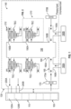
- an aircraft 100 has a cabin 110 that is divided into different zones 120, e.g., first and second zones 120A, 120B.
- a bay 130 of the aircraft 100 has an ECS (or system) 140.
- the bay 130 is typically located below the cabin 110.
- the system 140 includes a centralized mix manifold 150 that has at least one inlet 160 to receive cabin air from the cabin 110.
- the manifold includes first and second inlets 160A, 160B but these could be a single inlet.
- the at least one inlet 160 is fluidly coupled to at least one inlet duct 165.
- first and second inlet ducts 165A, 165B are fluidly coupled to the first and second inlets 160A, 160B.
- At least one recirculation fan 170 draws air from the cabin 110 to the mix manifold 150 via the at least one inlet duct 165.
- first and second recirculation fans 170A, 170B are provided which draw air from the cabin 110 into the inlets.
- Cabin return air typically flows from vents located near the intersection of the fuselage and the cabin floor. The return flow moves into a cheek area of the cargo bay from which the recirculation fans 170A, 170B and thermoelectric coolers (TECs), discussed below, draw in the return flow.
- the cabin air is mixed with conditioned bleed air that is processed through first and second AC packs 180A, 180B.
- the ECS packs 180A, 180B are typically located in outside of the aircraft pressure vessel in an unpressurized bay. As shown in FIG. 1 , the first and second AC packs 180A, 180B are fluidly coupled with the first and second inlet ducts 165A, 165B, between the first and second recirculation fans 170A, 170B and the mix manifold 150.
- the mix manifold 150 has outlets 190, e.g., first and second outlets 190A, 190B.
- the outlets 190 of the mix manifold 150 are fluidly coupled with the first and second zones 120A, 120B via zone ducts 200, e.g., first and second zone ducts 200A, 200B.
- air exiting the mix manifold 150 may need further conditioning by being heated or cooled by, e.g., 10 degrees Celsius, as a non-limiting example.
- trim modules e.g., first and second trim modules 210, 212
- each of the zone ducts 200A, 200B is fluidly coupled to one of the trim modules 210, 212.
- Each of the trim modules 210, 212 may have a same configuration as each other so that further reference will be to the trim module 210.
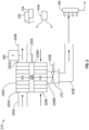
- the trim module 210 includes at least two heat exchangers 220, e.g., a first heat exchanger (a zone air heat exchanger) 220A and a second heat exchanger (a cabin return air heat exchanger) 220B.
- a thermoelectric cooler (TEC) module 230 is interposed and thermally coupled between the first and second heat exchangers 220A, 220B.
- the TEC modules can be Peltier devices that utilize the Peltier effect to create a heat flux at the junction of two different types of materials.
- a Peltier device (cooler, heater, or thermoelectric heat pump) is a solid-state active device which transfers heat from one side of the device to the other based on application of a voltage across the device. The direction of heat flow is based on the polarity of the voltage as will be understood by the skilled.
- the TEC module 230 is operationally coupled to the system 140, e.g., via leads 230A that receive power (e.g., supply voltage) and control signals from a system control 140A.
- power e.g., supply voltage
- voltage magnitude and polarity to the TEC module 230 will control its direction and magnitude of heat transfer, e.g., from the first heat exchanger 220A to the second heat exchanger 220B and vice versa.
- the TEC module 230 may include a plurality of TECs, 232, 234 configured as a circuit 236.
- the plurality of TECs 232, 234 may be electrically coupled in series or parallel, thermally coupled in series or parallel, or for either coupling, as a combination of series and parallel, and may be organized as a stack, to achieve a desired thermal effect, improve fault tolerances and increase heat transfer capacity.
- the heat exchangers 220A, 220B may be manufactured from aluminum.
- the trim module 210 may include various conduits 240.
- a mix manifold conduit 240A is fluidly coupled between an inlet 220A1 of the first heat exchanger 220A and, e.g., the first outlet 190A ( FIG. 1 ) of the mix manifold 150.
- a zone supply conduit 240B is fluidly coupled between an outlet 220A2 of the first heat exchanger 220A and, e.g., the first zone duct 200A ( FIG. 1 ) that is fluidly coupled to the first zone 120A.
- the heat exchanger 220B is intended to draw cabin return air from the ambient environment surrounding the mix manifold 150 into an inlet 220B1 using the exhaust fan 270 (discussed below).
- An exhaust conduit 240E is fluidly coupled between an outlet 220B2 of the second heat exchanger 220B and a low-pressure TEC exhaust (overboard) manifold 255 (or exhaust manifold, for simplicity) of the system 140.
- the trim module 210 may include a temperature sensor 260 located in the zone supply conduit 240B.
- An exhaust fan 270 may be fluidly coupled between the outlet 220B2 of the second heat exchanger 220B and the exhaust conduit 240E.
- the exhaust fan 270 may create negative pressure that draws air from bay 130 into the inlet 220B1 of the second heat exchanger 220B. This enables mixing of air from bay 130 and the cabin 110 within the second heat exchanger 220B when conditioning air from the mix manifold 150.
- the exhaust fan 270 is operationally coupled to the system 140, e.g., via leads 230B, to receive power (e.g., supply voltage) and control signals.
- the supply voltage and control signals to the exhaust fan 270 may differ from the supply voltage and control signals to the TEC module 230. That is, while the TEC module 230 may be controlled to alternatively direct heat transfer between the first and second heat exchangers 220A, 220B, the exhaust fan 270 is configured to exhaust waste air in one direction, i.e., away from the second heat exchanger 220B. The magnitude of the supply voltage to the exhaust fan 270 may be controlled to change the flow rate of air across the second heat exchanger 220B, depending on cooling or heating requirements. With the exhaust fan 270, waste air can be directed overboard from the exhaust manifold 255, or used for another purpose such as a driving a power turbine of an air cycle machine (ACM). Directing the exhaust air to the exhaust manifold 255 from the trim module 210 avoids adding unwanted heating and cooling of the aircraft cabin 130.
- ACM air cycle machine
- the TEC module 230 is configured to operate in a first mode or a second mode, depending on a temperature within the zone supply conduit 240B and a target temperature.
- the TEC module 230 In the first mode, the TEC module 230 is configured to transfer thermal energy from the first heat exchanger 220A to the second heat exchanger 220B.
- the TEC module 230 In the second mode, the TEC module 230 is configured to transfer thermal energy from the second heat exchanger 220B to the first heat exchanger 220A.
- a voltage magnitude and polarity to the TEC module 230 may be utilized to regulate the outlet temperatures of heat exchangers 220A, 220B to raise or lower the temperature of the mix manifold 150 by approximately 10 degrees Celsius, as indicated.
- the trim module 210 provides for a heating and cooling capability of a zone 120 by varying the magnitude and polarity of voltage applied to the TEC module 230.
- the magnitude of the voltage to the exhaust fan 270 may be controlled to change the flow rate of air across the second heat exchanger 220B, depending on cooling or heating requirements.
- a heating and cooling capability of the TEC module 230 enables optionally running the ECS 140 at a higher outlet temperature, which may translate into extra system capacity.
- a smaller ECS may be utilized. Locating the trim module 210 at the mix manifold 150 enables a low integration cost and weight for the trim module 210 because the system wiring and the exhaust manifold 255 are confined to the bay 130. As each trim module 210 is configured the same, there is a reduction in recurring manufacturing costs.
- the configuration enables an elimination of, e.g., diverter valves, which enables the ability to provide steady exhaust flow for other uses.
- Conventional pneumatic zone trim valves, trim injectors, mufflers, ducting, couplings and its associated mounting hardware is also eliminated.
Landscapes
- Engineering & Computer Science (AREA)
- Health & Medical Sciences (AREA)
- General Health & Medical Sciences (AREA)
- Pulmonology (AREA)
- Aviation & Aerospace Engineering (AREA)
- Physics & Mathematics (AREA)
- Mechanical Engineering (AREA)
- Thermal Sciences (AREA)
- General Engineering & Computer Science (AREA)
- Cooling Or The Like Of Electrical Apparatus (AREA)
Claims (5)
- Umweltkontrollsystem für ein Luftfahrzeug, umfassend:einen Mischverteiler (150) mit einem Einlass und einer Vielzahl von Auslässen;ein Rezirkulationsgebläse und ein Klimaaggregat, die mit dem Einlass fluidgekoppelt sind;eine Vielzahl von Verkleidungsmodulen (210) mit derselben Konfiguration zueinander, die an jeweilige der Vielzahl von Auslässen des Mischverteilers fluidgekoppelt sind, wobei sich jedes der Verkleidungsmodule (210) an dem Mischverteiler (150) befindet, wobei jedes Verkleidungsmodul umfasst:einen ersten Wärmetauscher (220A) mit einem Einlass und einem Auslass;einen zweiten Wärmetauscher (220B) mit einem Einlass und einem Auslass; undein thermoelektrisches Kühlermodul, TEC-Modul (230), das zwischen dem ersten und dem zweiten Wärmetauscher (220A, 220B) thermisch gekoppelt ist;eine Mischverteilerleitung (240A), die an den Einlass des ersten Wärmetauschers fluidgekoppelt ist;eine Zonenzufuhrleitung (240B), die an den Auslass des ersten Wärmetauschers fluidgekoppelt ist;eine Abluftleitung (240E), die an den Auslass des zweiten Wärmetauschers fluidgekoppelt ist,wobei für jedes TEC-Modul:das TEC-Modul (230) dazu konfiguriert ist, in Abhängigkeit von einer Temperatur innerhalb der Zonenzufuhrleitung (240B) und einer Solltemperatur in einem ersten Modus oder einem zweiten Modus zu arbeiten, undwobei:das TEC-Modul (230) dazu konfiguriert ist, in dem ersten Modus Wärmeenergie von dem ersten Wärmetauscher (220A) an den zweiten Wärmetauscher (220B) zu übertragen; unddas TEC-Modul (230) dazu konfiguriert ist, in dem zweiten Modus Wärmeenergie von dem zweiten Wärmetauscher (220B) an den ersten Wärmetauscher (220A) zu übertragen;einen Temperatursensor (260) in der Zonenzufuhrleitung (240B), wobei das TEC-Modul (230) dazu konfiguriert ist, in Abhängigkeit von der Temperatur, die von dem Temperatursensor (260) erfasst wird, und der Solltemperatur in dem ersten Modus oder dem zweiten Modus zu arbeiten;ein Abluftgebläse (270), das an den Auslass des zweiten Wärmetauschers (220B) und die Abluftleitung (240E) fluidgekoppelt ist, um Luft aus einer umliegenden Umgebung um den Mischverteiler (150) in den Einlass (220B1) des zweiten Wärmetauschers zu ziehen;wobei:die Vielzahl von Auslässen des Mischverteilers (150) an die Mischverteilerleitung (240A) von jeweiligen der Vielzahl von Verkleidungsmodulen (210) fluidgekoppelt ist; undeinen Abluftverteiler (255), der an die Abluftleitung (240E) des zweiten Wärmetauschers fluidgekoppelt ist.
- Umweltkontrollsystem nach Anspruch 1, wobei:
das TEC-Modul (230) eine Vielzahl von thermoelektrischen Kühlern beinhaltet, die als ein Kreislauf konfiguriert sind. - Luftfahrzeug, umfassend:eine Kabine (110), beinhaltend eine Zone, wobei die Zone einen Zonenkanal beinhaltet;eine Bucht (130), die sich unter der Kabine (110) befindet; unddas Umweltkontrollsystem nach Anspruch 1, das in der Bucht angeordnet ist, wobei die Zonenzufuhrleitung des ersten Wärmetauschers an den Zonenkanal der Zone fluidgekoppelt ist.
- Luftfahrzeug nach Anspruch 3, wobei:
das TEC-Modul (230) eine Vielzahl von thermoelektrischen Kühlern beinhaltet, die als ein Kreislauf konfiguriert sind. - Luftfahrzeug nach Anspruch 4, wobei:
die Vielzahl von thermoelektrischen Kühlern in Reihe oder parallel elektrisch gekoppelt ist; oder wobei:
die Vielzahl von thermoelektrischen Kühlern in Reihe oder parallel thermisch gekoppelt ist.
Applications Claiming Priority (1)
| Application Number | Priority Date | Filing Date | Title |
|---|---|---|---|
| US17/732,671 US12071247B2 (en) | 2022-04-29 | 2022-04-29 | Trim module with thermoelectric cooler |
Publications (2)
| Publication Number | Publication Date |
|---|---|
| EP4269246A1 EP4269246A1 (de) | 2023-11-01 |
| EP4269246B1 true EP4269246B1 (de) | 2025-03-19 |
Family
ID=86142957
Family Applications (1)
| Application Number | Title | Priority Date | Filing Date |
|---|---|---|---|
| EP23169283.1A Active EP4269246B1 (de) | 2022-04-29 | 2023-04-21 | Verkleidungsmodul mit thermoelektrischem kühler |
Country Status (2)
| Country | Link |
|---|---|
| US (1) | US12071247B2 (de) |
| EP (1) | EP4269246B1 (de) |
Families Citing this family (1)
| Publication number | Priority date | Publication date | Assignee | Title |
|---|---|---|---|---|
| US11999492B2 (en) * | 2022-05-19 | 2024-06-04 | Textron Innovations Inc. | Electric temperature control system for unpressurized aircraft |
Family Cites Families (13)
| Publication number | Priority date | Publication date | Assignee | Title |
|---|---|---|---|---|
| DE3333078A1 (de) | 1983-09-14 | 1985-03-21 | Atis Assmann GmbH, 6380 Bad Homburg | Video-ueberwachungseinrichtung |
| US5524439A (en) | 1993-11-22 | 1996-06-11 | Amerigon, Inc. | Variable temperature seat climate control system |
| US5584183A (en) | 1994-02-18 | 1996-12-17 | Solid State Cooling Systems | Thermoelectric heat exchanger |
| US6530231B1 (en) * | 2000-09-22 | 2003-03-11 | Te Technology, Inc. | Thermoelectric assembly sealing member and thermoelectric assembly incorporating same |
| DE102006005037B4 (de) | 2006-02-03 | 2012-03-29 | Airbus Operations Gmbh | Klimatisierungsanordnung für ein Flugzeug mit mehreren individuell temperaturregelbaren Klimazonen |
| US20100274396A1 (en) * | 2009-04-24 | 2010-10-28 | Gm Global Technology Operations, Inc. | Thermoelectric climate control |
| KR101343736B1 (ko) * | 2011-11-22 | 2013-12-19 | 갑을오토텍(주) | 차량용 냉난방기의 응축수 제거장치 |
| US9783309B2 (en) * | 2013-07-16 | 2017-10-10 | The Boeing Company | Methods and device for mixing airflows in environmental control systems |
| US20180148181A1 (en) | 2016-11-30 | 2018-05-31 | Hamilton Sundstrand Corporation | Air distribution manifold with integral multizone tec trim system |
| US20180162535A1 (en) | 2016-12-08 | 2018-06-14 | Hamilton Sundstrand Corporation | Air distribution system with recirculating zone trim tec |
| EP3598042B1 (de) * | 2017-03-15 | 2022-09-14 | LG Electronics Inc. | Kühlschrank |
| US20200377216A1 (en) | 2019-05-31 | 2020-12-03 | Hamilton Sundstrand Corporation | Aircraft cabin air thermodynamic control |
| US12392529B2 (en) * | 2020-04-13 | 2025-08-19 | The Boeing Company | Air distribution system and method including a thermocouple device |
-
2022
- 2022-04-29 US US17/732,671 patent/US12071247B2/en active Active
-
2023
- 2023-04-21 EP EP23169283.1A patent/EP4269246B1/de active Active
Also Published As
| Publication number | Publication date |
|---|---|
| US12071247B2 (en) | 2024-08-27 |
| US20230348068A1 (en) | 2023-11-02 |
| EP4269246A1 (de) | 2023-11-01 |
Similar Documents
| Publication | Publication Date | Title |
|---|---|---|
| US10752365B2 (en) | Method and device for thermal control of a plurality of cabins of a vehicle | |
| CN103079956B (zh) | 包括分离的制冷循环的飞行器空气调节系统 | |
| EP1979232B1 (de) | Luftklimatisierungsanordnung für ein luftfahrzeug mit mehreren einzeln temperaturregelbaren klimazonen | |
| US4482114A (en) | Integrated thermal anti-icing and environmental control system | |
| US10202197B2 (en) | Aircraft air conditioning system with an electrically driven ambient air compressor and method for operating such an aircraft air conditioning system | |
| EP3333078B1 (de) | Luftverteilungssystem mit thermoelektrischer kühlvorrichtung zur trimmung von rückführungszonen | |
| JP5084720B2 (ja) | 再循環させた空気を用いた貨物区画空気調整のためのシステムおよび方法 | |
| US9623973B2 (en) | Cooling concept for fuel cell emergency power supply | |
| EP3733518B1 (de) | Reverse-bootstrap-luftzyklusmaschine | |
| US9561856B2 (en) | Heat exchanger, cooling system and method for operating a heat exchanger and a cooling system | |
| US9469407B2 (en) | Fluid temperature control installation for rotorcraft, associating a system for cooling a power plant with a system for heating a cabin | |
| EP3590839B1 (de) | Druckoptimierte bereitstellung von kabinenbedruckung und komponentenkühlung | |
| EP3415433B1 (de) | Hocheffizientes, elektrisch betriebenes umweltkontrollsystem | |
| US9598175B2 (en) | Modular environmental air conditioning system | |
| EP4269246B1 (de) | Verkleidungsmodul mit thermoelektrischem kühler | |
| US7922118B2 (en) | System for producing process air | |
| EP3330181B1 (de) | Luftverteilungsblock mit integriertem mehrzonigem thermoelektrischem tec trimmsystem | |
| GB2166542A (en) | Air conditioning systems for aircraft cabins | |
| EP3760544B1 (de) | Adaptiver plattenrippenwärmetauscher | |
| CN111516882B (zh) | 飞机机舱的加热通风系统 |
Legal Events
| Date | Code | Title | Description |
|---|---|---|---|
| PUAI | Public reference made under article 153(3) epc to a published international application that has entered the european phase |
Free format text: ORIGINAL CODE: 0009012 |
|
| STAA | Information on the status of an ep patent application or granted ep patent |
Free format text: STATUS: THE APPLICATION HAS BEEN PUBLISHED |
|
| AK | Designated contracting states |
Kind code of ref document: A1 Designated state(s): AL AT BE BG CH CY CZ DE DK EE ES FI FR GB GR HR HU IE IS IT LI LT LU LV MC ME MK MT NL NO PL PT RO RS SE SI SK SM TR |
|
| STAA | Information on the status of an ep patent application or granted ep patent |
Free format text: STATUS: REQUEST FOR EXAMINATION WAS MADE |
|
| 17P | Request for examination filed |
Effective date: 20240424 |
|
| RBV | Designated contracting states (corrected) |
Designated state(s): AL AT BE BG CH CY CZ DE DK EE ES FI FR GB GR HR HU IE IS IT LI LT LU LV MC ME MK MT NL NO PL PT RO RS SE SI SK SM TR |
|
| GRAP | Despatch of communication of intention to grant a patent |
Free format text: ORIGINAL CODE: EPIDOSNIGR1 |
|
| STAA | Information on the status of an ep patent application or granted ep patent |
Free format text: STATUS: GRANT OF PATENT IS INTENDED |
|
| INTG | Intention to grant announced |
Effective date: 20241024 |
|
| GRAS | Grant fee paid |
Free format text: ORIGINAL CODE: EPIDOSNIGR3 |
|
| GRAA | (expected) grant |
Free format text: ORIGINAL CODE: 0009210 |
|
| STAA | Information on the status of an ep patent application or granted ep patent |
Free format text: STATUS: THE PATENT HAS BEEN GRANTED |
|
| AK | Designated contracting states |
Kind code of ref document: B1 Designated state(s): AL AT BE BG CH CY CZ DE DK EE ES FI FR GB GR HR HU IE IS IT LI LT LU LV MC ME MK MT NL NO PL PT RO RS SE SI SK SM TR |
|
| REG | Reference to a national code |
Ref country code: GB Ref legal event code: FG4D |
|
| REG | Reference to a national code |
Ref country code: CH Ref legal event code: EP |
|
| REG | Reference to a national code |
Ref country code: DE Ref legal event code: R096 Ref document number: 602023002439 Country of ref document: DE |
|
| REG | Reference to a national code |
Ref country code: IE Ref legal event code: FG4D |
|
| PG25 | Lapsed in a contracting state [announced via postgrant information from national office to epo] |
Ref country code: RS Free format text: LAPSE BECAUSE OF FAILURE TO SUBMIT A TRANSLATION OF THE DESCRIPTION OR TO PAY THE FEE WITHIN THE PRESCRIBED TIME-LIMIT Effective date: 20250619 |
|
| PG25 | Lapsed in a contracting state [announced via postgrant information from national office to epo] |
Ref country code: FI Free format text: LAPSE BECAUSE OF FAILURE TO SUBMIT A TRANSLATION OF THE DESCRIPTION OR TO PAY THE FEE WITHIN THE PRESCRIBED TIME-LIMIT Effective date: 20250319 |
|
| PGFP | Annual fee paid to national office [announced via postgrant information from national office to epo] |
Ref country code: DE Payment date: 20250319 Year of fee payment: 3 |
|
| REG | Reference to a national code |
Ref country code: LT Ref legal event code: MG9D |
|
| PG25 | Lapsed in a contracting state [announced via postgrant information from national office to epo] |
Ref country code: NO Free format text: LAPSE BECAUSE OF FAILURE TO SUBMIT A TRANSLATION OF THE DESCRIPTION OR TO PAY THE FEE WITHIN THE PRESCRIBED TIME-LIMIT Effective date: 20250619 |
|
| PG25 | Lapsed in a contracting state [announced via postgrant information from national office to epo] |
Ref country code: HR Free format text: LAPSE BECAUSE OF FAILURE TO SUBMIT A TRANSLATION OF THE DESCRIPTION OR TO PAY THE FEE WITHIN THE PRESCRIBED TIME-LIMIT Effective date: 20250319 |
|
| PG25 | Lapsed in a contracting state [announced via postgrant information from national office to epo] |
Ref country code: LV Free format text: LAPSE BECAUSE OF FAILURE TO SUBMIT A TRANSLATION OF THE DESCRIPTION OR TO PAY THE FEE WITHIN THE PRESCRIBED TIME-LIMIT Effective date: 20250319 |
|
| PG25 | Lapsed in a contracting state [announced via postgrant information from national office to epo] |
Ref country code: GR Free format text: LAPSE BECAUSE OF FAILURE TO SUBMIT A TRANSLATION OF THE DESCRIPTION OR TO PAY THE FEE WITHIN THE PRESCRIBED TIME-LIMIT Effective date: 20250620 Ref country code: BG Free format text: LAPSE BECAUSE OF FAILURE TO SUBMIT A TRANSLATION OF THE DESCRIPTION OR TO PAY THE FEE WITHIN THE PRESCRIBED TIME-LIMIT Effective date: 20250319 |
|
| REG | Reference to a national code |
Ref country code: NL Ref legal event code: MP Effective date: 20250319 |
|
| REG | Reference to a national code |
Ref country code: AT Ref legal event code: MK05 Ref document number: 1776783 Country of ref document: AT Kind code of ref document: T Effective date: 20250319 |
|
| PG25 | Lapsed in a contracting state [announced via postgrant information from national office to epo] |
Ref country code: NL Free format text: LAPSE BECAUSE OF FAILURE TO SUBMIT A TRANSLATION OF THE DESCRIPTION OR TO PAY THE FEE WITHIN THE PRESCRIBED TIME-LIMIT Effective date: 20250319 |
|
| PG25 | Lapsed in a contracting state [announced via postgrant information from national office to epo] |
Ref country code: SE Free format text: LAPSE BECAUSE OF FAILURE TO SUBMIT A TRANSLATION OF THE DESCRIPTION OR TO PAY THE FEE WITHIN THE PRESCRIBED TIME-LIMIT Effective date: 20250319 |
|
| PG25 | Lapsed in a contracting state [announced via postgrant information from national office to epo] |
Ref country code: SM Free format text: LAPSE BECAUSE OF FAILURE TO SUBMIT A TRANSLATION OF THE DESCRIPTION OR TO PAY THE FEE WITHIN THE PRESCRIBED TIME-LIMIT Effective date: 20250319 |
|
| PG25 | Lapsed in a contracting state [announced via postgrant information from national office to epo] |
Ref country code: ES Free format text: LAPSE BECAUSE OF FAILURE TO SUBMIT A TRANSLATION OF THE DESCRIPTION OR TO PAY THE FEE WITHIN THE PRESCRIBED TIME-LIMIT Effective date: 20250319 Ref country code: PT Free format text: LAPSE BECAUSE OF FAILURE TO SUBMIT A TRANSLATION OF THE DESCRIPTION OR TO PAY THE FEE WITHIN THE PRESCRIBED TIME-LIMIT Effective date: 20250721 |
|
| PG25 | Lapsed in a contracting state [announced via postgrant information from national office to epo] |
Ref country code: PL Free format text: LAPSE BECAUSE OF FAILURE TO SUBMIT A TRANSLATION OF THE DESCRIPTION OR TO PAY THE FEE WITHIN THE PRESCRIBED TIME-LIMIT Effective date: 20250319 Ref country code: IT Free format text: LAPSE BECAUSE OF FAILURE TO SUBMIT A TRANSLATION OF THE DESCRIPTION OR TO PAY THE FEE WITHIN THE PRESCRIBED TIME-LIMIT Effective date: 20250319 |
|
| PG25 | Lapsed in a contracting state [announced via postgrant information from national office to epo] |
Ref country code: AT Free format text: LAPSE BECAUSE OF FAILURE TO SUBMIT A TRANSLATION OF THE DESCRIPTION OR TO PAY THE FEE WITHIN THE PRESCRIBED TIME-LIMIT Effective date: 20250319 |
|
| PG25 | Lapsed in a contracting state [announced via postgrant information from national office to epo] |
Ref country code: EE Free format text: LAPSE BECAUSE OF FAILURE TO SUBMIT A TRANSLATION OF THE DESCRIPTION OR TO PAY THE FEE WITHIN THE PRESCRIBED TIME-LIMIT Effective date: 20250319 Ref country code: CZ Free format text: LAPSE BECAUSE OF FAILURE TO SUBMIT A TRANSLATION OF THE DESCRIPTION OR TO PAY THE FEE WITHIN THE PRESCRIBED TIME-LIMIT Effective date: 20250319 |
|
| PG25 | Lapsed in a contracting state [announced via postgrant information from national office to epo] |
Ref country code: RO Free format text: LAPSE BECAUSE OF FAILURE TO SUBMIT A TRANSLATION OF THE DESCRIPTION OR TO PAY THE FEE WITHIN THE PRESCRIBED TIME-LIMIT Effective date: 20250319 |
|
| PG25 | Lapsed in a contracting state [announced via postgrant information from national office to epo] |
Ref country code: SK Free format text: LAPSE BECAUSE OF FAILURE TO SUBMIT A TRANSLATION OF THE DESCRIPTION OR TO PAY THE FEE WITHIN THE PRESCRIBED TIME-LIMIT Effective date: 20250319 |
|
| PG25 | Lapsed in a contracting state [announced via postgrant information from national office to epo] |
Ref country code: IS Free format text: LAPSE BECAUSE OF FAILURE TO SUBMIT A TRANSLATION OF THE DESCRIPTION OR TO PAY THE FEE WITHIN THE PRESCRIBED TIME-LIMIT Effective date: 20250719 |
|
| PG25 | Lapsed in a contracting state [announced via postgrant information from national office to epo] |
Ref country code: LU Free format text: LAPSE BECAUSE OF NON-PAYMENT OF DUE FEES Effective date: 20250421 |
|
| PG25 | Lapsed in a contracting state [announced via postgrant information from national office to epo] |
Ref country code: MC Free format text: LAPSE BECAUSE OF FAILURE TO SUBMIT A TRANSLATION OF THE DESCRIPTION OR TO PAY THE FEE WITHIN THE PRESCRIBED TIME-LIMIT Effective date: 20250319 |
|
| REG | Reference to a national code |
Ref country code: DE Ref legal event code: R097 Ref document number: 602023002439 Country of ref document: DE |
|
| REG | Reference to a national code |
Ref country code: BE Ref legal event code: MM Effective date: 20250430 |
|
| PG25 | Lapsed in a contracting state [announced via postgrant information from national office to epo] |
Ref country code: DK Free format text: LAPSE BECAUSE OF FAILURE TO SUBMIT A TRANSLATION OF THE DESCRIPTION OR TO PAY THE FEE WITHIN THE PRESCRIBED TIME-LIMIT Effective date: 20250319 |
|
| PG25 | Lapsed in a contracting state [announced via postgrant information from national office to epo] |
Ref country code: BE Free format text: LAPSE BECAUSE OF NON-PAYMENT OF DUE FEES Effective date: 20250430 |
|
| PLBE | No opposition filed within time limit |
Free format text: ORIGINAL CODE: 0009261 |
|
| STAA | Information on the status of an ep patent application or granted ep patent |
Free format text: STATUS: NO OPPOSITION FILED WITHIN TIME LIMIT |
|
| REG | Reference to a national code |
Ref country code: CH Ref legal event code: L10 Free format text: ST27 STATUS EVENT CODE: U-0-0-L10-L00 (AS PROVIDED BY THE NATIONAL OFFICE) Effective date: 20260128 |
|
| 26N | No opposition filed |
Effective date: 20251222 |
|
| PG25 | Lapsed in a contracting state [announced via postgrant information from national office to epo] |
Ref country code: IE Free format text: LAPSE BECAUSE OF NON-PAYMENT OF DUE FEES Effective date: 20250421 |
|
| PGFP | Annual fee paid to national office [announced via postgrant information from national office to epo] |
Ref country code: FR Payment date: 20260320 Year of fee payment: 4 |