EP4269338A1 - Matériau actif d'électrode négative, batterie secondaire et procédé de production de particules de graphite artificiel - Google Patents
Matériau actif d'électrode négative, batterie secondaire et procédé de production de particules de graphite artificiel Download PDFInfo
- Publication number
- EP4269338A1 EP4269338A1 EP23168001.8A EP23168001A EP4269338A1 EP 4269338 A1 EP4269338 A1 EP 4269338A1 EP 23168001 A EP23168001 A EP 23168001A EP 4269338 A1 EP4269338 A1 EP 4269338A1
- Authority
- EP
- European Patent Office
- Prior art keywords
- negative electrode
- active material
- electrode active
- artificial graphite
- graphite particles
- Prior art date
- Legal status (The legal status is an assumption and is not a legal conclusion. Google has not performed a legal analysis and makes no representation as to the accuracy of the status listed.)
- Pending
Links
Images


Classifications
-
- H—ELECTRICITY
- H01—ELECTRIC ELEMENTS
- H01M—PROCESSES OR MEANS, e.g. BATTERIES, FOR THE DIRECT CONVERSION OF CHEMICAL ENERGY INTO ELECTRICAL ENERGY
- H01M4/00—Electrodes
- H01M4/02—Electrodes composed of, or comprising, active material
- H01M4/36—Selection of substances as active materials, active masses, active liquids
- H01M4/58—Selection of substances as active materials, active masses, active liquids of inorganic compounds other than oxides or hydroxides, e.g. sulfides, selenides, tellurides, halogenides or LiCoFy; of polyanionic structures, e.g. phosphates, silicates or borates
- H01M4/583—Carbonaceous material, e.g. graphite-intercalation compounds or CFx
-
- C—CHEMISTRY; METALLURGY
- C01—INORGANIC CHEMISTRY
- C01B—NON-METALLIC ELEMENTS; COMPOUNDS THEREOF; METALLOIDS OR COMPOUNDS THEREOF NOT COVERED BY SUBCLASS C01C
- C01B32/00—Carbon; Compounds thereof
- C01B32/20—Graphite
- C01B32/205—Preparation
-
- C—CHEMISTRY; METALLURGY
- C01—INORGANIC CHEMISTRY
- C01B—NON-METALLIC ELEMENTS; COMPOUNDS THEREOF; METALLOIDS OR COMPOUNDS THEREOF NOT COVERED BY SUBCLASS C01C
- C01B32/00—Carbon; Compounds thereof
- C01B32/20—Graphite
-
- H—ELECTRICITY
- H01—ELECTRIC ELEMENTS
- H01M—PROCESSES OR MEANS, e.g. BATTERIES, FOR THE DIRECT CONVERSION OF CHEMICAL ENERGY INTO ELECTRICAL ENERGY
- H01M10/00—Secondary cells; Manufacture thereof
- H01M10/05—Accumulators with non-aqueous electrolyte
- H01M10/052—Li-accumulators
- H01M10/0525—Rocking-chair batteries, i.e. batteries with lithium insertion or intercalation in both electrodes; Lithium-ion batteries
-
- H—ELECTRICITY
- H01—ELECTRIC ELEMENTS
- H01M—PROCESSES OR MEANS, e.g. BATTERIES, FOR THE DIRECT CONVERSION OF CHEMICAL ENERGY INTO ELECTRICAL ENERGY
- H01M4/00—Electrodes
- H01M4/02—Electrodes composed of, or comprising, active material
- H01M4/04—Processes of manufacture in general
- H01M4/0471—Processes of manufacture in general involving thermal treatment, e.g. firing, sintering, backing particulate active material, thermal decomposition, pyrolysis
-
- H—ELECTRICITY
- H01—ELECTRIC ELEMENTS
- H01M—PROCESSES OR MEANS, e.g. BATTERIES, FOR THE DIRECT CONVERSION OF CHEMICAL ENERGY INTO ELECTRICAL ENERGY
- H01M4/00—Electrodes
- H01M4/02—Electrodes composed of, or comprising, active material
- H01M4/13—Electrodes for accumulators with non-aqueous electrolyte, e.g. for lithium-accumulators; Processes of manufacture thereof
- H01M4/133—Electrodes based on carbonaceous material, e.g. graphite-intercalation compounds or CFx
-
- H—ELECTRICITY
- H01—ELECTRIC ELEMENTS
- H01M—PROCESSES OR MEANS, e.g. BATTERIES, FOR THE DIRECT CONVERSION OF CHEMICAL ENERGY INTO ELECTRICAL ENERGY
- H01M4/00—Electrodes
- H01M4/02—Electrodes composed of, or comprising, active material
- H01M4/36—Selection of substances as active materials, active masses, active liquids
- H01M4/58—Selection of substances as active materials, active masses, active liquids of inorganic compounds other than oxides or hydroxides, e.g. sulfides, selenides, tellurides, halogenides or LiCoFy; of polyanionic structures, e.g. phosphates, silicates or borates
- H01M4/583—Carbonaceous material, e.g. graphite-intercalation compounds or CFx
- H01M4/587—Carbonaceous material, e.g. graphite-intercalation compounds or CFx for inserting or intercalating light metals
-
- C—CHEMISTRY; METALLURGY
- C01—INORGANIC CHEMISTRY
- C01B—NON-METALLIC ELEMENTS; COMPOUNDS THEREOF; METALLOIDS OR COMPOUNDS THEREOF NOT COVERED BY SUBCLASS C01C
- C01B2204/00—Structure or properties of graphene
- C01B2204/20—Graphene characterized by its properties
- C01B2204/22—Electronic properties
-
- C—CHEMISTRY; METALLURGY
- C01—INORGANIC CHEMISTRY
- C01P—INDEXING SCHEME RELATING TO STRUCTURAL AND PHYSICAL ASPECTS OF SOLID INORGANIC COMPOUNDS
- C01P2002/00—Crystal-structural characteristics
- C01P2002/70—Crystal-structural characteristics defined by measured X-ray, neutron or electron diffraction data
- C01P2002/72—Crystal-structural characteristics defined by measured X-ray, neutron or electron diffraction data by d-values or two theta-values, e.g. as X-ray diagram
-
- C—CHEMISTRY; METALLURGY
- C01—INORGANIC CHEMISTRY
- C01P—INDEXING SCHEME RELATING TO STRUCTURAL AND PHYSICAL ASPECTS OF SOLID INORGANIC COMPOUNDS
- C01P2002/00—Crystal-structural characteristics
- C01P2002/70—Crystal-structural characteristics defined by measured X-ray, neutron or electron diffraction data
- C01P2002/78—Crystal-structural characteristics defined by measured X-ray, neutron or electron diffraction data by stacking-plane distances or stacking sequences
-
- C—CHEMISTRY; METALLURGY
- C01—INORGANIC CHEMISTRY
- C01P—INDEXING SCHEME RELATING TO STRUCTURAL AND PHYSICAL ASPECTS OF SOLID INORGANIC COMPOUNDS
- C01P2002/00—Crystal-structural characteristics
- C01P2002/80—Crystal-structural characteristics defined by measured data other than those specified in group C01P2002/70
- C01P2002/82—Crystal-structural characteristics defined by measured data other than those specified in group C01P2002/70 by IR- or Raman-data
-
- C—CHEMISTRY; METALLURGY
- C01—INORGANIC CHEMISTRY
- C01P—INDEXING SCHEME RELATING TO STRUCTURAL AND PHYSICAL ASPECTS OF SOLID INORGANIC COMPOUNDS
- C01P2006/00—Physical properties of inorganic compounds
- C01P2006/16—Pore diameter
-
- C—CHEMISTRY; METALLURGY
- C01—INORGANIC CHEMISTRY
- C01P—INDEXING SCHEME RELATING TO STRUCTURAL AND PHYSICAL ASPECTS OF SOLID INORGANIC COMPOUNDS
- C01P2006/00—Physical properties of inorganic compounds
- C01P2006/40—Electric properties
-
- C—CHEMISTRY; METALLURGY
- C01—INORGANIC CHEMISTRY
- C01P—INDEXING SCHEME RELATING TO STRUCTURAL AND PHYSICAL ASPECTS OF SOLID INORGANIC COMPOUNDS
- C01P2006/00—Physical properties of inorganic compounds
- C01P2006/90—Other properties not specified above
-
- H—ELECTRICITY
- H01—ELECTRIC ELEMENTS
- H01M—PROCESSES OR MEANS, e.g. BATTERIES, FOR THE DIRECT CONVERSION OF CHEMICAL ENERGY INTO ELECTRICAL ENERGY
- H01M4/00—Electrodes
- H01M4/02—Electrodes composed of, or comprising, active material
- H01M2004/021—Physical characteristics, e.g. porosity, surface area
-
- H—ELECTRICITY
- H01—ELECTRIC ELEMENTS
- H01M—PROCESSES OR MEANS, e.g. BATTERIES, FOR THE DIRECT CONVERSION OF CHEMICAL ENERGY INTO ELECTRICAL ENERGY
- H01M4/00—Electrodes
- H01M4/02—Electrodes composed of, or comprising, active material
- H01M2004/026—Electrodes composed of, or comprising, active material characterised by the polarity
- H01M2004/027—Negative electrodes
-
- Y—GENERAL TAGGING OF NEW TECHNOLOGICAL DEVELOPMENTS; GENERAL TAGGING OF CROSS-SECTIONAL TECHNOLOGIES SPANNING OVER SEVERAL SECTIONS OF THE IPC; TECHNICAL SUBJECTS COVERED BY FORMER USPC CROSS-REFERENCE ART COLLECTIONS [XRACs] AND DIGESTS
- Y02—TECHNOLOGIES OR APPLICATIONS FOR MITIGATION OR ADAPTATION AGAINST CLIMATE CHANGE
- Y02E—REDUCTION OF GREENHOUSE GAS [GHG] EMISSIONS, RELATED TO ENERGY GENERATION, TRANSMISSION OR DISTRIBUTION
- Y02E60/00—Enabling technologies; Technologies with a potential or indirect contribution to GHG emissions mitigation
- Y02E60/10—Energy storage using batteries
Definitions
- the present disclosure relates to a negative electrode active material including artificial graphite particles.
- the present disclosure also relates to a secondary battery using the negative electrode active material.
- the present disclosure also relates to a method for producing the artificial graphite particles.
- secondary batteries such as lithium ion secondary batteries are suitably used for, for example, portable power supplies for devices such as personal computers and portable terminals, and power supplies for driving vehicles such as battery electric vehicles (BEVs), hybrid electric vehicles (HEVs), and plug-in hybrid electric vehicles (PHEVs).
- BEVs battery electric vehicles
- HEVs hybrid electric vehicles
- PHEVs plug-in hybrid electric vehicles
- Electrodes of secondary batteries especially lithium ion secondary batteries, use active materials capable of absorbing and desorbing ions serving as charge carriers.
- the active material expands and contracts with absorption and desorption of these ions, and thus, the volume of the electrode changes in charging and discharging the secondary battery.
- suppression of this volume change of electrodes have been an issue for many years.
- Patent Document 1 proposes to suppress expansion of a negative electrode in the thickness direction by orienting a graphite layer perpendicularly to a negative electrode current collector to some degree.
- Patent Document 1 Japanese Patent No. 6625336
- a negative electrode active material (1) disclosed herein includes artificial graphite particles having a plurality of internal voids.
- the artificial graphite particles have a porosity of 0.7 to 15%.
- circular approximation is then performed on internal voids having cross-sectional areas of 1000 nm 2 or more, and circularities of 20 or more of the internal voids arbitrarily selected in each particle are determined, the internal voids have an average circularity of 0.1 to 0.6. This configuration provides a negative electrode active material capable of suppressing expansion of the negative electrode.
- the artificial graphite particles have a porosity of 8 to 15% in the negative electrode active material (1). This configuration further suppresses expansion of the negative electrode.
- the internal voids have an average circularity of 0.3 to 0.6 in the negative electrode active material (1) or (2). This configuration further suppresses expansion of the negative electrode.
- a ratio (I G /I D ) of a G band peak intensity (I G ) to a D band peak intensity (I D ) of the artificial graphite particles determined by Raman spectroscopy is 1.5 to 60 in any one of the negative electrode active materials (1) to (3).
- the internal voids are oriented in parallel with the graphite layer, and expansion of the negative electrode is further suppressed.
- the capacity increases.
- an interplanar distance d 002 of a (002) plane of graphite crystal of the artificial graphite particles determined by a powder X-ray diffraction analysis is 3.36 ⁇ to 3.38 ⁇ in any one of the negative electrode active materials (1) to (4).
- the internal voids are oriented in parallel with the graphite layer, and expansion of the negative electrode is further suppressed.
- a secondary battery (6) disclosed herein includes: a positive electrode; a negative electrode; and an electrolyte.
- the negative electrode includes any one of the negative electrode active materials (1) to (5). This configuration provides a secondary battery in which expansion of the negative electrode is suppressed.
- a method for producing artificial graphite particles (7) disclosed herein includes heating a graphite precursor from 1000°C to 2600°C or more within five hours to graphitize the graphite precursor.
- a sulfur concentration in the graphite precursor is 0.4% or more and 7% or less. This configuration can produce a negative electrode active material capable of suppressing expansion of the negative electrode.
- a method for producing artificial graphite particles (8) disclosed herein the graphite precursor is heated from 1000°C to 2800°C or more within five hours to graphitize the graphite precursor in the production method (7).
- This configuration is more advantageous in producing a negative electrode active material capable of suppressing expansion of the negative electrode.
- the heating is performed by high-frequency induction heating in the production method (7) or (8). This configuration enables heating at a significantly high temperature rise rate.
- a “secondary battery” herein refers to a power storage device capable of being repeatedly charged and discharged, and includes a so-called storage battery and a power storage element such as an electric double layer capacitor.
- a “lithium ion secondary battery” herein refers to a secondary battery that uses lithium ions as charge carriers and performs charge and discharge by movement of charges accompanying lithium ions between positive and negative electrodes.
- a negative electrode active material includes artificial graphite particles having a plurality of internal voids.
- the artificial graphite particles have a porosity of 0.7 to 15%.
- circular approximation is then performed on internal voids having cross-sectional areas of 1000 nm 2 or more, and circularities of 20 or more of the internal voids arbitrarily selected in each particle are determined, the internal voids have an average circularity of 0.1 to 0.6.
- FIG. 1 is an illustration for a concept of artificial graphite particles included in the negative electrode active material according to this embodiment, and is a schematic cross-sectional view of an example of the artificial graphite particles.
- artificial graphite particles 10 include a graphite portion 12 and a plurality of internal voids 14.
- the plurality of internal voids 14 are present as independent voids.
- an average circularity is determined by using 20 or more of internal voids
- the number of internal voids 14 included in one artificial graphite particle 10 is 20 or more.
- each of the internal voids 14 is an ellipse.
- the shape of each internal void 14, however, is not limited thereto.
- the internal void 14 may be, for example, an approximate rectangle or an indefinite shape.
- the position, number, and the like of the internal voids 14 are not limited to the examples illustrated in FIG. 1 .
- a porosity of the particles is used as an index.
- the artificial graphite particles 10 has the internal voids 14 in such an amount that the artificial graphite particles 10 have a porosity of 0.7 to 15%.
- Artificial graphite obtained by graphitization of a graphite precursor generally has no internal voids.
- circularity of a figure is used as an index.
- the circularity is a value calculated by 4 ⁇ S/L 2 (where S is an area of a figure, and L is a perimeter of the figure).
- a perfect circle has a circularity of one, and it means that as the circularity decreases, the figure gradually deviates from the perfect circle.
- circular approximation is performed on internal voids 14 having cross-sectional areas of 1000 nm 2 or more.
- S is an area of internal voids 14 subjected to circular approximation
- L is a perimeter of the internal voids 14 subjected to circular approximation. Since the internal voids 14 are subjected to the circular approximation, as the circularity decreases, the internal voids 14 approach flat.
- the average circularity is 0.1 to 0.6.
- the artificial graphite particles 10 according to this embodiment have a specific amount of internal voids 14 having a specific circularity, whereby expansion of the negative electrode using the artificial graphite particles 10 can be suppressed. This is supposed to be because of the following reasons.
- an interplanar distance of graphite crystal expands, and accordingly, graphite particles expand.
- the artificial graphite particles 10 include a specific amount of internal voids 14 having a specific circularity, the expansion of the interplanar distance of graphite crystal can be thereby absorbed.
- the circularity of internal voids subjected to circular approximation is within a predetermined range (i.e., the internal voids have an elongated shape) in this example, the expansion of the interplanar distance of graphite crystal is easily absorbed.
- a change in the volume of the artificial graphite particles 10 can be effectively reduced. Consequently, the expansion of the negative electrode using the artificial graphite particles 10 can be suppressed.
- the porosity of the artificial graphite particles 10 is desirably 8 to 15%. It should be noted that the porosity is determined as a percentage (%) of the total area of internal voids with respect to the area of the entire particle in a cross-sectional electron micrograph of the artificial graphite particles 10.
- the porosity can be determined in the following manner, for example.
- a material or a member e.g., negative electrode active material layer of a negative electrode
- artificial graphite particles is subjected to ion milling so that a cross section of the material or the member is exposed.
- a scanning electron microscopic (SEM) image of this cross section is obtained, and in this SEM image, a graphite portion and void portions are made distinct with image analysis software and are subjected to binarization.
- the area of the graphite portion and the area of the void portions are determined, and [(void portion total area)/ ⁇ (graphite portion area) + (void portion total area) ⁇ ] ⁇ 100 is calculated. This value is obtained for 10 or more particles, and an average of these values is used as a porosity.
- the circularity of the artificial graphite particles 10 is desirably 0.3 to 0.6, and more desirably 0.45 to 0.6. It should be noted that the circularity can be determined in the following manner, for example.
- a material or a member (e.g., negative electrode active material of a negative electrode) including artificial graphite particles is subjected to ion milling so that a cross section of the material or the member is exposed.
- An SEM image of this cross section is obtained, and in this SEM image, a graphite portion and void portions are made distinct with image analysis software and are subjected to binarization.
- Image J distributed by National Institutes of Health can be used, for example.
- the internal voids 14 are oriented in a predetermined direction.
- the internal voids 14 are desirably oriented in parallel with a graphite layer (i.e., a graphene plane).
- a graphite layer i.e., a graphene plane.
- the major axis of each internal void 14 subjected to circular approximation can be oriented in parallel with the graphite layer.
- the crystallinity of the artificial graphite particles 10 can be evaluated by using a ratio (I G /I D ) of a G band peak intensity (I G ) to a D band peak intensity (I D ) determined by Raman spectroscopy.
- the ratio (I G /I D ) is desirably 1.5 or more because crystal growth sufficiently progresses so that internal voids sufficiently develop and are highly oriented in the direction in which the graphite layer extends in the artificial graphite particles 10.
- the ratio (I G /I D ) is desirably 60 or less because defect sites that allow lithium ions to enter particles are appropriately formed so that the capacity of the negative electrode active material increases.
- the D band peak intensity (I D ) and the G band peak intensity (I G ) can be obtained as the intensities of peaks appearing around 1360 cm -1 and around 1580 cm -1 , respectively, in Raman spectroscopic measurement, using argon ion laser light, of the artificial graphite particles 10.
- the crystallinity of the artificial graphite particles 10 can also be evaluated by using an interplanar distance d 002 of a (002) plane of graphite crystal of the artificial graphite particles 10.
- the interplanar distance d 002 is desirably within the range from 3.36 ⁇ to 3.38 ⁇ because crystal growth sufficiently progresses so that internal voids sufficiently develop and are highly oriented in the direction in which the graphite layer extends in the artificial graphite particles 10. It should be noted that the interplanar distance d 002 can be obtained by powder X-ray diffraction (XRD) measurement.
- XRD powder X-ray diffraction
- the average particle size (median particle size: D50) of the artificial graphite particles 10 is not specifically limited, and is, for example, 0.1 ⁇ m or more and 50 ⁇ m or less. Since the artificial graphite particles 10 are used for the negative electrode active material, the average particle size (D50) of the artificial graphite particles 10 is desirably 1 ⁇ m or more and 30 ⁇ m or less, and more desirably 5 ⁇ m or more and 20 ⁇ m or less. It should be noted that the average particle size (D50) of the artificial graphite particles 10 can be determined by, for example, a laser diffraction/scattering method.
- the artificial graphite particles included in the negative electrode active material according to this embodiment can be favorably produced in the following manner. It should be noted that the artificial graphite particles included in the negative electrode active material according to this embodiment are not limited to particles produced by the following method.
- the method for producing artificial graphite particles included in the negative electrode active material according to this embodiment includes heating a graphite precursor from 1000°C to 2600°C or more within five hours to graphitize the graphite precursor.
- a sulfur concentration in the graphite precursor is 0.4% or more and 7% or less.
- a carbon material capable of being graphitized by heat treatment at 2600°C or more can be used.
- the graphite precursor include coal (e.g., anthracite and bituminous coal), petroleum-based pitch, coal-based pitch, coal-based coke, petroleum-based coke, coal-based needle coke, petroleum-based needle coke, bulk mesophase, mesophase pitch carbon fibers, mesophase pitch, mesocarbon microbeads, and coke obtained by purification from vacuum residual oil generated in crude oil purification. These materials may be used alone or two or more of them may be used in combination.
- At least one material selected from the group consisting of coal, petroleum-based pitch, coal-based pitch, coal-based coke, petroleum-based coke, coal-based needle coke, and petroleum-based needle coke is desirable, and at least one material selected from the group consisting of coal, petroleum-based pitch, and petroleum-based coke is more desirable.
- a graphite precursor having a sulfur concentration of 0.4% or more and 7% or less is used. This graphite precursor is heated from 1000°C to 2600°C or more within five hours so as to be graphitized.
- the graphite precursor starts transitioning to a graphite structure at 1000°C or more.
- the graphite precursor is known to cause volume expansion called puffing during graphitization. This puffing causes quality degradation of artificial graphite such as a decrease in strength and occurrence of cracks.
- One of causes of puffing is considered to be because when a sulfur component included in the graphite precursor is decomposed at high temperature and vaporizes to the outside, this sulfur component expands micro structure of the graphite precursor.
- a graphite precursor having a small sulfur concentration specifically, a graphite precursor having a sulfur concentration of 0.35% or less (especially graphite precursor having a sulfur concentration less than 0.1% for application of a secondary battery) is generally used.
- a graphite precursor having a high sulfur concentration is intentionally used and a temperature rise is intentionally performed in a short time.
- artificial graphite particles having a porosity of 0.7 to 15% and the above-mentioned average circularity of internal voids of 0.1 to 0.6 can be efficiently obtained.
- a mechanism of generating such internal voids is assumed as follows. In FIG. 2 , which will be described later, the number of internal voids is five for convenience of description and ease of understanding. In practice, 20 or more internal voids are generated.
- FIG. 2(A) illustrates graphite precursor particles 110 as a raw material.
- the graphite precursor particles contain optical textures 120 serving as a core of crystal growth, and a sulfur component 130.
- a graphite precursor having a sulfur concentration of 0.4% or more and 7% or less is known and available according to a known method.
- the sulfur concentration in the graphite precursor can be determined by combustion ion chromatography.
- the combustion ion chromatography can be performed according to a known method. Specifically, for example, a sample of a graphite precursor is placed in a combustion decomposition unit and burnt in a combustion gas flow including oxygen. The generated gas is collected in an absorbing solution, and sulfuric acid ions collected in the absorbing solution is separated and the quantity thereof is determined by ion chromatography. Based on the result, a sulfur concentration of the graphite precursor is determined.
- the unit "%" of the sulfur concentration herein means "mass%" according to the usual meaning in the field of artificial graphite.
- the graphite precursor may be subjected to pulverization, classification, and other treatments.
- Pulverization may be performed by using a known pulverization device (e.g., jet mill, hammer mill, roller mill, pin mill, or vibrating mill).
- Classification can be performed by using a known classification device.
- Heating may be performed only on the graphite precursor.
- a mixture of the graphite precursor and other components may be heated within a range that does not significantly inhibit the effects of the present disclosure.
- a binder pitch e.g., pitch having a softening point of about 70 to 300°C
- a binder pitch may be added to the graphite precursor.
- the type and amount of the binder pitch are desirably appropriately selected in consideration of the possibility of filling voids of the resulting artificial graphite particles.
- the graphite precursor is heated from 1000°C to 2600°C or more within five hours so that the graphite precursor is graphitized.
- heating is desirably performed by high-frequency induction heating or direct resistance heating.
- the high-frequency induction heating is a heating method in which a conductive heating target is placed inside a heating coil, and an eddy current is induced in the heating target by allowing a high-frequency current to flow in the heating coil so that Joule heat is generated by resistance of the heating target so as to cause self-heating of the heating target.
- a graphite precursor is placed in a carbon crucible, vessel, or mold, and heating by the high-frequency induction heating method can be performed using this as a heating target.
- the direct resistance heating is a heating method in which an electric current is allowed to flow directly in a conductive heating target so that Joule heat is generated by resistance of the heating target so as to cause self-heating of the heating target.
- a graphite precursor is placed in a carbon crucible, vessel, or mold, and heating by the direct energization heating method can be performed using this as a heating target.
- Heating is more desirably performed by the high-frequency induction heating because of a higher temperature rise rate.
- heating is desirably performed under an inert atmosphere (e.g., atmosphere of an inert gas such as an argon gas), but the atmosphere is not limited to this.
- atmosphere e.g., atmosphere of an inert gas such as an argon gas
- the temperature rise rate is not specifically limited as long as heating can be performed from 1000°C to 2600°C or more within five hours.
- the temperature rise rate is desirably 10°C/min. or more, more desirably 20°C/min. or more, and even more desirably 30°C/min. or more.
- heating is desirably performed from 1000°C to 2800°C or more within five hours, and more desirably performed from 1000°C to 2800°C or more within three hours. It should be noted that if the heating temperature is excessively high, sublimation of graphite may occur, and energy consumption for heating increases. In view of this, the maximum temperature of this heating is desirably 3500°C or less, and more desirably 3200°C or less.
- Conditions for the temperature rise of the graphite precursor to 1000°C are not specifically limited.
- a predetermined heat treatment may be performed on the graphite precursor at a temperature less than 1000°C.
- the temperature rise rate from room temperature to 1000°C may be equal to, or different from, the temperature rise rate from 1000°C to 2600°C or more.
- the graphite precursor may be heated to 2600°C or more and then held at the same temperature for a predetermined time.
- the holding time is, for example, 30 minutes or more.
- the holding time may be 24 hours or less, 12 hours or less, 6 hours or less, or 3 hours or less.
- This heating can graphitize the graphite precursor.
- the resultant may be left to cool. That is, the resultant may be allowed to cool (i.e., subjected to natural cooling).
- the artificial graphite particles according to this embodiment can be obtained.
- the porosity of the artificial graphite particles and the average circularity of the internal voids can be controlled by adjusting the sulfur concentration of the graphite precursor and conditions for the temperature rise.
- a negative electrode can be fabricated according to a known method by using the negative electrode active material according to this embodiment. Specifically, it is sufficient to use the negative electrode active material according to this embodiment for a known negative electrode using a graphite-based negative electrode active material. Further, a secondary battery can be fabricated according to a known method by using the negative electrode. In the negative electrode including the negative electrode active material according to this embodiment, expansion of the negative electrode is suppressed.
- a secondary battery according to this embodiment includes a positive electrode, a negative electrode, and an electrolyte, and the negative electrode includes the negative electrode active material according to the embodiment described above.
- a configuration example of the secondary battery according to this embodiment will be described hereinafter.
- the secondary battery of this configuration example is a flat square lithium ion secondary battery including a flat wound electrode body and a flat battery case.
- the configuration of the secondary battery according to this embodiment is not limited to the following example.
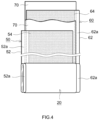
- a lithium ion secondary battery 100 illustrated in FIG. 3 is a sealed battery in which a flat wound electrode body 20 and a nonaqueous electrolyte (not shown) are housed in a flat square battery case (i.e., an outer container) 30.
- the battery case 30 includes a positive electrode terminal 42 and a negative electrode terminal 44 for external connection, and a thin safety valve 36 configured to release the internal pressure when the internal pressure of the battery case 30 increases to a predetermined level or more.
- the positive and negative electrode terminals 42 and 44 are electrically connected to positive and negative electrode current collector plates 42a and 44a, respectively.
- a material for the battery case 30 is, for example, a metal material that is lightweight and has high thermal conductivity, such as aluminium.
- a positive electrode sheet 50 and a negative electrode sheet 60 are stacked with two long separator sheets 70 interposed therebetween and wound in the longitudinal direction.
- a positive electrode active material layer 54 is formed on one or each (each in this example) surface of an elongated positive electrode current collector 52 along the longitudinal direction.
- a negative electrode active material layer 64 is formed on one or each (each in this example) surface of an elongated negative electrode current collector 62 along the longitudinal direction.
- a positive electrode active material layer non-formed portion 52a i.e., a portion where no positive electrode active material layer 54 is formed and the positive electrode current collector 52 is exposed
- a negative electrode active material layer non-formed portion 62a i.e., a portion where no negative electrode active material layer 64 is formed and the negative electrode current collector 62 is exposed
- a positive electrode current collector plate 42a and a negative electrode current collector plate 44a are respectively joined to the positive electrode active material layer non-formed portion 52a and the negative electrode active material layer non-formed portion 62a.
- the positive electrode current collector 52 a known positive electrode current collector for use in a lithium ion secondary battery may be used, and examples of the positive electrode current collector 52 include sheets or foil of highly conductive metals (e.g., aluminium, nickel, titanium, and stainless steel).
- the positive electrode current collector 52 is desirably aluminium foil.
- the positive electrode current collector 52 are not specifically limited, and may be appropriately determined depending on battery design.
- the thickness thereof is not specifically limited, and is, for example, 5 ⁇ m or more and 35 ⁇ m or less, and desirably 7 ⁇ m or more and 20 ⁇ m or less.
- the positive electrode active material layer 54 includes a positive electrode active material.
- the positive electrode active material include: lithium transition metal composite oxides such as lithium nickel composite oxide (e.g., LiNiO 2 ), lithium cobalt composite oxide (e.g., LiCoO 2 ), lithium nickel cobalt manganese composite oxide (e.g., LiNi 1/3 Co 1/3 Mn 1/3 O 2 ), lithium nickel cobalt aluminium composite oxide (e.g., LiNi 0.8 Co 0.15 Al 0.5 O 2 ), lithium manganese composite oxide (e.g., LiMn 2 O 4 ), and lithium nickel manganese composite oxide (e.g., LiNi 0.5 Mn 1.5 O 4 ); and lithium transition metal phosphate compounds (e.g., LiFePO 4 ).
- lithium nickel composite oxide e.g., LiNiO 2
- LiCoO 2 lithium cobalt composite oxide
- LiNi 1/3 Co 1/3 Mn 1/3 O 2 lithium nickel cobalt aluminium composite oxide
- the positive electrode active material layer 54 may include components other than the positive electrode active material, such as trilithium phosphate, a conductive material, and a binder.
- a conductive material include carbon black such as acetylene black (AB) and other carbon materials (e.g., graphite).
- the binder include polyvinylidene fluoride (PVDF).
- the content of the positive electrode active material in the positive electrode active material layer 54 is not specifically limited, and is desirably 70 mass% or more, more desirably 80 mass% or more, and even more desirably 85 mass% or more and 99 mass% or less.
- the content of trilithium phosphate in the positive electrode active material layer 54 is not specifically limited, and is desirably 0.1 mass% or more and 15 mass% or less, and more desirably 0.2 mass% or more and 10 mass% or less.
- the content of the conductive material in the positive electrode active material layer 54 is not specifically limited, and is desirably 0.1 mass% or more and 20 mass% or less, and more desirably 0.3 mass% or more and 15 mass% or less.
- the content of the binder in the positive electrode active material layer 54 is not specifically limited, and is desirably 0.4 mass% or more and 15 mass% or less, and more desirably 0.5 mass% or more and 10 mass% or less.
- the thickness of the positive electrode active material layer 54 is not specifically limited, and is, for example, 10 ⁇ m or more and 300 ⁇ m or less, and desirably 20 ⁇ m or more and 200 ⁇ m or less.
- the negative electrode current collector 62 a known negative electrode current collector for use in a lithium ion secondary battery may be used, and examples of the negative electrode current collector include sheets or foil of highly conductive metals (e.g., copper, nickel, titanium, and stainless steel).
- the negative electrode current collector 62 is desirably copper foil.
- the thickness thereof is not specifically limited, and is, for example, 5 ⁇ m or more and 35 ⁇ m or less, and is desirably 6 ⁇ m or more and 20 ⁇ m or less.
- the negative electrode active material layer 64 includes, as a negative electrode active material, the negative electrode active material according to the embodiment described above.
- the negative electrode active material layer 64 may include another negative electrode active material in addition to the negative electrode active material according to the above embodiment within a range that does not significantly inhibit the effects of the present disclosure.
- the negative electrode active material layer 64 can include components other than the active material, such as a binder or a thickener.
- a binder examples include styrene-butadiene rubber (SBR) and polyvinylidene fluoride (PVDF).
- PVDF polyvinylidene fluoride
- the thickener examples include carboxymethyl cellulose (CMC).
- the content of the negative electrode active material in the negative electrode active material layer 64 is desirably 90 mass% or more, and more desirably 95 mass% or more and 99 mass% or less.
- the content of the binder in the negative electrode active material layer 64 is desirably 0.1 mass% or more and 8 mass% or less, and more desirably 0.5 mass% or more and 3 mass% or less.
- the content of the thickener in the negative electrode active material layer 64 is desirably 0.3 mass% or more and 3 mass% or less, and more desirably 0.5 mass% or more and 2 mass% or less.
- the thickness of the negative electrode active material layer 64 is not specifically limited, and is, for example, 10 ⁇ m or more and 300 ⁇ m or less, and desirably 20 ⁇ m or more and 200 ⁇ m or less.
- the separator 70 examples include a porous sheet (film) of a resin such as polyethylene (PE), polypropylene (PP), polyester, cellulose, and polyamide.
- the porous sheet may have a single-layer structure or a laminated structure of two or more layers (e.g., three-layer structure in which PP layers are stacked on both surfaces of a PE layer).
- a heat-resistance layer (HRL) may be provided on a surface of the separator 70.
- the thickness of the separator 70 is not specifically limited, and is, for example, 5 ⁇ m or more and 50 ⁇ m or less, and is desirably 10 ⁇ m or more and 30 ⁇ m or less.
- a nonaqueous electrolyte typically includes a nonaqueous solvent and a supporting electrolyte (electrolyte salt).
- a nonaqueous solvent various organic solvents such as carbonates, ethers, esters, nitriles, sulfones, and lactones for use in an electrolyte of a typical lithium ion secondary battery can be used without any particular limitation.
- carbonates are desirable, and specific examples of the carbonates include ethylene carbonate (EC), propylene carbonate (PC), diethyl carbonate (DEC), dimethyl carbonate (DMC), ethyl methyl carbonate (EMC), monofluoroethylene carbonate (MFEC), difluoroethylene carbonate (DFEC), monofluoromethyl difluoromethyl carbonate (F-DMC), and trifluorodimethyl carbonate (TFDMC).
- EC ethylene carbonate
- PC propylene carbonate
- DEC diethyl carbonate
- DMC dimethyl carbonate
- EMC ethyl methyl carbonate
- EMC ethyl methyl carbonate
- MFEC monofluoroethylene carbonate
- DFEC difluoroethylene carbonate
- F-DMC monofluoromethyl difluoromethyl carbonate
- TFDMC trifluorodimethyl carbonate
- Such nonaqueous solvents may be used alone or two or more of them may be used in combination.
- the supporting electrolyte include lithium salts (desirably LiPF 6 ) such as LiPF 6 , LiBF 4 , and lithium bis(fluorosulfonyl)imide (LiFSI).
- LiPF 6 lithium salts
- LiBF 4 lithium bis(fluorosulfonyl)imide
- the concentration of the supporting electrolyte is desirable 0.7 mol/L or more and 1.3 mol/L or less.
- the nonaqueous electrolyte may include components not described above, for example, various additives exemplified by: a film forming agent such as vinylene carbonate (VC) and an oxalato complex; a gas generating agent such as biphenyl (BP) or cyclohexylbenzene (CHB); and a thickener, to the extent that the effects of the present disclosure are not significantly impaired.
- a film forming agent such as vinylene carbonate (VC) and an oxalato complex
- a gas generating agent such as biphenyl (BP) or cyclohexylbenzene (CHB)
- BP biphenyl
- CHB cyclohexylbenzene
- the lithium ion secondary battery 100 is applicable to various applications. Desired examples of application include driving power supplies to be mounted on vehicles such as electric vehicles (BEVs), hybrid electric vehicles (HEVs), and plug-in hybrid electric vehicles (PHEVs).
- BEVs electric vehicles
- HEVs hybrid electric vehicles
- PHEVs plug-in hybrid electric vehicles
- the lithium ion secondary battery 100 can also be used as a storage battery for a small-size power storage device and the like.
- the lithium ion secondary battery 100 can also be used in a form of a battery pack in which a plurality of batteries are typically connected in series and/or in parallel.
- the lithium ion secondary battery 100 including the flat wound electrode body 20 can also be configured as a lithium ion secondary battery including a stacked-type electrode body (i.e., electrode body in which a plurality of positive electrodes and a plurality of negative electrodes are alternately stacked).
- the lithium ion secondary battery may be configured as a cylindrical lithium ion secondary battery, a laminate-cased lithium ion secondary battery, or other types of batteries.
- the lithium ion secondary battery may also be configured as an all-solid-state lithium ion secondary battery using a solid electrolyte instead of a nonaqueous electrolyte according to a known method.
- the negative electrode active material according to the embodiment described above is suitable as a negative electrode active material of a lithium ion secondary battery, but is also usable as a negative electrode active material of other secondary batteries.
- the other secondary batteries can be configured according to a known method.
- the secondary battery according to this embodiment can be configured as a secondary battery other than a lithium ion secondary battery according to a known method.
- Petroleum-based cokes having different sulfur concentrations were prepared. Each petroleum-based coke was roughly pulverized to have a particle size of 10 mm or less with a hammer mill, and then further pulverized with a jet mill. The resulting pulverized material was classified with an airflow classifier, and thereby submicron-order fine powder generated by the pulverization was removed. In this manner, a graphite precursor was prepared. Table 1 shows the sulfur concentration of the graphite precursor. It should be noted that the sulfur concentration was measured by a method described later.
- graphite precursor As a graphite precursor, the same graphite precursor as that used in Example 3 was used. About 20 g of the graphite precursor was put into a carbon crucible, and was placed in an Acheson furnace. The atmosphere in this furnace was an argon atmosphere. Then, graphitization was performed such that the graphite precursor was heated to 3000°C at a temperature rise rate of about 30°C/hour, and held at about 3000°C for four days. Thus, in this heating, about four days were needed for a temperature rise to 2800°C or more. Thereafter, heating was stopped, and graphitized substance was allowed to cool in the furnace. In this manner, artificial graphite particles (i.e., negative electrode active material) of Comparative Example 2 were obtained.
- artificial graphite particles i.e., negative electrode active material
- a total organic halogen analyzer "TOX-100" manufactured by Mitsubishi Chemical Corporation was used as combustion equipment of a graphite precursor.
- a sample in which 5 mg of the graphite precursor used in each of the examples and the comparative examples and 50 mg of a tungsten-based combustion improver were mixed was collected on a sample board (ceramic board). The sample was burnt under an oxygen airflow with the equipment described above. The heater temperature was 1100°C, and the heating time was 500 seconds.
- a sulfur component in the generated combustion gas was collected in 20 mL of an absorbing solution. It should be noted that the absorbing solution was prepared by adding a hydrogen peroxide solution to deionized water such that the concentration of the hydrogen peroxide was 5 ⁇ g/mL.
- This slurry was applied onto a surface of copper foil with a thickness of 10 ⁇ m and dried, and then roll-pressed, thereby preparing a negative electrode sheet. A thickness of the negative electrode sheet at this state was measured.
- metallic lithium foil As a lithium electrode, metallic lithium foil was prepared.
- HRL ceramic particle layer
- LiPF 6 as a supporting electrolyte was dissolved at a concentration of 1.0 mol/L, thereby preparing a nonaqueous electrolyte.
- the negative electrode sheet, the separator, and the metallic lithium foil were stacked. At this time, the HRL of the separator faced the negative electrode sheet.
- the resulting stacked body was housed and sealed in a battery case together with the nonaqueous electrolyte, thereby preparing coin half cell.
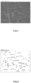
- the thus-produced negative electrode active material layer of the negative electrode was subjected to ion milling so that a cross section of the layer was exposed.
- the cross section was observed with a commercially available scanning electron microscope (SEM), and an SEM image was obtained.
- SEM scanning electron microscope
- FIGS. 5 and 6 a cross-sectional SEM images of the artificial graphite particles of Example 3 and Comparative Example 2 are shown in FIGS. 5 and 6 , respectively.
- Each of the evaluation half cells was subjected to constant-current charging to 3 V vs. Li electrode with a current value of 0.1 C and then subjected to constant-voltage charging to a current value of 1/10 C. Thereafter, each evaluation half cell was subjected to constant-current discharging to 1.6 V vs. Li electrode with a current value of 0.1 C and then subjected to constant-voltage discharging to a current value of 1/10 C.
- This charging/discharging cycle was repeated twice, and a discharge capacity (mAh) at the discharge in the second cycle was determined. From this discharge capacity and the weight of the negative electrode active material, a capacity density (mAh/g) of the negative electrode active material was calculated. Table 1 shows the results.
- the thickness of the negative electrode sheet at fabrication measured as described above was defined as an initial thickness of the negative electrode.
- Each evaluation half cell was charged to a capacity value of 80% of the discharge capacity measured as described above. Thereafter, each evaluation half cell was disassembled, and the thickness of the negative electrode was measured and defined as the thickness of the negative electrode after charging.
- An expansion rate was determined by the equation below. Table 1 shows the results.
- Expansion rate % thickness of negative electrode after charging/initial thickness of negative electrode ⁇ 100 [Table 1] Table 1 Precursor Graphitized Artificial graphite particles Evaluation Sulfur concentration (%) Temperature rise rate Particle size ( ⁇ m) I G /I D ratio Interplanar distance d 002 ( ⁇ ) Presence /absence of internal voids Porosity (%) Average circularity Capacity density (mAh/g) Expansion rate (%) Example 1 0.4 50°C/min. 7.0 58.8 3.362 present 0.7 0.15 322 113 Example 2 0.5 50°C/min. 7.2 35.7 3.366 present 3.6 0.31 321 110 Example 3 0.9 50°C/min.
- Example 5 5.5 50°C/min. 9.1 5.8 3.371 present 10.4 0.53 318 104
- Example 6 7.0 50°C/min. 10.1 1.7 3.379 present 15.0 0.58 317 103 Comparative Example 1 0.3 50°C/min. 6.9 59.0 3.362 absent - - 317 119 Comparative Example 2 0.9 30°C/hour 7.0 38.5 3.369 absent - - 311 120
Landscapes
- Chemical & Material Sciences (AREA)
- Organic Chemistry (AREA)
- Inorganic Chemistry (AREA)
- Chemical Kinetics & Catalysis (AREA)
- Electrochemistry (AREA)
- General Chemical & Material Sciences (AREA)
- Engineering & Computer Science (AREA)
- Geology (AREA)
- General Life Sciences & Earth Sciences (AREA)
- Life Sciences & Earth Sciences (AREA)
- Materials Engineering (AREA)
- Manufacturing & Machinery (AREA)
- Battery Electrode And Active Subsutance (AREA)
Applications Claiming Priority (1)
| Application Number | Priority Date | Filing Date | Title |
|---|---|---|---|
| JP2022072357A JP7583762B2 (ja) | 2022-04-26 | 2022-04-26 | 負極活物質、二次電池および人造黒鉛粒子の製造方法 |
Publications (1)
| Publication Number | Publication Date |
|---|---|
| EP4269338A1 true EP4269338A1 (fr) | 2023-11-01 |
Family
ID=86052123
Family Applications (1)
| Application Number | Title | Priority Date | Filing Date |
|---|---|---|---|
| EP23168001.8A Pending EP4269338A1 (fr) | 2022-04-26 | 2023-04-14 | Matériau actif d'électrode négative, batterie secondaire et procédé de production de particules de graphite artificiel |
Country Status (5)
| Country | Link |
|---|---|
| US (1) | US20230387411A1 (fr) |
| EP (1) | EP4269338A1 (fr) |
| JP (1) | JP7583762B2 (fr) |
| KR (1) | KR20230151907A (fr) |
| CN (1) | CN116960326A (fr) |
Families Citing this family (1)
| Publication number | Priority date | Publication date | Assignee | Title |
|---|---|---|---|---|
| KR20260020031A (ko) | 2025-04-08 | 2026-02-10 | 재단법인 포항산업과학연구원 | 인조흑연 전구체, 인조흑연 및 이의 제조방법 |
Citations (4)
| Publication number | Priority date | Publication date | Assignee | Title |
|---|---|---|---|---|
| JPH0325336B2 (fr) | 1984-07-13 | 1991-04-05 | Aruritsuchi Jeraato Jobusuto | |
| JP4421750B2 (ja) * | 2000-08-16 | 2010-02-24 | Jfeケミカル株式会社 | 炭素材料の製造方法およびリチウムイオン二次電池 |
| KR20180083155A (ko) * | 2017-01-12 | 2018-07-20 | 한국해양대학교 산학협력단 | 탄소재를 포함하는 폐기물을 통한 인조흑연 제조방법 |
| CN115838170A (zh) * | 2022-03-03 | 2023-03-24 | 宁德时代新能源科技股份有限公司 | 改性石墨、制备方法以及包含该改性石墨的二次电池和用电装置 |
Family Cites Families (4)
| Publication number | Priority date | Publication date | Assignee | Title |
|---|---|---|---|---|
| JP5401631B2 (ja) | 2011-10-21 | 2014-01-29 | 昭和電工株式会社 | リチウムイオン電池用電極材料の製造方法 |
| CN118572107A (zh) * | 2014-07-07 | 2024-08-30 | 三菱化学株式会社 | 碳材料、碳材料的制造方法、以及使用了碳材料的非水系二次电池 |
| JP6625336B2 (ja) | 2015-03-26 | 2019-12-25 | 三菱ケミカル株式会社 | 非水系二次電池負極用炭素材及び非水系二次電池 |
| JP6278135B1 (ja) | 2017-02-24 | 2018-02-14 | Tdk株式会社 | 負極活物質、負極及びリチウムイオン二次電池 |
-
2022
- 2022-04-26 JP JP2022072357A patent/JP7583762B2/ja active Active
-
2023
- 2023-04-14 EP EP23168001.8A patent/EP4269338A1/fr active Pending
- 2023-04-21 KR KR1020230052544A patent/KR20230151907A/ko active Pending
- 2023-04-24 CN CN202310446655.0A patent/CN116960326A/zh active Pending
- 2023-04-25 US US18/139,064 patent/US20230387411A1/en active Pending
Patent Citations (4)
| Publication number | Priority date | Publication date | Assignee | Title |
|---|---|---|---|---|
| JPH0325336B2 (fr) | 1984-07-13 | 1991-04-05 | Aruritsuchi Jeraato Jobusuto | |
| JP4421750B2 (ja) * | 2000-08-16 | 2010-02-24 | Jfeケミカル株式会社 | 炭素材料の製造方法およびリチウムイオン二次電池 |
| KR20180083155A (ko) * | 2017-01-12 | 2018-07-20 | 한국해양대학교 산학협력단 | 탄소재를 포함하는 폐기물을 통한 인조흑연 제조방법 |
| CN115838170A (zh) * | 2022-03-03 | 2023-03-24 | 宁德时代新能源科技股份有限公司 | 改性石墨、制备方法以及包含该改性石墨的二次电池和用电装置 |
Non-Patent Citations (2)
| Title |
|---|
| FUJIMOTO K I ET AL: "Mechanism of puffing and the role of puffing inhibitors in the graphitization of electrodes from needle cokes", CARBON, ELSEVIER OXFORD, GB, vol. 27, no. 6, 1 January 1989 (1989-01-01), pages 909 - 917, XP023890932, ISSN: 0008-6223, [retrieved on 19890101], DOI: 10.1016/0008-6223(89)90041-9 * |
| SUGIMOTO Y ET AL: "The effect of sulfur evolution on the properties of high-temperature carbons-I. Thianthrene and thianthrene-anthracene precursors", CARBON, ELSEVIER OXFORD, GB, vol. 23, no. 4, 1 January 1985 (1985-01-01), pages 411 - 416, XP022803761, ISSN: 0008-6223, [retrieved on 19850101], DOI: 10.1016/0008-6223(85)90034-X * |
Also Published As
| Publication number | Publication date |
|---|---|
| JP7583762B2 (ja) | 2024-11-14 |
| JP2023161790A (ja) | 2023-11-08 |
| KR20230151907A (ko) | 2023-11-02 |
| US20230387411A1 (en) | 2023-11-30 |
| CN116960326A (zh) | 2023-10-27 |
Similar Documents
| Publication | Publication Date | Title |
|---|---|---|
| KR102838200B1 (ko) | 음극 활물질, 그의 제조방법, 2차전지 및 2차전지를 포함하는 배터리 모듈, 배터리 팩 및 디바이스 | |
| KR101738280B1 (ko) | 비수 전해질 이차 전지 | |
| KR102264739B1 (ko) | 음극 활물질 및 이의 제조 방법, 상기 음극 활물질을 포함하는 음극 및 리튬 이차전지 | |
| KR101758992B1 (ko) | 리튬 이차전지용 양극활물질, 이의 제조방법 및 이를 포함하는 리튬 이차전지 | |
| EP2980885B1 (fr) | Batterie secondaire à électrolyte non aqueux | |
| US10347946B2 (en) | Non-aqueous electrolyte secondary battery, electrode body used therefor, and method of manufacturing the electrode body | |
| KR20180014710A (ko) | 비수전해질 이차 전지용 부극 활물질, 비수전해질 이차 전지용 부극, 및 비수전해질 이차 전지, 그리고 부극 활물질 입자의 제조 방법 | |
| WO2013080379A1 (fr) | Batterie secondaire au lithium et procédé pour fabrication de celle-ci | |
| JP7443579B2 (ja) | 非水電解質電池及び電池パック | |
| US12062792B2 (en) | Negative electrode material for lithium-ion secondary cell, method for manufacturing negative electrode material for lithium-ion secondary cell, negative electrode material slurry for lithium-ion secondary cell, negative electrode for lithium-ion secondary cell, and lithium-ion secondary cell | |
| EP3127176B1 (fr) | Batterie rechargeable à électrolyte non aqueux | |
| JP7495918B2 (ja) | 正極およびこれを用いた非水電解質二次電池 | |
| EP3686160B1 (fr) | Matériau actif d'électrode positive à base de cobalt et de lithium, procédé de fabrication de ce matériau actif, électrode positive le comprenant et batterie rechargeable | |
| KR20210077487A (ko) | 음극 및 상기 음극을 포함하는 이차 전지 | |
| EP4269338A1 (fr) | Matériau actif d'électrode négative, batterie secondaire et procédé de production de particules de graphite artificiel | |
| US20230197950A1 (en) | Positive electrode active material and nonaqueous electrolyte secondary battery using the same | |
| JP7361066B2 (ja) | 黒鉛系負極活物質材料および該黒鉛系負極活物質材料の製造方法 | |
| JP7615762B2 (ja) | 電気デバイス用正極材料並びにこれを用いた全固体リチウム二次電池 | |
| JP2017130317A (ja) | 捲回電極体を有する非水電解液二次電池 | |
| EP3863093B1 (fr) | Matériau actif d'anode, son procédé de fabrication, et anode et batterie secondaire comprenant chacune celui-ci | |
| JP7542513B2 (ja) | 負極活物質及びその製造方法、並びにこれを用いたリチウムイオン二次電池 | |
| KR20230032920A (ko) | 정극 및 이것을 사용한 비수전해질 이차 전지 | |
| KR20220037985A (ko) | 음극 활물질, 이를 포함하는 음극 및 이차전지 | |
| KR102947473B1 (ko) | 리튬 이차 전지용 양극 활물질 및 이를 포함하는 리튬 이차 전지 | |
| JP7271598B2 (ja) | 非水電解液二次電池用負極および非水電解液二次電池 |
Legal Events
| Date | Code | Title | Description |
|---|---|---|---|
| PUAI | Public reference made under article 153(3) epc to a published international application that has entered the european phase |
Free format text: ORIGINAL CODE: 0009012 |
|
| STAA | Information on the status of an ep patent application or granted ep patent |
Free format text: STATUS: REQUEST FOR EXAMINATION WAS MADE |
|
| 17P | Request for examination filed |
Effective date: 20230414 |
|
| AK | Designated contracting states |
Kind code of ref document: A1 Designated state(s): AL AT BE BG CH CY CZ DE DK EE ES FI FR GB GR HR HU IE IS IT LI LT LU LV MC ME MK MT NL NO PL PT RO RS SE SI SK SM TR |