EP4269775A1 - Verfahren und vorrichtung zur erkennung von fehlzündungszylindern eines hubkolbenverbrennungsmotors unter verwendung eines torsionsschwingungssignals - Google Patents
Verfahren und vorrichtung zur erkennung von fehlzündungszylindern eines hubkolbenverbrennungsmotors unter verwendung eines torsionsschwingungssignals Download PDFInfo
- Publication number
- EP4269775A1 EP4269775A1 EP21915799.7A EP21915799A EP4269775A1 EP 4269775 A1 EP4269775 A1 EP 4269775A1 EP 21915799 A EP21915799 A EP 21915799A EP 4269775 A1 EP4269775 A1 EP 4269775A1
- Authority
- EP
- European Patent Office
- Prior art keywords
- misfiring
- torsional vibration
- fundamental frequency
- cylinder
- frequency component
- Prior art date
- Legal status (The legal status is an assumption and is not a legal conclusion. Google has not performed a legal analysis and makes no representation as to the accuracy of the status listed.)
- Pending
Links
Images




Classifications
-
- G—PHYSICS
- G01—MEASURING; TESTING
- G01M—TESTING STATIC OR DYNAMIC BALANCE OF MACHINES OR STRUCTURES; TESTING OF STRUCTURES OR APPARATUS, NOT OTHERWISE PROVIDED FOR
- G01M15/00—Testing of engines
- G01M15/04—Testing internal-combustion engines
- G01M15/05—Testing internal-combustion engines by combined monitoring of two or more different engine parameters
-
- F—MECHANICAL ENGINEERING; LIGHTING; HEATING; WEAPONS; BLASTING
- F02—COMBUSTION ENGINES; HOT-GAS OR COMBUSTION-PRODUCT ENGINE PLANTS
- F02D—CONTROLLING COMBUSTION ENGINES
- F02D41/00—Electrical control of supply of combustible mixture or its constituents
- F02D41/22—Safety or indicating devices for abnormal conditions
-
- F—MECHANICAL ENGINEERING; LIGHTING; HEATING; WEAPONS; BLASTING
- F02—COMBUSTION ENGINES; HOT-GAS OR COMBUSTION-PRODUCT ENGINE PLANTS
- F02D—CONTROLLING COMBUSTION ENGINES
- F02D41/00—Electrical control of supply of combustible mixture or its constituents
- F02D41/009—Electrical control of supply of combustible mixture or its constituents using means for generating position or synchronisation signals
-
- F—MECHANICAL ENGINEERING; LIGHTING; HEATING; WEAPONS; BLASTING
- F02—COMBUSTION ENGINES; HOT-GAS OR COMBUSTION-PRODUCT ENGINE PLANTS
- F02D—CONTROLLING COMBUSTION ENGINES
- F02D41/00—Electrical control of supply of combustible mixture or its constituents
- F02D41/02—Circuit arrangements for generating control signals
- F02D41/14—Introducing closed-loop corrections
- F02D41/1497—With detection of the mechanical response of the engine
- F02D41/1498—With detection of the mechanical response of the engine measuring engine roughness
-
- G—PHYSICS
- G01—MEASURING; TESTING
- G01M—TESTING STATIC OR DYNAMIC BALANCE OF MACHINES OR STRUCTURES; TESTING OF STRUCTURES OR APPARATUS, NOT OTHERWISE PROVIDED FOR
- G01M15/00—Testing of engines
- G01M15/04—Testing internal-combustion engines
- G01M15/11—Testing internal-combustion engines by detecting misfire
-
- F—MECHANICAL ENGINEERING; LIGHTING; HEATING; WEAPONS; BLASTING
- F02—COMBUSTION ENGINES; HOT-GAS OR COMBUSTION-PRODUCT ENGINE PLANTS
- F02D—CONTROLLING COMBUSTION ENGINES
- F02D41/00—Electrical control of supply of combustible mixture or its constituents
- F02D41/22—Safety or indicating devices for abnormal conditions
- F02D2041/228—Warning displays
-
- F—MECHANICAL ENGINEERING; LIGHTING; HEATING; WEAPONS; BLASTING
- F02—COMBUSTION ENGINES; HOT-GAS OR COMBUSTION-PRODUCT ENGINE PLANTS
- F02D—CONTROLLING COMBUSTION ENGINES
- F02D41/00—Electrical control of supply of combustible mixture or its constituents
- F02D41/24—Electrical control of supply of combustible mixture or its constituents characterised by the use of digital means
- F02D41/26—Electrical control of supply of combustible mixture or its constituents characterised by the use of digital means using computer, e.g. microprocessor
- F02D41/28—Interface circuits
- F02D2041/286—Interface circuits comprising means for signal processing
-
- F—MECHANICAL ENGINEERING; LIGHTING; HEATING; WEAPONS; BLASTING
- F02—COMBUSTION ENGINES; HOT-GAS OR COMBUSTION-PRODUCT ENGINE PLANTS
- F02D—CONTROLLING COMBUSTION ENGINES
- F02D2200/00—Input parameters for engine control
- F02D2200/02—Input parameters for engine control the parameters being related to the engine
- F02D2200/10—Parameters related to the engine output, e.g. engine torque or engine speed
- F02D2200/101—Engine speed
-
- F—MECHANICAL ENGINEERING; LIGHTING; HEATING; WEAPONS; BLASTING
- F02—COMBUSTION ENGINES; HOT-GAS OR COMBUSTION-PRODUCT ENGINE PLANTS
- F02D—CONTROLLING COMBUSTION ENGINES
- F02D2200/00—Input parameters for engine control
- F02D2200/02—Input parameters for engine control the parameters being related to the engine
- F02D2200/10—Parameters related to the engine output, e.g. engine torque or engine speed
- F02D2200/1012—Engine speed gradient
-
- F—MECHANICAL ENGINEERING; LIGHTING; HEATING; WEAPONS; BLASTING
- F02—COMBUSTION ENGINES; HOT-GAS OR COMBUSTION-PRODUCT ENGINE PLANTS
- F02D—CONTROLLING COMBUSTION ENGINES
- F02D2200/00—Input parameters for engine control
- F02D2200/02—Input parameters for engine control the parameters being related to the engine
- F02D2200/10—Parameters related to the engine output, e.g. engine torque or engine speed
- F02D2200/1015—Engines misfires
-
- Y—GENERAL TAGGING OF NEW TECHNOLOGICAL DEVELOPMENTS; GENERAL TAGGING OF CROSS-SECTIONAL TECHNOLOGIES SPANNING OVER SEVERAL SECTIONS OF THE IPC; TECHNICAL SUBJECTS COVERED BY FORMER USPC CROSS-REFERENCE ART COLLECTIONS [XRACs] AND DIGESTS
- Y02—TECHNOLOGIES OR APPLICATIONS FOR MITIGATION OR ADAPTATION AGAINST CLIMATE CHANGE
- Y02T—CLIMATE CHANGE MITIGATION TECHNOLOGIES RELATED TO TRANSPORTATION
- Y02T10/00—Road transport of goods or passengers
- Y02T10/10—Internal combustion engine [ICE] based vehicles
- Y02T10/40—Engine management systems
Definitions
- the present invention relates to a method for detecting a misfiring cylinder, which is one of the main causes of malfunction in a reciprocating internal-combustion engine system used throughout industries such as ships, automobiles, power generation facilities, and petrochemicals, and more particularly, to a method and device for detecting in real time whether a cylinder is misfiring and a position of a misfiring cylinder using the amplitude and phase of a fundamental frequency component obtained by frequency analysis of a torsional vibration signal of a reciprocating internal-combustion engine system.
- a misfiring phenomenon in which combustion does not occur in a specific cylinder during operation often occurs.
- the misfiring is recently more likely to increase due to the use of low-quality oil or the like due to the rise in oil prices.
- the misfiring occurs, not only environmental pollution due to the increase in harmful emissions due to incomplete combustion, but also fatal malfunctions such as deterioration in operation performance and stoppage of operation due to damage to shafting elements may occur. Therefore, when cylinder misfiring occurs in a reciprocating internal combustion engine, which is mostly a cylinder engine, the demand for malfunction diagnosis and saving maintenance cost and time is increasing day by day.
- a method for monitoring pressure or temperature of a cylinder To detect the misfiring cylinder, a method for monitoring pressure or temperature of a cylinder, a method for measuring temperature of exhaust gas, and a method for using a vibration signal or a torsional vibration signal, and the like have been used.
- these methods have limitations in general application to internal combustion engine systems due to problems such as lifetime and cost of sensors exposed to the combustion environment, and difficulty in obtaining information on which cylinder the misfiring has occurred even if the misfiring can be diagnosed, and the like.
- automotive internal combustion engines are standardized and mass-produced, these methods are applied to the automotive internal combustion engines that can be patterned and statistically applied.
- a "method and device for detecting misfiring in an internal combustion engine" using a torsional vibration signal disclosed in the related art document is a method for determining a cylinder at a position corresponding to a peak value of a signal filtered through a band pass filter as a misfiring cylinder, which may give inaccurate results when the peak value is at a boundary of a segmentation section.
- the present invention is to solve the problems of the related art, and an object of the present invention is to determine whether misfiring has occurred by applying amplitude and phase characteristics of fundamental frequency components obtained by frequency analysis of a torsional vibration signal and improve malfunction diagnosis and maintenance functions of a reciprocating internal-combustion engine system by accurately detecting a position of a misfiring cylinder.
- a method includes: acquiring a torsional vibration signal by using a sensor for measuring a rotational speed installed to coincide with a position of a top dead center of a reference cylinder (usually cylinder No.
- FIG. 1 illustrates an example of a misfiring cylinder detected by measuring a torsional vibration signal, performing frequency analysis on the torsional vibration signal through signal processing, and then performing application processing on the torsional vibration signal.
- a general sensor may be used to measure the torsional vibration signal, and a sensor 1 for measuring a rotational speed at an arbitrary position where measurement is easy is installed to coincide with a position of a top dead center of a reference cylinder (usually cylinder No. 1), and a sensor 2 for measuring a change in a rotational angular velocity is installed to detect a section obtained by dividing one rotational angle of a crankshaft into equal intervals in the form of a pulse signal.
- the torsional vibration signal detection unit 3 acquires the torsional vibration signal using these pulse signals.
- torsional vibration excitation force is first evaluated when the misfiring occurs in a reciprocating internal-combustion engine which is mostly a multi-cylinder engine.
- the torsional vibration excitation force is the excitation force caused by the rotational torque acting on the crankshaft according to a series of explosion orders during one cycle.
- the torsional vibration excitation force F(t) of an inline and V-type reciprocating internal-combustion engine may be expressed as the sum of the fundamental frequency and harmonic components as follows:
- the amplitude F 0,i (k) and phase ⁇ i (k) of the torsional vibration excitation force component may be easily obtained using cylinder pressure diagrams or torque harmonic coefficients provided by engine manufacturers or classification societies for torsional vibration analysis or the like.
- the torsional vibration signal x(t) measured by the torsional vibration signal detection unit 3 may also be expressed as the sum of the fundamental frequency and harmonic components.
- x t ⁇ k n X 0 k e j k ⁇ t + ⁇ k
- X 0 (k) amplitude of k-order component of torsional vibration signal
- ⁇ (k) phase of k-order component of torsional vibration signal
- torsional vibration signal x(t) may be represented in the form of a digitized pulse signal.
- the signal processing unit 4 performs frequency analysis such as Fast Fourier Transform (FFT) on the torsional vibration signal to obtain the amplitude X 0 (k) and phase ⁇ (k) of the angle displacement corresponding to the k-order difference component.
- FFT Fast Fourier Transform
- the application processing unit 5 uses the X 0 (k) and phase ⁇ (k) of the fundamental frequency component obtained from the signal processing unit 4 to perform the misfiring cylinder detection process described below.
- the fundamental frequency and harmonic components of the torsional vibration signal x(t) may be expressed as the following sine function by taking an imaginary part of the above Equation.
- x k t X 0 k sin k ⁇ i x dx + ⁇ k
- the order component is applied to a 2-stroke engine and a 4-stroke engine as follows, considering the rotation of the crankshaft during one cycle.
- k 0.5, 1.0, 1.5,..., n (4-stroke engine)
- the 4-stroke engine in which two rotations of the crankshaft are one cycle is the fundamental frequency component for detecting the misfiring cylinder.
- the order component k shown below is called the value representing the fundamental frequency component.
- the contribution of the fundamental frequency component to both the excitation force and the torsional vibration response is very low.
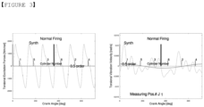
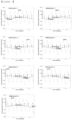
- the excitation force of the fundamental frequency component increases as illustrated in FIG. 4
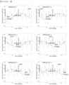
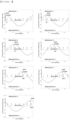
- the resulting torsional vibration response has the greatest contribution of the fundamental frequency component in the torsional vibration signal as illustrated in FIG. 5 . Therefore, when the amplitude of the fundamental frequency component exceeds a certain percentage of the torsional vibration signal amplitude, it may be determined that the misfiring cylinder has occurred.
- the pulse signal of the rotational speed sensor that coincides with a pulse signal of a camshaft position sensor usually installed in the 4-stroke engine is identified as the pulse signal indicating the top dead center of the reference cylinder.
- the crank angle i max dx at which the fundamental frequency component of the torsional vibration signal x k (t) expressed as the sine function has the maximum value is expressed as in Equation 1, with the top dead center of the reference cylinder corresponding to the identified rotational speed pulse signal as the origin of the angle displacement.
- i xmax dx 1 k ⁇ 2 ⁇ ⁇ k
- the misfiring cylinder is a cylinder in which an explosion stroke occurs at positions where the excitation force of the fundamental frequency component has the minimum value, and at these positions, the vibration response of the fundamental frequency component has the maximum value, so at these positions, the misfiring cylinder may be specified by obtaining the crank angle displacement.
- i Fmin dx 1 k 3 ⁇ 2 ⁇ ⁇ k + FA i
- Equation 2 that can easily specify the position of the misfiring cylinder can be derived.
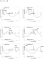
- the torsional vibration response characteristics according to the change in the torsional vibration measurement position are illustrated in FIG. 6 .
- the amplitude and phase of the torsional vibration fundamental frequency component show characteristics regardless of the measurement position, so it can be seen that the method of the present invention may be effectively used in the industrial field.
- the result of the application processing unit 5 described above is displayed on the display device 7 through the transmission unit 6 or transmitted for other purposes.
- the present invention it is possible to effectively detect whether a reciprocating internal-combustion engine system operated in an industrial field is misfiring and a position of a misfiring cylinder.
- a misfiring cylinder detection method for a reciprocating internal-combustion engine using a torsional vibration signal includes:
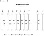
- FIGS. 4 and 5 illustrate torsional vibration excitation force and vibration response during misfiring of each cylinder in Case 1 of 4-stroke inline internal combustion engine generator in Table 1.
- a torsional vibration synthesis response (Synth) graph is a torsional vibration signal x(t) detected by the torsional vibration detection unit 3 in FIG. 1 , and the signal processing unit 4 extracts an amplitude X 0 (k) and a phase ⁇ (k) of a fundamental frequency component through frequency analysis, and obtains the fundamental frequency component (0.5 order) graph in FIG. 5 .
- the application processing unit 5 in FIG. 1 determines that the misfiring cylinder has occurred when the amplitude X 0 (k) of the fundamental frequency component (0.5 order) in FIG. 5 is greater than a certain level compared to the synthesized amplitude (Synth). When it is determined that the misfiring has occurred, for the 4-stroke internal combustion engine system, as additionally illustrated in FIG.
- a preceding pulse signal which is the current rotational speed pulse
- a following pulse is identified as a pulse indicating the top dead center of the reference cylinder
- the top dead center of the identified reference cylinder is corrected to an origin of crank angle displacement to recalculate the phase ⁇ (k) of the fundamental frequency component (0.5 order) and a crank angle i xmax dx at a maximum value.
- the present invention relates to a method for detecting a misfiring cylinder, which is one of the main causes of malfunction in an internal combustion engine system such as ships, automobiles, power generation facilities, and petrochemicals, and more particularly, to a method and device for detecting whether a cylinder is misfiring and a position of a misfiring cylinder by frequency analysis of a torsional vibration signal of a reciprocating internal-combustion engine system.
- a misfiring cylinder detection device is configured to include a detection unit (3) for measuring a torsional vibration signal; a signal processing unit (4) for frequency analysis of the measured torsional vibration signal and extracting an amplitude and a phase of a fundamental frequency component; and an application processing unit (5) for determining whether misfiring has occurred using the extracted amplitude and phase and specifying the misfiring cylinder, thereby effectively detecting the misfiring and its position using the torsional vibration signal which is easy to measure.
- a detection unit (3) for measuring a torsional vibration signal
- a signal processing unit (4) for frequency analysis of the measured torsional vibration signal and extracting an amplitude and a phase of a fundamental frequency component
- an application processing unit (5) for determining whether misfiring has occurred using the extracted amplitude and phase and specifying the misfiring cylinder, thereby effectively detecting the misfiring and its position using the torsional vibration signal which is easy to measure.
- the present invention has industrial applicability because it has not only sufficient possibility of commercialization or business, but also realistically and clearly practicable.
Landscapes
- Engineering & Computer Science (AREA)
- Chemical & Material Sciences (AREA)
- Combustion & Propulsion (AREA)
- Mechanical Engineering (AREA)
- General Engineering & Computer Science (AREA)
- Physics & Mathematics (AREA)
- General Physics & Mathematics (AREA)
- Combined Controls Of Internal Combustion Engines (AREA)
- Testing Of Engines (AREA)
Applications Claiming Priority (2)
| Application Number | Priority Date | Filing Date | Title |
|---|---|---|---|
| KR1020200184079A KR102408522B1 (ko) | 2020-12-28 | 2020-12-28 | 비틀림진동 신호를 이용한 왕복동 내연기관의 착화실패 실린더 검출 방법 및 그 장치 |
| PCT/KR2021/020096 WO2022146001A1 (ko) | 2020-12-28 | 2021-12-28 | 비틀림진동 신호를 이용한 왕복동 내연기관의 착화실패 실린더 검출 방법 및 그 장치 |
Publications (2)
| Publication Number | Publication Date |
|---|---|
| EP4269775A1 true EP4269775A1 (de) | 2023-11-01 |
| EP4269775A4 EP4269775A4 (de) | 2024-12-04 |
Family
ID=74127058
Family Applications (1)
| Application Number | Title | Priority Date | Filing Date |
|---|---|---|---|
| EP21915799.7A Pending EP4269775A4 (de) | 2020-12-28 | 2021-12-28 | Verfahren und vorrichtung zur erkennung von fehlzündungszylindern eines hubkolbenverbrennungsmotors unter verwendung eines torsionsschwingungssignals |
Country Status (4)
| Country | Link |
|---|---|
| US (1) | US12436064B2 (de) |
| EP (1) | EP4269775A4 (de) |
| KR (1) | KR102408522B1 (de) |
| WO (1) | WO2022146001A1 (de) |
Families Citing this family (2)
| Publication number | Priority date | Publication date | Assignee | Title |
|---|---|---|---|---|
| KR102408522B1 (ko) * | 2020-12-28 | 2022-06-14 | 주식회사 이온씨 | 비틀림진동 신호를 이용한 왕복동 내연기관의 착화실패 실린더 검출 방법 및 그 장치 |
| CN115270435A (zh) * | 2022-07-13 | 2022-11-01 | 厦门大学 | 一种考虑喷油提前角耦合作用的内燃机轴系扭振计算方法 |
Family Cites Families (10)
| Publication number | Priority date | Publication date | Assignee | Title |
|---|---|---|---|---|
| JP3063007B2 (ja) * | 1990-03-23 | 2000-07-12 | 株式会社ユニシアジェックス | 内燃機関の失火診断装置 |
| US5269178A (en) * | 1990-12-10 | 1993-12-14 | Sensortech, L.P. | Engine misfire, knock of roughness detection method and apparatus |
| US5379634A (en) * | 1991-07-12 | 1995-01-10 | Honda Giken Kogyo Kabushiki Kaisha | Misfire-detecting system for internal combustion engines |
| JP2666232B2 (ja) * | 1992-09-17 | 1997-10-22 | 本田技研工業株式会社 | 内燃エンジンの燃焼状態検出装置 |
| KR100749667B1 (ko) * | 2006-07-06 | 2007-08-14 | 현대중공업 주식회사 | 크랭크축 속도 변화를 이용한 엔진 상태진단 시스템 및 그방법 |
| KR101180410B1 (ko) | 2010-05-04 | 2012-09-10 | 에스티엑스엔진 주식회사 | 내연기관의 실화 검출방법 및 그 장치 |
| JP5844162B2 (ja) * | 2011-03-09 | 2016-01-13 | 本田技研工業株式会社 | 内燃機関の失火検出装置 |
| JP6025640B2 (ja) * | 2013-03-28 | 2016-11-16 | 三菱重工業株式会社 | エンジンの失火時負荷制御方法およびその失火時負荷制御システム |
| JP6575550B2 (ja) * | 2017-03-23 | 2019-09-18 | トヨタ自動車株式会社 | 内燃機関の失火検出装置 |
| KR102408522B1 (ko) * | 2020-12-28 | 2022-06-14 | 주식회사 이온씨 | 비틀림진동 신호를 이용한 왕복동 내연기관의 착화실패 실린더 검출 방법 및 그 장치 |
-
2020
- 2020-12-28 KR KR1020200184079A patent/KR102408522B1/ko active Active
-
2021
- 2021-12-28 WO PCT/KR2021/020096 patent/WO2022146001A1/ko not_active Ceased
- 2021-12-28 US US18/269,764 patent/US12436064B2/en active Active
- 2021-12-28 EP EP21915799.7A patent/EP4269775A4/de active Pending
Also Published As
| Publication number | Publication date |
|---|---|
| WO2022146001A1 (ko) | 2022-07-07 |
| EP4269775A4 (de) | 2024-12-04 |
| KR102408522B1 (ko) | 2022-06-14 |
| US20240068909A1 (en) | 2024-02-29 |
| US12436064B2 (en) | 2025-10-07 |
| KR20210005823A (ko) | 2021-01-15 |
Similar Documents
| Publication | Publication Date | Title |
|---|---|---|
| Dykas et al. | Acoustic emission characteristics of a single cylinder diesel generator at various loads and with a failing injector | |
| Varbanets et al. | Improvement of diagnosing methods of the diesel engine functioning under operating conditions | |
| EP4269775A1 (de) | Verfahren und vorrichtung zur erkennung von fehlzündungszylindern eines hubkolbenverbrennungsmotors unter verwendung eines torsionsschwingungssignals | |
| Delvecchio et al. | On the use of cyclostationary indicators in IC engine quality control by cold tests | |
| Delvecchio et al. | Advanced signal processing tools for the vibratory surveillance of assembly faults in diesel engine cold tests | |
| Mauer | On-line cylinder fault diagnostics for internal combustion engines | |
| KR102063974B1 (ko) | 이산 푸리에 변환과 선형 성분이 제거된 엔진 속도의 변동 분석을 활용한 엔진 실화 진단 시스템 및 방법 | |
| WO2019130525A1 (ja) | エンジン異常検出装置 | |
| Grajales et al. | Combustion pressure estimation method of a spark ignited combustion engine based on vibration signal processing | |
| KR101180410B1 (ko) | 내연기관의 실화 검출방법 및 그 장치 | |
| Freestone et al. | The diagnosis of cylinder power faults in diesel engines by flywheel speed measurement | |
| Hu et al. | Multivariate statistical analysis strategy for multiple misfire detection in internal combustion engines | |
| Gawande et al. | Cylinder imbalance detection of six cylinder DI diesel engine using pressure variation | |
| Douglas et al. | On-line power estimation of large diesel engines using acoustic emission and instantaneous crankshaft angular velocity | |
| Jafari et al. | Detection of misfire in a six-cylinder diesel engine using acoustic emission signals | |
| GB2260194A (en) | Engine health monitoring system using crankshaft velocity variation measurements | |
| Muñoz et al. | Engine diagnosis method based on vibration and acoustic emission energy | |
| Liu et al. | The on-line detection of engine misfire at low speed using multiple feature fusion with fuzzy pattern recognition | |
| Grządziela et al. | High and medium speed marine diesel engines injection installation vibration diagnostics | |
| CN115901278A (zh) | 利用瞬时转速波形差值“零点”定位发动机失火缸的故障诊断方法 | |
| KR102063971B1 (ko) | 이산 푸리에 변환과 엔진 속도의 진폭 변화 분석을 활용한 엔진 실화 진단 시스템 및 방법 | |
| Azzoni et al. | Assessment of the potential of a Wiener-Hilbert filter for automatic diagnosis of spark ignition engine faults | |
| Abdo et al. | Low-Cost Vibration Monitoring System for Early Fault Detection in ICE Fuel Injection Systems | |
| Wu | The detection of incipient faults in small multi-cylinder diesel engines using multiple acoustic emission sensors | |
| KR102109673B1 (ko) | 이산 푸리에 변환과 임계값 이동을 활용한 엔진 실화 진단 시스템 및 방법 |
Legal Events
| Date | Code | Title | Description |
|---|---|---|---|
| STAA | Information on the status of an ep patent application or granted ep patent |
Free format text: STATUS: THE INTERNATIONAL PUBLICATION HAS BEEN MADE |
|
| PUAI | Public reference made under article 153(3) epc to a published international application that has entered the european phase |
Free format text: ORIGINAL CODE: 0009012 |
|
| STAA | Information on the status of an ep patent application or granted ep patent |
Free format text: STATUS: REQUEST FOR EXAMINATION WAS MADE |
|
| 17P | Request for examination filed |
Effective date: 20230727 |
|
| AK | Designated contracting states |
Kind code of ref document: A1 Designated state(s): AL AT BE BG CH CY CZ DE DK EE ES FI FR GB GR HR HU IE IS IT LI LT LU LV MC MK MT NL NO PL PT RO RS SE SI SK SM TR |
|
| DAV | Request for validation of the european patent (deleted) | ||
| DAX | Request for extension of the european patent (deleted) | ||
| A4 | Supplementary search report drawn up and despatched |
Effective date: 20241031 |
|
| RIC1 | Information provided on ipc code assigned before grant |
Ipc: F02D 41/28 20060101ALI20241025BHEP Ipc: F02D 41/14 20060101ALI20241025BHEP Ipc: F02D 41/00 20060101ALI20241025BHEP Ipc: G01M 15/11 20060101ALI20241025BHEP Ipc: F02D 41/22 20060101AFI20241025BHEP |
|
| STAA | Information on the status of an ep patent application or granted ep patent |
Free format text: STATUS: EXAMINATION IS IN PROGRESS |
|
| 17Q | First examination report despatched |
Effective date: 20251014 |
|
| GRAP | Despatch of communication of intention to grant a patent |
Free format text: ORIGINAL CODE: EPIDOSNIGR1 |
|
| STAA | Information on the status of an ep patent application or granted ep patent |
Free format text: STATUS: GRANT OF PATENT IS INTENDED |
|
| INTG | Intention to grant announced |
Effective date: 20260116 |
|
| GRAS | Grant fee paid |
Free format text: ORIGINAL CODE: EPIDOSNIGR3 |
|
| RIN1 | Information on inventor provided before grant (corrected) |
Inventor name: PARK, JEONGGEUN |