EP4269780A1 - Injecteur de bicarburant pour un moteur - Google Patents
Injecteur de bicarburant pour un moteur Download PDFInfo
- Publication number
- EP4269780A1 EP4269780A1 EP21911686.0A EP21911686A EP4269780A1 EP 4269780 A1 EP4269780 A1 EP 4269780A1 EP 21911686 A EP21911686 A EP 21911686A EP 4269780 A1 EP4269780 A1 EP 4269780A1
- Authority
- EP
- European Patent Office
- Prior art keywords
- intermediate body
- fuel injector
- communication
- groove
- return
- Prior art date
- Legal status (The legal status is an assumption and is not a legal conclusion. Google has not performed a legal analysis and makes no representation as to the accuracy of the status listed.)
- Pending
Links
Images



Classifications
-
- F—MECHANICAL ENGINEERING; LIGHTING; HEATING; WEAPONS; BLASTING
- F02—COMBUSTION ENGINES; HOT-GAS OR COMBUSTION-PRODUCT ENGINE PLANTS
- F02D—CONTROLLING COMBUSTION ENGINES
- F02D19/00—Controlling engines characterised by their use of non-liquid fuels, pluralities of fuels, or non-fuel substances added to the combustible mixtures
- F02D19/06—Controlling engines characterised by their use of non-liquid fuels, pluralities of fuels, or non-fuel substances added to the combustible mixtures peculiar to engines working with pluralities of fuels, e.g. alternatively with light and heavy fuel oil, other than engines indifferent to the fuel consumed
- F02D19/0663—Details on the fuel supply system, e.g. tanks, valves, pipes, pumps, rails, injectors or mixers
- F02D19/0686—Injectors
- F02D19/0694—Injectors operating with a plurality of fuels
-
- F—MECHANICAL ENGINEERING; LIGHTING; HEATING; WEAPONS; BLASTING
- F02—COMBUSTION ENGINES; HOT-GAS OR COMBUSTION-PRODUCT ENGINE PLANTS
- F02M—SUPPLYING COMBUSTION ENGINES IN GENERAL WITH COMBUSTIBLE MIXTURES OR CONSTITUENTS THEREOF
- F02M43/00—Fuel-injection apparatus operating simultaneously on two or more fuels, or on a liquid fuel and another liquid, e.g. the other liquid being an anti-knock additive
- F02M43/04—Injectors peculiar thereto
-
- F—MECHANICAL ENGINEERING; LIGHTING; HEATING; WEAPONS; BLASTING
- F02—COMBUSTION ENGINES; HOT-GAS OR COMBUSTION-PRODUCT ENGINE PLANTS
- F02M—SUPPLYING COMBUSTION ENGINES IN GENERAL WITH COMBUSTIBLE MIXTURES OR CONSTITUENTS THEREOF
- F02M45/00—Fuel-injection apparatus characterised by having a cyclic delivery of specific time/pressure or time/quantity relationship
- F02M45/02—Fuel-injection apparatus characterised by having a cyclic delivery of specific time/pressure or time/quantity relationship with each cyclic delivery being separated into two or more parts
- F02M45/04—Fuel-injection apparatus characterised by having a cyclic delivery of specific time/pressure or time/quantity relationship with each cyclic delivery being separated into two or more parts with a small initial part, e.g. initial part for partial load and initial and main part for full load
- F02M45/08—Injectors peculiar thereto
- F02M45/086—Having more than one injection-valve controlling discharge orifices
-
- F—MECHANICAL ENGINEERING; LIGHTING; HEATING; WEAPONS; BLASTING
- F02—COMBUSTION ENGINES; HOT-GAS OR COMBUSTION-PRODUCT ENGINE PLANTS
- F02M—SUPPLYING COMBUSTION ENGINES IN GENERAL WITH COMBUSTIBLE MIXTURES OR CONSTITUENTS THEREOF
- F02M47/00—Fuel-injection apparatus operated cyclically with fuel-injection valves actuated by fluid pressure
- F02M47/02—Fuel-injection apparatus operated cyclically with fuel-injection valves actuated by fluid pressure of accumulator-injector type, i.e. having fuel pressure of accumulator tending to open, and fuel pressure in other chamber tending to close, injection valves and having means for periodically releasing that closing pressure
- F02M47/027—Electrically actuated valves draining the chamber to release the closing pressure
-
- F—MECHANICAL ENGINEERING; LIGHTING; HEATING; WEAPONS; BLASTING
- F02—COMBUSTION ENGINES; HOT-GAS OR COMBUSTION-PRODUCT ENGINE PLANTS
- F02M—SUPPLYING COMBUSTION ENGINES IN GENERAL WITH COMBUSTIBLE MIXTURES OR CONSTITUENTS THEREOF
- F02M51/00—Fuel-injection apparatus characterised by being operated electrically
- F02M51/06—Injectors peculiar thereto with means directly operating the valve needle
-
- F—MECHANICAL ENGINEERING; LIGHTING; HEATING; WEAPONS; BLASTING
- F02—COMBUSTION ENGINES; HOT-GAS OR COMBUSTION-PRODUCT ENGINE PLANTS
- F02M—SUPPLYING COMBUSTION ENGINES IN GENERAL WITH COMBUSTIBLE MIXTURES OR CONSTITUENTS THEREOF
- F02M51/00—Fuel-injection apparatus characterised by being operated electrically
- F02M51/06—Injectors peculiar thereto with means directly operating the valve needle
- F02M51/061—Injectors peculiar thereto with means directly operating the valve needle using electromagnetic operating means
-
- F—MECHANICAL ENGINEERING; LIGHTING; HEATING; WEAPONS; BLASTING
- F02—COMBUSTION ENGINES; HOT-GAS OR COMBUSTION-PRODUCT ENGINE PLANTS
- F02M—SUPPLYING COMBUSTION ENGINES IN GENERAL WITH COMBUSTIBLE MIXTURES OR CONSTITUENTS THEREOF
- F02M61/00—Fuel-injectors not provided for in groups F02M39/00 - F02M57/00 or F02M67/00
- F02M61/04—Fuel-injectors not provided for in groups F02M39/00 - F02M57/00 or F02M67/00 having valves, e.g. having a plurality of valves in series
- F02M61/10—Other injectors with elongated valve bodies, i.e. of needle-valve type
-
- F—MECHANICAL ENGINEERING; LIGHTING; HEATING; WEAPONS; BLASTING
- F02—COMBUSTION ENGINES; HOT-GAS OR COMBUSTION-PRODUCT ENGINE PLANTS
- F02M—SUPPLYING COMBUSTION ENGINES IN GENERAL WITH COMBUSTIBLE MIXTURES OR CONSTITUENTS THEREOF
- F02M61/00—Fuel-injectors not provided for in groups F02M39/00 - F02M57/00 or F02M67/00
- F02M61/16—Details not provided for in, or of interest apart from, the apparatus of groups F02M61/02 - F02M61/14
- F02M61/18—Injection nozzles, e.g. having valve seats; Details of valve member seated ends, not otherwise provided for
- F02M61/1806—Injection nozzles, e.g. having valve seats; Details of valve member seated ends, not otherwise provided for characterised by the arrangement of discharge orifices, e.g. orientation or size
- F02M61/182—Discharge orifices being situated in different transversal planes with respect to valve member direction of movement
-
- F—MECHANICAL ENGINEERING; LIGHTING; HEATING; WEAPONS; BLASTING
- F02—COMBUSTION ENGINES; HOT-GAS OR COMBUSTION-PRODUCT ENGINE PLANTS
- F02M—SUPPLYING COMBUSTION ENGINES IN GENERAL WITH COMBUSTIBLE MIXTURES OR CONSTITUENTS THEREOF
- F02M61/00—Fuel-injectors not provided for in groups F02M39/00 - F02M57/00 or F02M67/00
- F02M61/16—Details not provided for in, or of interest apart from, the apparatus of groups F02M61/02 - F02M61/14
- F02M61/18—Injection nozzles, e.g. having valve seats; Details of valve member seated ends, not otherwise provided for
- F02M61/1886—Details of valve seats not covered by groups F02M61/1866 - F02M61/188
-
- F—MECHANICAL ENGINEERING; LIGHTING; HEATING; WEAPONS; BLASTING
- F02—COMBUSTION ENGINES; HOT-GAS OR COMBUSTION-PRODUCT ENGINE PLANTS
- F02M—SUPPLYING COMBUSTION ENGINES IN GENERAL WITH COMBUSTIBLE MIXTURES OR CONSTITUENTS THEREOF
- F02M2200/00—Details of fuel-injection apparatus, not otherwise provided for
- F02M2200/46—Valves, e.g. injectors, with concentric valve bodies
Definitions
- This application relates to fuel injectors, and in particular to dual fuel injectors for an engine.
- Dual-fuel engines employing a conventional fuel and an alternative fuel play a positive role in optimized use of energy source and environmental control.
- a dual fuel engine such as a diesel-natural gas engine
- gaseous fuel as an alternative fuel
- the fuel injector therein cannot be used for a dual fuel engine that uses liquid fuel as an alternative fuel. Therefore, there is a need to provide a dual fuel injector for the engine for use with liquid fuel as both traditional fuel and alternative fuel, and the use of a dual fuel injector without retrofitting an engine and fuel injector mounting interface, such that the liquid replacement fuel may be effectively utilized.
- the invention provides a fuel injector for an engine.
- the fuel injector includes a main housing; an outer valve body coupled to the main housing, the outer valve body having a first fuel nozzle and a first valve seat; an intermediate body, the intermediate body being disposed linearly movable in an inner chamber of the outer valve body, the intermediate body having a second fuel nozzle and a second valve seat, the intermediate body and the outer valve body forming therebetween a first pressure chamber and a first control chamber, the first fuel nozzle being in communication with the first pressure chamber through the first valve seat; a first input channel in communication with the first pressure chamber; a first return channel in communication with the first control chamber; a needle valve, the needle valve being disposed linearly movable in an inner chamber of the intermediate body, the needle valve and the intermediate body forming therebetween a second pressure chamber and a second control chamber, the second fuel nozzle being in communication with the second pressure chamber through the second valve seat; a second input channel in communication with the second pressure chamber; a second return channel in communication with the second
- the first input channel is formed in the outer valve body and arranged along a first radial direction of the outer valve body;
- the second input channel is formed in the outer valve body and arranged along a second radial direction of the outer valve body, the second radial direction is angularly offset relative to the first radial direction along a second circumferential direction of the outer valve body about a longitudinal axis of the fuel injector.
- the fuel injector according to the present invention further comprises an annular feed groove formed between the outer valve body and the intermediate body; an annular return groove axially offset relative to the annular feed groove; and a second control chamber in communication between the annular feed groove and the annular return groove, the second input channel including a primary input section formed in the outer valve body and a secondary input section formed in the intermediate body, an outlet of the primary input section and an inlet of the secondary input section are respectively in communication with the annular feed groove, the outlet of the secondary input section is in communication with the second pressure chamber, wherein the secondary input section is arranged along a first radial direction of the outer valve body.
- a radial distance between the inlet of the secondary input section and the longitudinal axis of the fuel injector is greater than a radial distance between the outlet of the secondary input section and the longitudinal axis of the fuel injector, the outlet of the secondary input section being disposed along the longitudinal axis between the inlet of the secondary input section and the secondary fuel nozzle, such that the secondary input section is arranged obliquely relative to the longitudinal axis and is arranged converged in a direction toward the second fuel nozzle.
- the annular feed groove comprises a first inner groove formed surround an inner wall of the outer valve body; and a first outer groove surround an outer wall of the intermediate body, the first outer groove being aligned with the first inner groove along the longitudinal axis.
- the first inner groove and the first outer groove are in a fitting engagement with each other at a first segment gap between the outer valve body and the intermediate body, to form a liquid communication between the annular feed groove and the first segment gap.
- the annular return groove comprises a second inner groove formed on and surround an inner wall of the outer valve body; and a second outer groove formed on and surround an outer wall of the intermediate body, the second outer groove being aligned with the first inner groove along the longitudinal axis.
- the second inner groove and the second outer groove are in a fitting engagement with each other at a second segment gap between the outer valve body and the intermediate body, to form a liquid communication between the annular return groove and the second segment gap.
- the second return channel is formed in the outer valve body and arranged along a third radial direction, the third radial direction is angularly offset relative to the first radial direction and the second radial direction along a third circumferential direction of the outer valve body about the longitudinal axis of the fuel injector.
- the second return channel comprises a primary return section formed in the intermediate body and a secondary return section formed in the outer valve body, an inlet of the primary return section being in communication with the second control chamber, an outlet of the primary return section and an inlet of the secondary return section are respectively in communication with the annular return groove, the primary return section and the secondary return section being arranged along the third radial direction.
- the fuel injector according to the present invention further includes a first control channel in communication with the second input channel and the first control chamber, the first control channel forming a first damping through-hole between the second input channel and the first control chamber.
- the first control channel is arranged along the third radial direction.
- the intermediate body includes a second control channel in communication with the second input channel and the second control chamber, the second control channel being arranged along the third radial direction.
- the dual fuel injector according to the present invention further includes a second damping through-hole between the second input channel and the second control chamber, wherein the second damping through-hole includes an aperture sized for providing a pressure difference between the second input channel and the second control chamber.
- the inner chamber of the intermediate body has a guiding inner surface
- the needle valve has a plurality of guiding ridges parallel to a longitudinal axis of the fuel injector, the plurality of guiding ridges being linearly movable relative to the guiding inner surface cooperatively and being distributed circumferentially
- a connection portion is formed between respective adjacent guiding ridges
- a radial gap is formed between the respective connection portions and the guiding inner surface, the radial gap forming a liquid channel.
- the guiding ridges abut against the guiding inner surface of the intermediate body.
- a portion of the needle valve corresponding to the guiding inner surface of the intermediate body comprises a prismatic segment, the prismatic segment comprising a plurality of guiding ridges distributed circumferentially and a connection portion between respective adjacent guiding ridges.
- an envelope surface of the guiding ridges forms a tight translationally movable fit with a cylindrical inner surface of the inner chamber of the intermediate body, such that the intermediate body provides guiding support to the needle valve.
- the fuel injector according to the present invention further includes a secondary housing; a first fuel inlet opening on a top portion of the secondary housing; and a second fuel inlet opening on a side wall of the main housing, the second fuel inlet being disposed between the first fuel inlet and the first fuel nozzle.
- the fuel injector according to the present invention further includes a return outlet opening on the main housing, wherein a communication between the return outlet and each of the first return channel and the second return channel is turned on or turned off controllably through a respective solenoid valve.
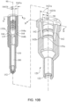
- a dual-fuel injector 100 for an engine includes a main housing 102, a secondary housing 104 connected to a side portion of the main housing 102, and a valve body disposed along a longitudinal axis 90 of the fuel injector 100 and connected to the main housing 102.
- a first fuel inlet 131 is formed on the main housing 102
- a second fuel inlet 161 is formed on the secondary housing 104.
- the fuel injector 100 also includes a first solenoid valve 191 coupled to the main housing 102 for controlling the first fuel injection, and a second solenoid valve 192 coupled to the secondary housing 104 for controlling the second fuel injection.
- the secondary housing 104 includes several mounting holes for coupling with the engine, such as bolt holes 108.
- the term “couple” refers to two or more independent components in the dual fuel injector 100 of the present invention which are directly or indirectly connected, assembled, combined or installed, including the connection, assembly, combination or installation of parts in a detachable manner between the two or more independent components, such as connection, assembly, combination or installation through threaded structure, mechanical tolerance fit structure, etc., and the two or more independent parts connected, assembled in a non-detachable manner, such as connected, assembled, combined or installed by welding, riveting, etc.
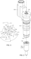
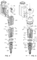
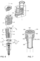
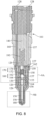
- FIGS. 3 to 10B illustrate an internal structure of the fuel injector 100 in a perspective view, a plan view, a cross-sectional view, and an exploded view, respectively, wherein FIG. 8 is a cross-sectional view of the fuel injector valve body shown in FIG. 1 in an assembled state, and the cross sections of the first, second and third radial directions located in different planes are superimposed in the same plane as shown in FIG. 4, FIG. 5 , and FIG. 6 .
- FIG. 10A is a longitudinal cross-sectional view of the valve body 106 as shown in FIG. 2 , wherein the outer valve body 120 is sectioned along the B-B direction shown in FIG. 3 , and the intermediate body 150 is sectioned along the D-D direction shown in FIG. 3 .
- the valve body 106 includes an outer valve body 120 coupled to the main housing 102, an intermediate body 150 is disposed linearly movable in an inner chamber of the outer valve body 120, and a valve core, for example, a needle valve 180, is disposed linearly movable in an inner chamber of the intermediate body 150.
- the outer valve body 120 has a first fuel nozzle 122 and a first valve seat 123.
- the intermediate body 150 has a second fuel nozzle 152 and a second valve seat 153.
- a first pressure chamber 126 and a first control chamber 129 are formed between the intermediate body 150 and the outer valve body 120.
- the first fuel nozzle 122 is in communication with the first pressure chamber 126 through the first valve seat 123.
- a second pressure chamber 156 and a second control chamber 159 are formed between the needle valve 180 and the intermediate body 150.
- the second fuel nozzle 152 is in communication with the second pressure chamber 156 through the second valve seat 153.
- the second fuel inlet 161 is disposed between the first fuel inlet 131 and the first fuel nozzle 122.
- a first elastic member, such as a first coil spring 193 is disposed in the first control chamber 129, and a second elastic member, such as a second coil spring 194 is disposed in the second control chamber 159.
- the fuel injector 100 includes a pair of first input channel 130 in communication with the first pressure chamber 126, and a first return channel 140 in communication with the first control chamber 129.
- the first input channel 130 is formed in the main housing 102 and the secondary housing 104, and is in fluid communication with the first fuel inlet 131.
- the first input channel 130 forms a fluid communication between the first pressure chamber 126 and the first fuel inlet 131.
- the first return channel 140 is formed in the main housing 102, to form a fluid communication between the first control chamber 129 and the first solenoid valve 191.
- the fuel injector 100 also includes a pair of second input channels 160 in communication with the second pressure chamber 156, and a second return channel 170 in communication with the second control chamber 159.
- a second input channel 160 is formed in the main housing 102 and in fluid communication with a second fuel inlet 161.
- the second input channel 160 forms a fluid communication between the second pressure chamber 156 and the second fuel inlet 161.
- a second return channel 170 is formed in the main housing 102 and the secondary housing 104, to form a fluid communication between the second control chamber 159 and the second solenoid valve 192.
- annular feed groove 155 and an annular return groove 158 offset relative to the annular feed groove 155 along the longitudinal axis 90 are formed between the outer valve body 120 and the intermediate body 150.
- the annular feed groove 155 includes a first inner groove 155a formed surround an inner wall of the outer valve body 120, and a first outer groove 155b formed surround the outer wall of the intermediate body 150, the first outer groove 155b is aligned with the first inner groove 155a along the longitudinal axis 90.
- the annular return groove 158 includes a second inner groove 158a formed on and surround an inner wall of the outer valve body 120, and a second outer groove 158b formed on and surround an outer wall of the intermediate body 150, the second outer groove 158b is aligned with the first inner groove 155a along the longitudinal axis 90.
- the second control chamber 159 is in communication between the annular feed groove 155 and the annular return groove 158.
- the first inner groove 155a in a fitting engagement with the first outer groove 155b to form an annular feed groove 155 for containing and transporting the liquid fuel therein.
- first inner groove 155a and the first outer groove 155b are in a fitting engagement at a first segment gap 155c disposed between the outer valve body 120 and the intermediate body 150, forming a liquid communication between the annular feed groove 155 and the first segment gap 155c, allowing the liquid fuel in the annular feed groove 155 to penetrate into the gap 155c.
- second inner groove 158a is in a fitting engagement with the second outer groove 158b to form an annular return groove 158 for containing and transporting the liquid fuel therein.
- the second inner groove 158a and the second outer groove 158b are in a fitting engagement at a second segment gap 158c disposed between the outer valve body 120 and the intermediate body 150, forming a liquid communication between the annular return groove 158 and the second segment gap 158c, allowing the liquid fuel in the annular return groove 158 to penetrate into the gap 155c.
- the liquid fuel penetrating into the gaps 155c and 158c provides lubrication between the outer valve body 120 and the intermediate body 150, assisting in a smooth linear movement of the intermediate body 150 relative to the outer valve body 120.
- the second input channel 160 includes a pair of primary input sections 162 formed in the outer valve body 120 and a pair of secondary input sections 164 formed in the intermediate body 150.
- the inlet 162a of each primary input section 162 opens on a top surface 120a of the outer valve body 120.
- the outlet 162b of each primary input section 162 and the inlet 164a of each secondary input section 164 are respectively in communication with the annular feed groove 155. As illustrated in FIG.
- a radial distance 1621a between the inlet 162a of the primary input section 162 and the longitudinal axis 90 of the fuel injector 100 is greater than a radial distance 1621b between the outlet 162b of the primary input section 162 and the longitudinal axis 90 of the fuel injector 100, that is, the outlet 162b of the primary input section 162 in comparison to the inlet 162a is closer to the longitudinal axis 90, such that the primary input section 162 is arranged obliquely relative to the longitudinal axis 90 and is arranged converged in a direction towards the second fuel nozzle 152.
- Each outlet 164b of the secondary input section 164 is in communication with the second pressure chamber 156.
- the annular feed groove 155 and the second pressure chamber 156 are arranged at different height positions along the longitudinal axis 90, so that the second pressure chamber 156 is located between the annular feed groove 155 and the second fuel nozzle 152.
- the radial distance 1641a between the inlet 164a of the secondary input section 164 and the longitudinal axis 90 of the fuel injector 100 is greater than the radial distance 1641b between the outlet 164b of the secondary input section 164 and the longitudinal axis 90 of the fuel injector 100, and the outlet 164b of the secondary input section 164 is disposed between the inlet 164a of the secondary input section 164 and the second fuel nozzle 152 along the direction of the longitudinal axis 90.
- outlets 164b of the pair of secondary input sections 164 is closer to the longitudinal axis 90 than the respective inlets 164a, so that the secondary input section 164 is arranged obliquely with respect to the longitudinal axis 90 and is arranged converged in a direction towards the second fuel nozzle 152.
- a pair of first input channels 130 are arranged along the first radial direction 111 of the outer valve body 120.
- a pair of second input channels 160 are arranged along the second radial direction 112 of the outer valve body 120.
- the second radial direction 112 is angularly offset relative to the first radial direction 111 along the second circumferential direction 112a of the outer valve body 120 about the longitudinal axis 90 of the fuel injector 100.
- the second return channel 170 is arranged along the third radial direction 113.
- the third radial direction 113 is angularly offset relative to the first radial direction 111 along the third circumferential direction 113a of the outer valve body 120 about the longitudinal axis 90 of the fuel injector 100.
- the third circumferential direction 113a and the second circumferential direction 112a are angularly offset in opposite directions relative to the first radial direction 111.
- a second input channel 160 and a first control channel 127 are also formed in the outer valve body 120.
- the second input channel 160 and the first control channel 127 are in communication with the first control chamber 129.
- the first control channel 127 is arranged along the third radial direction 113.
- the first control channel 127 has an aperture sized for providing a pressure difference between the second input channel 160 and the first control chamber 129, thereby forming a damping through-hole between the second input channel 160 and the first control chamber 129.
- a pair of first input channels 130, a pair of second input channels 160, and a second return channel 170 are all formed in the outer valve body 120, and the structural space provided by the outer valve body 120 is obtained and reasonably utilized, so that the overall structure of the fuel injector 100 is compact, which can adapt to the external dimensions of the existing engine housing, so that there is no need to substantially modify the existing engine and fuel injector installation interface.
- the second return channel 170 includes a primary return section 172 formed in the intermediate body 150 and a secondary return section 174 formed in the outer valve body 120.
- the inlet of the primary return section 172 is in communication with the second control chamber 159, and the outlet of the primary return section 172 and the inlet of the secondary return section 174 are respectively in communication with the annular return groove 158.
- the secondary return section 174 is arranged along the third radial direction 113 ( FIG. 6 ).
- the intermediate body 150 includes a second control channel 157 in communication with the second input channel 160 and the second control chamber 159.
- the second control channel 157 is arranged along the third radial direction 113.
- the second control channel 157 includes a second damping through-hole between the second input channel 160 and the second control chamber 159, and the second damping-through hole has an aperture sized to provide a pressure difference.
- the fuel injector 100 further includes a return outlet 176 opening at a side of the main housing 102, and a return channel 178 in communication between the return outlet 176, the first solenoid valve 191 and the second solenoid valve 192.
- the return channel 178 is in communication with the first return channel 140 and the second return channel 170 through the first solenoid valve 191 and the second solenoid valve 192 respectively.
- the inner chamber of the intermediate body 150 has a guiding inner surface, such as a cylindrical inner surface.
- the needle valve 180 comprises a prismatic segment 185 at a portion corresponding to the guiding inner surface of the intermediate body 150, thus forming a plurality of guiding ridges 184 circumferentially distributed and connecting portions 186 between respective adjacent guiding ridges.
- the guiding ridge 184 abuts against the guiding inner surface of the intermediate body 150, and the envelope surface of the guiding ridge 184 forms a tight translationally movable fit with a cylindrical inner surface of the inner chamber of the intermediate body 150, such that the intermediate body 150 provides guiding support to the needle valve 180.
- a radial gap 182 is formed between the connecting portion 186 and the inner guide surface.
- the radial gap 182 is form as a liquid channel.
- the radial gap 182 forms part of the second pressure chamber 156.
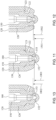
- the intermediate body 150 is linearly moveable relative to the outer valve body 120 between a first intermediate body position 1501 and a second intermediate body position 1502.
- first intermediate body position 1501 as shown in FIG. 11
- second intermediate body position 1502 as shown in FIG. 12
- the intermediate body 150 is spaced apart from the first valve seat 123, to form a communication between the first pressure chamber 126 and the first fuel nozzle 122.
- the needle valve 180 is linearly moveable relative to the intermediate body 150 between a first needle valve position 1801 and a second needle valve position 1802.
- first needle valve position 1801 as shown in FIG. 10
- the needle valve 180 abuts against and closely engages the second valve seat 153 to block a fluid communication between the second pressure chamber 156 and the second fuel nozzle 152.
- second needle valve position 1802 as shown in FIG. 12
- the needle valve 180 is spaced apart from the second valve seat 153 to form a communication between the second pressure chamber 156 with the second fuel nozzle 152.
- a first fuel such as liquid methanol
- a second fuel such as liquid diesel
- a second fuel is provided by a second fuel high-pressure pump or a second fuel storage vessel, to enter the second input channel 160, the first return channel 140, the second return channel 170, the first control chamber 129 , the second control chamber 159, the first control channel 127 , the second control channel 157 and the second pressure chamber 156 through the second fuel inlet 161.
- the first solenoid valve 191 is used to control the ejection and to block the ejection of the first fuel.
- the opening of the first solenoid valve 191 causes the second fuel in the first control chamber 129 to flow to the return outlet 176 through the first return channel 140 and the first solenoid valve 191, thereby causing the liquid pressure in the first control chamber 129 to be lower than the liquid pressure in the first pressure chamber 126, and at the same time, under the damping effect of the first control channel 127, a liquid pressure difference is formed between the first control chamber 129 and the first pressure chamber 126.
- the intermediate body 150 When the liquid pressure difference between the first control chamber 129 and the first pressure chamber 126 towards the direction away from the first fuel nozzle 122, exerts on the intermediate body 150 a thrusting force larger than the elastic force of the first elastic member 193, the intermediate body 150 is actuated by the first fuel in the first pressure chamber 126, to move linearly from a first intermediate body position 1501 ( FIG. 11 ) to a second intermediate body position 1502 ( FIG. 12 ).
- the intermediate body 150 at the second intermediate body position 1502 forms a communication between the first pressure chamber 126 and the first fuel nozzle 122, such that the first fuel can be ejected from the fuel injector 100 through the first fuel nozzle 122, to provide the first fuel to the engine of which the fuel injector 100 is installed on.
- the second fuel flows to the first control chamber 129 through the first control channel 127, such that the pressure in the first control chamber 129 increases.
- the intermediate body 150 returns to the first intermediate body position 1501 ( Fig. 11 ), closing the communication between the first pressure chamber 126 and the first fuel nozzle 122, thereby blocking the ejection of the first fuel from the first fuel nozzle 122.
- the second solenoid valve 192 is used to control the ejection or to block the ejection of the second fuel.
- the opening of the second solenoid valve 192 causes the second fuel in the second control chamber 159 to flow to the return outlet 176 through the second return channel 170 and the second solenoid valve 192.
- This causes a decrease in the liquid pressure of the second control chamber 159, and is lower than the liquid pressure in the second pressure chamber 156, and at the same time, under the damping effect of the second control channel 157, a liquid pressure difference is formed between the second control chamber 159 and the second pressure chamber 156.
- Needle valve 180 at second needle valve position 1802 forms a communication between the second pressure chamber 156 and the second fuel nozzle 152, such that a second fuel may be ejected from the fuel injector 100 through the second fuel nozzle 152, to provide the second fuel to the engine of which the fuel injector 100 is mounted to.
- the second solenoid valve 192 After the second solenoid valve 192 is closed, the second fuel flows to the second control chamber 159 through the second control channel 157, such that the pressure in the second control chamber 159 increases.
- the needle valve 180 resets to the first needle valve position 1801, closing the second pressure chamber 156 and the second fuel nozzle 152, thereby blocking the ejection of the second fuel from the second fuel nozzle 152.
- the injection of the first fuel and the second fuel can be controlled or blocked, thereby providing the engine with a first fuel and a second fuel.
Landscapes
- Engineering & Computer Science (AREA)
- Chemical & Material Sciences (AREA)
- Combustion & Propulsion (AREA)
- Mechanical Engineering (AREA)
- General Engineering & Computer Science (AREA)
- Physics & Mathematics (AREA)
- Fluid Mechanics (AREA)
- Electromagnetism (AREA)
- Oil, Petroleum & Natural Gas (AREA)
- Fuel-Injection Apparatus (AREA)
Applications Claiming Priority (2)
| Application Number | Priority Date | Filing Date | Title |
|---|---|---|---|
| CN202011565239.5A CN114687901B (zh) | 2020-12-25 | 2020-12-25 | 一种用于发动机的双燃料喷射器 |
| PCT/SG2021/050816 WO2022139684A1 (fr) | 2020-12-25 | 2021-12-22 | Injecteur de bicarburant pour un moteur |
Publications (2)
| Publication Number | Publication Date |
|---|---|
| EP4269780A1 true EP4269780A1 (fr) | 2023-11-01 |
| EP4269780A4 EP4269780A4 (fr) | 2024-12-18 |
Family
ID=82130913
Family Applications (1)
| Application Number | Title | Priority Date | Filing Date |
|---|---|---|---|
| EP21911686.0A Pending EP4269780A4 (fr) | 2020-12-25 | 2021-12-22 | Injecteur de bicarburant pour un moteur |
Country Status (3)
| Country | Link |
|---|---|
| EP (1) | EP4269780A4 (fr) |
| CN (1) | CN114687901B (fr) |
| WO (1) | WO2022139684A1 (fr) |
Family Cites Families (12)
| Publication number | Priority date | Publication date | Assignee | Title |
|---|---|---|---|---|
| DE849325C (de) * | 1940-09-19 | 1952-09-15 | Bosch Gmbh Robert | Einspritzventil fuer Brennkraftmaschinen |
| GB1435702A (en) * | 1972-06-12 | 1976-05-12 | Nat Res Dev | Injectors for the fuel injection systems of internal combustion engines |
| US4693227A (en) * | 1985-05-21 | 1987-09-15 | Toyota Jidosha Kabushiki Kaisha | Multi-fuel injection system for an internal combustion engine |
| JP4297181B2 (ja) * | 2007-07-17 | 2009-07-15 | 株式会社デンソー | インジェクタ |
| US9234452B2 (en) * | 2012-05-17 | 2016-01-12 | Caterpillar Inc. | Direct injection gas engine and method |
| JP5925104B2 (ja) * | 2012-10-19 | 2016-05-25 | 三菱重工業株式会社 | 燃料ガス噴射弁、デュアルフューエルガスエンジン及び燃料ガス噴射弁の噴射方法 |
| CN103244321B (zh) * | 2013-04-28 | 2015-03-11 | 哈尔滨工程大学 | 双燃料双压电控制式喷射器 |
| GB201309122D0 (en) * | 2013-05-21 | 2013-07-03 | Delphi Tech Holding Sarl | Fuel Injector |
| CN204900133U (zh) * | 2015-07-07 | 2015-12-23 | 中国人民解放军装甲兵工程学院 | 一种发动机双燃料同时喷射喷嘴 |
| CN208950750U (zh) * | 2018-09-21 | 2019-06-07 | 英嘉动力科技无锡有限公司 | 一种新型双燃料喷射器 |
| CN110594061B (zh) * | 2019-09-26 | 2021-02-26 | 重庆红江机械有限责任公司 | 一种电控共轨式重油喷油器 |
| CN215057845U (zh) * | 2020-12-25 | 2021-12-07 | Bmdi (新加坡)私人有限公司 | 一种用于发动机的双燃料喷射器 |
-
2020
- 2020-12-25 CN CN202011565239.5A patent/CN114687901B/zh active Active
-
2021
- 2021-12-22 EP EP21911686.0A patent/EP4269780A4/fr active Pending
- 2021-12-22 WO PCT/SG2021/050816 patent/WO2022139684A1/fr not_active Ceased
Also Published As
| Publication number | Publication date |
|---|---|
| WO2022139684A1 (fr) | 2022-06-30 |
| CN114687901B (zh) | 2026-04-24 |
| EP4269780A4 (fr) | 2024-12-18 |
| CN114687901A (zh) | 2022-07-01 |
Similar Documents
| Publication | Publication Date | Title |
|---|---|---|
| US8479711B2 (en) | Piezoelectric direct acting fuel injector with hydraulic link | |
| RU2426002C2 (ru) | Устройство впрыскивания топлива для двигателя внутреннего сгорания | |
| EP1059438B1 (fr) | Injecteur de carburant avec guide-aiguille tubulaire inférieur | |
| KR20160104059A (ko) | 이중 연료 인젝터 | |
| CN110017230A (zh) | 一种电液联控快速响应型高压共轨喷油器 | |
| KR101557521B1 (ko) | 대형 디젤엔진용 전기제어식 연료인젝터 | |
| EP4269780A1 (fr) | Injecteur de bicarburant pour un moteur | |
| CN111535958B (zh) | 一种双燃料喷射器及其喷射方法 | |
| US20190085807A1 (en) | High-pressure fuel pump | |
| CN215057845U (zh) | 一种用于发动机的双燃料喷射器 | |
| US20120286074A1 (en) | Valve assembly and injection valve | |
| US20160230728A1 (en) | Plunger And Fluid-Line System | |
| CN222910153U (zh) | 组合式双燃料喷射器 | |
| EP2034170B1 (fr) | Injecteur de carburant | |
| GB2364101A (en) | Pressure-controlled control part for common-rail fuel injectors | |
| JP3977620B2 (ja) | 燃料噴射弁 | |
| CN118728609A (zh) | 喷油器、发动机及动力车辆 | |
| US20060175436A1 (en) | Fuel injection device | |
| US20060219805A1 (en) | Fuel injection device | |
| CN121195110A (zh) | 双燃料喷射器 | |
| EP3594470A1 (fr) | Moteur à deux temps du type à balayage en équicourant | |
| CN211449693U (zh) | 一种流量平稳的燃油计量阀 | |
| KR900004901Y1 (ko) | 연료 분사노즐 | |
| EP1482170B1 (fr) | Buse d'injecteur avec injection améliorée et procédé de fabrication | |
| JP2019183718A (ja) | 燃料噴射弁 |
Legal Events
| Date | Code | Title | Description |
|---|---|---|---|
| STAA | Information on the status of an ep patent application or granted ep patent |
Free format text: STATUS: THE INTERNATIONAL PUBLICATION HAS BEEN MADE |
|
| PUAI | Public reference made under article 153(3) epc to a published international application that has entered the european phase |
Free format text: ORIGINAL CODE: 0009012 |
|
| STAA | Information on the status of an ep patent application or granted ep patent |
Free format text: STATUS: REQUEST FOR EXAMINATION WAS MADE |
|
| 17P | Request for examination filed |
Effective date: 20230720 |
|
| AK | Designated contracting states |
Kind code of ref document: A1 Designated state(s): AL AT BE BG CH CY CZ DE DK EE ES FI FR GB GR HR HU IE IS IT LI LT LU LV MC MK MT NL NO PL PT RO RS SE SI SK SM TR |
|
| DAV | Request for validation of the european patent (deleted) | ||
| DAX | Request for extension of the european patent (deleted) | ||
| A4 | Supplementary search report drawn up and despatched |
Effective date: 20241114 |
|
| RIC1 | Information provided on ipc code assigned before grant |
Ipc: F02D 19/06 20060101ALI20241108BHEP Ipc: F02M 61/18 20060101ALI20241108BHEP Ipc: F02M 61/10 20060101ALI20241108BHEP Ipc: F02M 47/02 20060101ALI20241108BHEP Ipc: F02M 51/06 20060101ALI20241108BHEP Ipc: F02M 43/04 20060101AFI20241108BHEP |