EP4269809A1 - Compresseur centrifuge et son procédé de fabrication - Google Patents
Compresseur centrifuge et son procédé de fabrication Download PDFInfo
- Publication number
- EP4269809A1 EP4269809A1 EP21908107.2A EP21908107A EP4269809A1 EP 4269809 A1 EP4269809 A1 EP 4269809A1 EP 21908107 A EP21908107 A EP 21908107A EP 4269809 A1 EP4269809 A1 EP 4269809A1
- Authority
- EP
- European Patent Office
- Prior art keywords
- vanes
- wall surface
- side wall
- return channel
- shroud
- Prior art date
- Legal status (The legal status is an assumption and is not a legal conclusion. Google has not performed a legal analysis and makes no representation as to the accuracy of the status listed.)
- Granted
Links
Images





Classifications
-
- F—MECHANICAL ENGINEERING; LIGHTING; HEATING; WEAPONS; BLASTING
- F04—POSITIVE - DISPLACEMENT MACHINES FOR LIQUIDS; PUMPS FOR LIQUIDS OR ELASTIC FLUIDS
- F04D—NON-POSITIVE-DISPLACEMENT PUMPS
- F04D17/00—Radial-flow pumps, e.g. centrifugal pumps; Helico-centrifugal pumps
- F04D17/08—Centrifugal pumps
- F04D17/10—Centrifugal pumps for compressing or evacuating
- F04D17/12—Multi-stage pumps
- F04D17/122—Multi-stage pumps the individual rotor discs being, one for each stage, on a common shaft and axially spaced, e.g. conventional centrifugal multi- stage compressors
-
- F—MECHANICAL ENGINEERING; LIGHTING; HEATING; WEAPONS; BLASTING
- F04—POSITIVE - DISPLACEMENT MACHINES FOR LIQUIDS; PUMPS FOR LIQUIDS OR ELASTIC FLUIDS
- F04D—NON-POSITIVE-DISPLACEMENT PUMPS
- F04D17/00—Radial-flow pumps, e.g. centrifugal pumps; Helico-centrifugal pumps
- F04D17/08—Centrifugal pumps
- F04D17/10—Centrifugal pumps for compressing or evacuating
- F04D17/12—Multi-stage pumps
-
- F—MECHANICAL ENGINEERING; LIGHTING; HEATING; WEAPONS; BLASTING
- F04—POSITIVE - DISPLACEMENT MACHINES FOR LIQUIDS; PUMPS FOR LIQUIDS OR ELASTIC FLUIDS
- F04D—NON-POSITIVE-DISPLACEMENT PUMPS
- F04D29/00—Details, component parts, or accessories
- F04D29/02—Selection of particular materials
- F04D29/023—Selection of particular materials especially adapted for elastic fluid pumps
-
- F—MECHANICAL ENGINEERING; LIGHTING; HEATING; WEAPONS; BLASTING
- F04—POSITIVE - DISPLACEMENT MACHINES FOR LIQUIDS; PUMPS FOR LIQUIDS OR ELASTIC FLUIDS
- F04D—NON-POSITIVE-DISPLACEMENT PUMPS
- F04D29/00—Details, component parts, or accessories
- F04D29/40—Casings; Connections of working fluid
- F04D29/42—Casings; Connections of working fluid for radial or helico-centrifugal pumps
- F04D29/44—Fluid-guiding means, e.g. diffusers
- F04D29/441—Fluid-guiding means, e.g. diffusers especially adapted for elastic fluid pumps
- F04D29/444—Bladed diffusers
-
- F—MECHANICAL ENGINEERING; LIGHTING; HEATING; WEAPONS; BLASTING
- F04—POSITIVE - DISPLACEMENT MACHINES FOR LIQUIDS; PUMPS FOR LIQUIDS OR ELASTIC FLUIDS
- F04D—NON-POSITIVE-DISPLACEMENT PUMPS
- F04D29/00—Details, component parts, or accessories
- F04D29/60—Mounting; Assembling; Disassembling
- F04D29/62—Mounting; Assembling; Disassembling of radial or helico-centrifugal pumps
- F04D29/624—Mounting; Assembling; Disassembling of radial or helico-centrifugal pumps especially adapted for elastic fluid pumps
-
- F—MECHANICAL ENGINEERING; LIGHTING; HEATING; WEAPONS; BLASTING
- F05—INDEXING SCHEMES RELATING TO ENGINES OR PUMPS IN VARIOUS SUBCLASSES OF CLASSES F01-F04
- F05D—INDEXING SCHEME FOR ASPECTS RELATING TO NON-POSITIVE-DISPLACEMENT MACHINES OR ENGINES, GAS-TURBINES OR JET-PROPULSION PLANTS
- F05D2230/00—Manufacture
- F05D2230/10—Manufacture by removing material
-
- F—MECHANICAL ENGINEERING; LIGHTING; HEATING; WEAPONS; BLASTING
- F05—INDEXING SCHEMES RELATING TO ENGINES OR PUMPS IN VARIOUS SUBCLASSES OF CLASSES F01-F04
- F05D—INDEXING SCHEME FOR ASPECTS RELATING TO NON-POSITIVE-DISPLACEMENT MACHINES OR ENGINES, GAS-TURBINES OR JET-PROPULSION PLANTS
- F05D2300/00—Materials; Properties thereof
- F05D2300/10—Metals, alloys or intermetallic compounds
Definitions
- the present invention relates to a centrifugal compressor and a method for manufacturing the centrifugal compressor.
- a centrifugal compressor includes: a centrifugal impeller rotated to give energy to fluid; a diffuser converting kinetic pressure of the fluid having increased pressure, into static pressure; a return channel provided with return vanes configured to remove tangential velocity components of the fluid; and the like.
- Patent Literature 1 As a return vane structure to efficiently redirect the flow and remove tangential velocity components of the fluid to straighten the flow, the structure of Patent Literature 1 is proposed.
- Patent Literature 1 discloses a tandem return vane structure that includes return vanes (hereinafter, referred to as front vanes) arranged on the upstream side and swirl removal members (rear vanes) arranged on the downstream side.
- front vanes return vanes
- swirl removal members rear vanes
- Paragraphs No. 0047 and No. 0053 disclose that the swirl removal members (rear vanes) are joined to a wall surface on the shroud side or a wall surface on the hub side.
- Patent Literature 1 JP2018-178769A
- the front vanes are directly joined to the hub- or shroud-side wall surface where the rear vanes are formed.
- the joining process requires a route for a welding rod or the like to be inserted from radially outside or inside the hub-side wall surface or shroud-side wall surface.
- the applicant had therefore previously designed the shape and layout of the front and rear vanes so as to avoid joining failure.
- the front and rear vanes designed as such had poor ability (hereinafter, also referred to as "a tangential velocity component removal ability") to remove tangential velocity components of fluid.
- the present invention was made in the light of the aforementioned circumstances, and an object thereof is to improve the tangential velocity component removal ability of the front and rear vanes provided in the return channel of a centrifugal compressor.
- the present invention provides a centrifugal compressor including a rotation shaft; plural centrifugal impellers, a diffuser, and a return channel.
- the plural centrifugal impellers are mounted on the rotation shaft.
- the diffuser causes fluid exiting one of the centrifugal impellers to flow in a centrifugal direction from the rotation shaft.
- the return channel is provided downstream of the diffuser and causes the fluid flowing from the diffuser to the centrifugal impeller of the subsequent stage to flow in a return direction toward the rotation shaft.
- the return channel is provided between a hub-side wall surface and a shroud-side wall surface.
- the return channel includes a front set of vanes arranged in a circular array on the upstream side and a rear set of vanes arranged in a circular array on the downstream side.
- the front set of vanes and the rear set of vanes are both formed on one of the hub-side wall surface or the shroud-side wall surface.
- One of the front set of vanes or the rear set of vanes is formed on an annular member that is formed separately from the other one of the front set of vanes or the rear set of vanes. The annular member is fitted to the return channel.
- a method for manufacturing a centrifugal compressor according to the present invention includes a formation step, a joining step, and a fitting step.
- the formation step one of a front set of vanes or a rear set of vanes is formed on an annular member formed separately from the other one of the front set of vanes or the rear set of vanes.
- the front set of vanes is arranged in a circular array on the upstream side in a return channel provided between a hub-side wall surface and a shroud-side wall surface.
- the rear set of vanes is arranged in a circular array on the downstream side.
- the other one of the front set of vanes or the rear set of vanes which is formed on one of the hub-side wall surface or the shroud-side wall surface, is joined to the other one of the hub-side wall surface or the shroud-side wall surface.
- the annular member is fitted to the return channel.
- FIG. 1 is an axial sectional view (a sectional view along a meridian plane) of a centrifugal compressor 100 according to a first embodiment of the present invention.
- the axial section (the section along a meridian plane) is a sectional plane of the centrifugal compressor 100 including a central axis of a rotation shaft 2, on which components are projected.
- FIG. 1 shows only the upper half of the centrifugal compressor 100.
- the centrifugal compressor 100 includes plural centrifugal impellers 1, the rotation shaft 2, diffusers 3, and a return channel 4.
- the centrifugal impellers 1 rotate to give energy to fluid.
- the centrifugal impellers 1 are mounted on the rotation shaft 2.
- FIG. 1 shows only two centrifugal impellers by way of example.
- the diffusers 3 are provided radially outside of the respective centrifugal impellers 1.
- the diffusers 3 cause fluid exiting the respective centrifugal impellers 1 to flow in the centrifugal direction from the rotation shaft 2.
- Each diffuser 3 converts kinetic pressure of the fluid exiting the centrifugal impeller 1 into static pressure.
- the return channel 4 is provided downstream of the corresponding diffuser 3 and guides the fluid to the centrifugal impeller 1 of the subsequent stage. Specifically, the return channel 4 causes the fluid flowing from the diffuser 3 to the centrifugal impeller 1 of the subsequent stage to flow in a return direction toward the rotation shaft 2.
- Each centrifugal impeller 1 includes plural blades 11, which are arranged at intervals in the circumferential direction.
- the blades 11 are typically positioned between a hub (a disk) 12, which is fastened to the rotation shaft 2, and a shroud (a side plate) 13, which is arranged facing the hub 12.
- Each centrifugal impeller 1 shown in the first embodiment is a closed centrifugal impeller example including the shroud 13.
- Each centrifugal impeller 1 may be an open centrifugal impeller not including the shroud 13.
- Each diffuser 3 is a vaneless diffuser not including a vane in the first embodiment.
- Each diffuser 3 may be a vaned diffuser including plural vanes arranged at a substantially equal pitch in the circumferential direction.
- the return channel 4 has a role in removing tangential velocity components of fluid flowing through the return channel 4 to straighten the flow while causing the fluid to flow to the centrifugal impeller 1 of the next stage.
- the return channel 4 includes plural return vanes 6.
- the return vanes 6 are arranged at a substantially equal pitch in the circumferential direction around the central axis of the rotation shaft 2. The detail thereof is described later.
- the centrifugal impellers 1, rotation shaft 2, diffusers 3, and return channel 4 are accommodated in a casing 5.
- the casing 5 is supported by flanges 51 and 52.
- a suction channel 53 is provided on the fluid suction side of the casing 5.
- a discharge channel 54 is provided on the fluid discharge side of the casing 5.
- the centrifugal compressor 100 includes radial bearings 55 and 56 on respective ends of the rotation shaft 2.
- the radial bearings 55 and 56 rotationally support the rotation shaft 2.
- fluid suctioned through the suction channel 53 increases in pressure each time the fluid passes through the centrifugal impeller 1, diffuser 3, and return channel 4 of each stage and finally reaches a predetermined pressure to be discharged from the discharge channel 54.
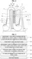
- FIG. 2 is an enlarged sectional view of Area A of FIG. 1 .
- the return channel 4 includes a return bend portion 41 and a return vane portion 42.
- the return bend portion 41 includes a first redirection portion 411 and a second redirection portion 412.
- the first redirection portion 411 the fluid having flowed through the diffuser 3 is then redirected from the radially outward direction to the axial direction.
- the second redirection portion 412 the fluid having flowed through the first redirection portion 411 is further redirected from the axial direction to the radially inward direction.
- the return vane portion 42 is a channel provided with the return vanes 6.
- the return channel 4 is provided between a hub-side wall surface 80 and a shroud-side wall surface 90.
- the shroud-side wall surface 90 is a wall surface within the return channel 4 on the side where fluid having passed on the shroud 13 side of the centrifugal impeller 1 mainly flows.
- the shroud-side wall surface 90 includes a portion of wall surface on the right side in FIG. 2 in the return vane portion 42, corresponding to the surface of an external structure 9, which is fixed to the casing 5.
- the hub-side wall surface 80 is a wall surface within the return channel 4 on the side where fluid having passed on the hub 12 side of the centrifugal impeller 1 mainly flows.
- the hub-side wall surface 80 includes a portion of wall surface on the left side in FIG. 2 in the return vane portion 42, corresponding to the surface of an internal structure 8, which is fixed to the external structure 9 through the return vanes 6.
- the return vanes 6 include front vanes 61 and rear vanes 62.
- the return vanes 6 are tandem return vanes.
- the rear vanes 62 are provided downstream of the front vanes 61.
- the front vanes 61 are arranged in a circular array on the upstream side while the rear vanes 62 are arranged in a circular array on the downstream side (see FIG. 5 ).
- the front vanes 61 and the rear vanes 62 have a relationship of: innermost diameter D1 of the front vanes 61 > outermost diameter D2 of the rear vanes 62.
- the gap provided between the front vanes 61 and the rear vanes 62 in the radial direction is designed to be small in order to improve the tangential velocity component removal ability.
- FIG. 3 is a flowchart showing a method for manufacturing the return vane structure of the first embodiment.
- annular member 92 on which the front vanes 61 (see FIG. 5 ) are not yet formed (before formation of front vanes), and a shroud-side structure 91, on which the rear vanes 62 (see FIG. 5 ) are not yet formed (before formation of rear vanes), are temporarily joined (S11).
- FIG. 4 is a perspective view of the annular member 92 before formation of front vanes and the shroud-side structure 91 before formation of rear vanes that are temporarily joined.
- the annular member 92 before formation of front vanes and the shroud-side structure 91 before formation of rear vanes are each composed of an annular metallic material.
- a small-diameter portion 93 (also see FIG. 6 ) is provided in the return channel 4 side of the shroud-side structure 91.
- the small-diameter portion 93 has an outer diameter smaller than part of the shroud-side structure 91 on the side opposite to the return channel 4.
- the annular member 92 before formation of front vanes and the shroud-side structure 91 before formation of rear vanes are positioned concentrically and are temporarily joined.
- the annular member 92 is located radially outside of the small-diameter portion 93 of the shroud-side structure 91.
- the positioning and temporary joining processes are performed using a fastening member (not shown), such as a bolt or a dowel pin for general use, that extends radially from the outside toward the inside and can be subsequently unfastened.
- the fastening member is positioned so as not to interfere with a tool at forming the front and rear vanes 61 and 62 in a subsequent process.
- the relative positions of the annular member 92 before formation of front vanes to the shroud-side structure 91 before formation of rear vanes is thus prevented from moving.
- the annular member 92 before formation of front vanes and the shroud-side structure 91 before formation of rear vanes each have a half-split structure.
- the annular member 92 before formation of front vanes and the shroud-side structure 91 before formation of rear vanes are fixed to each other with a jig or the like so as to maintain the state shown in FIG. 4 .
- FIG. 5 is a perspective view of an annular member 92a and a shroud-side structure 91a with the front vanes 61 and the rear vanes 62 respectively formed thereon.
- the front vanes 61 and the rear vanes 62 are formed in the structure shown in FIG. 4 .
- the formation process herein is machining, such as cutting, for example. This ensures the relative position of the front vanes 61 to the rear vanes 62 with a processing accuracy of a typical processing machine.
- annular member 92a after formation of front vanes and the shroud-side structure 91a after formation of rear vanes are disassembled from each other(S13).
- FIG. 6 is a perspective view of the shroud-side structure 91a with the rear vanes 62 formed thereon.
- FIG. 7 is a perspective view of the annular member 92a with the front vanes 61 formed thereon.
- the disassembling process is performed by unfastening the fastening member (not shown), such as a bolt or a dowel pin.
- FIG. 8 is a perspective view of a structure obtained by joining the rear vanes 62 formed on the shroud-side structure 91a to the internal structure 8.
- the rear vanes 62 of the structure shown in FIG. 6 and the internal structure 8 are joined by a joining process, such as welding.
- the return vanes 6 as the tandem return vanes can be joined to the internal structure 8 equally to joining of single-array return vanes to the internal structure 8. It is therefore possible to ease the limiting condition for the gap between the front vanes 61 and the rear vanes 62 concerning the manufacturability of the tandem return vanes.
- FIG. 9 is a perspective view of a structure obtained by splitting the structure shown in FIG. 7 into halves and fitting the halves to the structure shown in FIG. 8 from radially outside.
- FIG. 10 is an enlarged sectional view of the return bane structure of the first embodiment.
- FIG. 10 is an axial sectional view (a sectional view along a meridian plane) of the structure shown in FIG. 9 .
- FIG. 10 shows only the upper half (Area A in FIG. 1 ).
- the fitting process is performed using a fastening member (not shown), such as a bolt or a dowel pin.
- the annular member 92a and the shroud-side structure 91a constitute the external structure 9.
- the internal structure 8 is fixed to the external structure 9 through the rear vanes 62 and is not joined to the front vanes 61.
- the return vane structure including the front vanes 61, rear vanes 62, internal structure 8, and external structure 9 is formed as shown in FIG. 2 .
- the front vanes 61 are formed on the annular member 92a, which is formed separately from the rear vanes 62, in the formation step (S12).
- the joining step (S14) the rear vanes 62 formed on the shroud-side wall surface 90 are joined to the hub-side wall surface 80.
- the annular member 92a is fitted to the return channel 4 in the fitting step (S15).
- the split halves of the return vane structure are built in and fixed to respective split halves of the casing 5.
- the split halves of the casing 5 with the split halves of the return vane structure built therein are then integrated by being joined to each other.
- the return channel 4 is provided between the hub-side wall surface 80 and the shroud-side wall surface 90.
- the return channel 4 includes the front vanes 61, which are arranged in a circular array on the upstream side, and the rear vanes 62, which are arranged in a circular array on the downstream side.
- the array of front vanes 61 and the array of rear vanes 62 are both formed on the shroud-side wall surface 90.
- the front vanes 61 are formed on the annular member 92a, which is formed separately from the rear vanes 62.
- the annular member 92a is fitted to the return channel 4.
- the front vanes 61 are formed on the annular member 92a, which is formed separately from the rear vanes 62, and the annular member 92a is fitted to the return channel 4.
- the joining process for the tandem return vanes for example, which include the front vanes 61 and rear vanes 62, can be performed equally to joining of the single-array return vanes. That is, any situation does not occur in which the joining operation is complicated because the welding rod cannot easily reach between the front vanes 61 and rear vanes 62 through gaps in the outer or inner circumference when the hub-side wall surface 80 and the shroud-side wall surface 90 face each other with the front and rear vanes 61 and 62 interposed therebetween.
- the gap between the front vanes 61 and the rear vanes 62 therefore can be configured to be small in order to improve the tangential velocity component removal ability.
- tandem return vanes that facilitates joining the vanes without limiting the shape of the front and rear vanes 61 and 62 in particular. Improved interaction between the front and rear vanes 61 and 62, which is important to the tandem return vanes, for example, enhances the ability to remove tangential velocity components of the fluid.
- the vanes not formed on the annular member 92a are formed by direct processing for the wall surface of the return channel 4.
- the return vane structure including the front and rear vanes 61 and 62 can be easily formed by fitting the annular member 92a, as a different body, with the vanes formed thereon to the return channel 4.
- the front vanes 61 are formed on the annular member 92a, and the rear vanes 62 are formed by direct processing for the wall surface of the return channel 4.
- the annular member 92a with the front banes 61 formed thereon can be easily fitted to the return channel 4 from radially outside.
- the innermost diameter D1 of the front vanes 61 is greater than the outermost diameter D2 of the rear vanes 62.
- the inner surface of the annular member 92a is configured to be a cylindrical surface. The annular member 92a therefore has a simple structure and can be easily fitted to the return channel 4.
- FIGS. 11 and 12 a second embodiment of the present invention will be described, focusing on different points from the aforementioned first embodiment. The description of the same points is omitted properly.
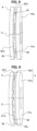
- FIG. 11 is an enlarged sectional view of a return vane structure of the second embodiment.
- FIG. 11 shows only the upper half (Area A in FIG. 1 ).
- the second embodiment is different from the first embodiment in that the array of front vanes 61 and the array of rear vanes 62 are both formed on the hub-side wall surface 80.
- the front vanes 61 are formed on an annular member 82a, which is formed separately from the rear vanes 62.
- the annular member 82a is fitted to the return channel 4.
- the annular member 82a is arranged and fitted radially outside of a small-diameter portion 83, which is provided in the return channel 4 side of a hub-side structure 81a.
- FIG. 12 is a flowchart showing a method for manufacturing the return vane structure of the second embodiment.
- the method for manufacturing the return vane structure will be described in the order shown in the flowchart of FIG. 12 .
- annular member (not shown) on which the front vanes 61 are not yet formed (before formation of front vanes) and a hub-side structure on which the rear vanes 62 are not yet formed. (before formation of rear vanes) are temporarily joined (S21).
- a formation step of forming the front vanes 61 and the rear vanes 62 is performed (S22).
- the front vanes 61 are formed on the annular member 82a, which is formed separately from the rear vanes 62.
- annular member 82a after formation of front vanes and the hub-side structure 81a after formation of rear vanes are disassembled from each other (S23).
- a joining step of joining the rear vanes 62 formed on the hub-side structure 81a to the external structure 9 is performed (S24) .
- the joining step (S24) the rear vanes 62 formed on the hub-side wall surface 80 are joined to the shroud-side wall surface 90.
- a fitting step of fitting the annular member 82a after formation of front vanes is performed (S25). Specifically, after the joining step (S24), the annular member 82a is fitted to the return channel 4 in the fitting step (S25).
- the annular member 82a and the hub-side structure 81a constitute the internal structure 8.
- the return vane structure including the front vanes 61, rear vanes 62, internal structure 8, and external structure 9 is formed as shown in FIG. 2 .
- the second embodiment similarly to the first embodiment, it is possible to improve the tangential velocity component removal ability of the front and rear vanes 61 and 62, which are provided for the return channel 4 of the centrifugal compressor 100.
- the present invention is described based on the embodiments.
- the present invention is not limited to the aforementioned embodiments and include various modifications.
- the aforementioned embodiments are described in detail for easy understanding of the present invention and are not always limited to ones including all the configurations described above.
- Part of the configuration of any one of the embodiments can be substituted with the corresponding configuration of the other embodiment, and the configuration of any one of the embodiments can be added with the configuration of the other embodiment.
- Part of the configuration of each embodiment can be added or substituted with another configuration or can be deleted.
- the front vanes 61 are formed on the annular member 92a or 82a, and the rear vanes 62 are formed by direct processing for the wall surface of the return channel 4.
- the present invention is not limited thereto.
- the rear vanes 62 may be formed on the annular member (not shown) while the front vanes 61 are formed by direct processing for the wall surface of the return channel 4.
- the return vanes 6, which are provided for the return channel 4 are tandem return vanes including the front and rear vanes 61 and 62.
- the present invention is not limited thereto.
- the return channel 4 may be provided with three circular arrays of vanes arranged from upstream to downstream. In this case, two of the three arrays of vanes that are radially adjacent to each other correspond to the front and rear vanes of the present invention.
Landscapes
- Engineering & Computer Science (AREA)
- Mechanical Engineering (AREA)
- General Engineering & Computer Science (AREA)
- Structures Of Non-Positive Displacement Pumps (AREA)
Applications Claiming Priority (2)
| Application Number | Priority Date | Filing Date | Title |
|---|---|---|---|
| JP2020212725A JP7576455B2 (ja) | 2020-12-22 | 2020-12-22 | 遠心圧縮機およびその製造方法 |
| PCT/JP2021/039638 WO2022137794A1 (fr) | 2020-12-22 | 2021-10-27 | Compresseur centrifuge et son procédé de fabrication |
Publications (3)
| Publication Number | Publication Date |
|---|---|
| EP4269809A1 true EP4269809A1 (fr) | 2023-11-01 |
| EP4269809A4 EP4269809A4 (fr) | 2024-11-20 |
| EP4269809B1 EP4269809B1 (fr) | 2025-12-24 |
Family
ID=82159026
Family Applications (1)
| Application Number | Title | Priority Date | Filing Date |
|---|---|---|---|
| EP21908107.2A Active EP4269809B1 (fr) | 2020-12-22 | 2021-10-27 | Compresseur centrifuge et son procédé de fabrication |
Country Status (4)
| Country | Link |
|---|---|
| US (1) | US20230417255A1 (fr) |
| EP (1) | EP4269809B1 (fr) |
| JP (1) | JP7576455B2 (fr) |
| WO (1) | WO2022137794A1 (fr) |
Family Cites Families (10)
| Publication number | Priority date | Publication date | Assignee | Title |
|---|---|---|---|---|
| US3044684A (en) * | 1961-02-24 | 1962-07-17 | Cooper Bessemer Corp | Centrifugal compressor construction |
| US4344737A (en) * | 1978-01-30 | 1982-08-17 | The Garrett Corporation | Crossover duct |
| US4251183A (en) * | 1978-01-30 | 1981-02-17 | The Garrett Corp. | Crossover duct assembly |
| JPH01149597U (fr) * | 1988-04-05 | 1989-10-17 | ||
| JP3299638B2 (ja) * | 1994-09-20 | 2002-07-08 | 株式会社日立製作所 | ターボ流体機械 |
| JP2004150404A (ja) | 2002-11-01 | 2004-05-27 | Mitsubishi Heavy Ind Ltd | ベーンドディフューザ及び該ディフューザを備えた輻流ターボ機械 |
| DE102016203305A1 (de) | 2016-03-01 | 2017-09-07 | Siemens Aktiengesellschaft | Rückführstufe, Radialturbofluidenergiemaschine |
| JP6730955B2 (ja) | 2017-03-31 | 2020-07-29 | 新日本造機株式会社 | 多段遠心ポンプおよび該多段遠心ポンプの製造方法 |
| JP6854687B2 (ja) | 2017-04-05 | 2021-04-07 | 株式会社日立インダストリアルプロダクツ | 多段流体機械 |
| JP7019446B2 (ja) * | 2018-02-20 | 2022-02-15 | 三菱重工サーマルシステムズ株式会社 | 遠心圧縮機 |
-
2020
- 2020-12-22 JP JP2020212725A patent/JP7576455B2/ja active Active
-
2021
- 2021-10-27 WO PCT/JP2021/039638 patent/WO2022137794A1/fr not_active Ceased
- 2021-10-27 US US18/036,851 patent/US20230417255A1/en not_active Abandoned
- 2021-10-27 EP EP21908107.2A patent/EP4269809B1/fr active Active
Also Published As
| Publication number | Publication date |
|---|---|
| EP4269809A4 (fr) | 2024-11-20 |
| WO2022137794A1 (fr) | 2022-06-30 |
| US20230417255A1 (en) | 2023-12-28 |
| EP4269809B1 (fr) | 2025-12-24 |
| JP2022099003A (ja) | 2022-07-04 |
| JP7576455B2 (ja) | 2024-10-31 |
Similar Documents
| Publication | Publication Date | Title |
|---|---|---|
| JP4047330B2 (ja) | 独立通路ディフューザ | |
| US6279322B1 (en) | Deswirler system for centrifugal compressor | |
| US8100643B2 (en) | Centrifugal compressor vane diffuser wall contouring | |
| US11859543B2 (en) | Diffuser pipe with exit flare | |
| JP2008025575A (ja) | ターボ機械用のディフューザ/ガイドベーンアセンブリ | |
| WO2008124656A1 (fr) | Ventilateur annulaire et système de guidage d'air à capot | |
| CN107076159A (zh) | 具有粗糙的壁表面的多级的涡轮压缩机的或涡轮膨胀机的返回级 | |
| CN102414452A (zh) | 离心式压缩机 | |
| US10422345B2 (en) | Centrifugal compressor curved diffusing passage portion | |
| CN110130999B (zh) | 用于轴流式涡轮发动机的结构壳体 | |
| US20190285085A1 (en) | Refrigeration system mixed-flow compressor | |
| JP2010156329A (ja) | 蒸気タービン排気ディフューザに関する方法、システム及び/又は装置 | |
| RU2011108828A (ru) | Уменьшенный моноблочный многоступенчатый барабан осевого компрессора | |
| CN110418896B (zh) | 回引级和径流式涡轮流体能量机械 | |
| CN112449670B (zh) | 用于压缩机的无导叶超音速扩散器 | |
| US3905721A (en) | Centrifugal compressor diffuser | |
| CN112334665A (zh) | 用于制冷系统的混流式压缩机构造 | |
| JP2016031064A (ja) | 多段ポンプ | |
| JP7272815B2 (ja) | 多段遠心流体機械 | |
| US20160195110A1 (en) | Rotor for a thermal turbomachine | |
| US10823195B2 (en) | Diffuser pipe with non-axisymmetric end wall | |
| EP4269809B1 (fr) | Compresseur centrifuge et son procédé de fabrication | |
| CN105408585B (zh) | 用于热力涡轮机的转子 | |
| US20120183395A1 (en) | Radial compressor diffuser | |
| JP2010265784A (ja) | 遠心圧縮機 |
Legal Events
| Date | Code | Title | Description |
|---|---|---|---|
| STAA | Information on the status of an ep patent application or granted ep patent |
Free format text: STATUS: UNKNOWN |
|
| STAA | Information on the status of an ep patent application or granted ep patent |
Free format text: STATUS: THE INTERNATIONAL PUBLICATION HAS BEEN MADE |
|
| PUAI | Public reference made under article 153(3) epc to a published international application that has entered the european phase |
Free format text: ORIGINAL CODE: 0009012 |
|
| STAA | Information on the status of an ep patent application or granted ep patent |
Free format text: STATUS: REQUEST FOR EXAMINATION WAS MADE |
|
| 17P | Request for examination filed |
Effective date: 20230724 |
|
| AK | Designated contracting states |
Kind code of ref document: A1 Designated state(s): AL AT BE BG CH CY CZ DE DK EE ES FI FR GB GR HR HU IE IS IT LI LT LU LV MC MK MT NL NO PL PT RO RS SE SI SK SM TR |
|
| DAV | Request for validation of the european patent (deleted) | ||
| DAX | Request for extension of the european patent (deleted) | ||
| A4 | Supplementary search report drawn up and despatched |
Effective date: 20241017 |
|
| RIC1 | Information provided on ipc code assigned before grant |
Ipc: F04D 29/02 20060101ALI20241011BHEP Ipc: F04D 29/62 20060101ALI20241011BHEP Ipc: F04D 17/12 20060101ALI20241011BHEP Ipc: F04D 29/44 20060101AFI20241011BHEP |
|
| GRAP | Despatch of communication of intention to grant a patent |
Free format text: ORIGINAL CODE: EPIDOSNIGR1 |
|
| STAA | Information on the status of an ep patent application or granted ep patent |
Free format text: STATUS: GRANT OF PATENT IS INTENDED |
|
| INTG | Intention to grant announced |
Effective date: 20250729 |
|
| GRAS | Grant fee paid |
Free format text: ORIGINAL CODE: EPIDOSNIGR3 |
|
| GRAA | (expected) grant |
Free format text: ORIGINAL CODE: 0009210 |
|
| STAA | Information on the status of an ep patent application or granted ep patent |
Free format text: STATUS: THE PATENT HAS BEEN GRANTED |
|
| AK | Designated contracting states |
Kind code of ref document: B1 Designated state(s): AL AT BE BG CH CY CZ DE DK EE ES FI FR GB GR HR HU IE IS IT LI LT LU LV MC MK MT NL NO PL PT RO RS SE SI SK SM TR |
|
| REG | Reference to a national code |
Ref country code: CH Ref legal event code: F10 Free format text: ST27 STATUS EVENT CODE: U-0-0-F10-F00 (AS PROVIDED BY THE NATIONAL OFFICE) Effective date: 20251224 Ref country code: GB Ref legal event code: FG4D |
|
| REG | Reference to a national code |
Ref country code: DE Ref legal event code: R096 Ref document number: 602021045231 Country of ref document: DE |
|
| REG | Reference to a national code |
Ref country code: LT Ref legal event code: MG9D |
|
| PG25 | Lapsed in a contracting state [announced via postgrant information from national office to epo] |
Ref country code: NO Free format text: LAPSE BECAUSE OF FAILURE TO SUBMIT A TRANSLATION OF THE DESCRIPTION OR TO PAY THE FEE WITHIN THE PRESCRIBED TIME-LIMIT Effective date: 20260324 |
|
| PG25 | Lapsed in a contracting state [announced via postgrant information from national office to epo] |
Ref country code: HR Free format text: LAPSE BECAUSE OF FAILURE TO SUBMIT A TRANSLATION OF THE DESCRIPTION OR TO PAY THE FEE WITHIN THE PRESCRIBED TIME-LIMIT Effective date: 20251224 Ref country code: FI Free format text: LAPSE BECAUSE OF FAILURE TO SUBMIT A TRANSLATION OF THE DESCRIPTION OR TO PAY THE FEE WITHIN THE PRESCRIBED TIME-LIMIT Effective date: 20251224 |
|
| PG25 | Lapsed in a contracting state [announced via postgrant information from national office to epo] |
Ref country code: RS Free format text: LAPSE BECAUSE OF FAILURE TO SUBMIT A TRANSLATION OF THE DESCRIPTION OR TO PAY THE FEE WITHIN THE PRESCRIBED TIME-LIMIT Effective date: 20260324 |
|
| PG25 | Lapsed in a contracting state [announced via postgrant information from national office to epo] |
Ref country code: LV Free format text: LAPSE BECAUSE OF FAILURE TO SUBMIT A TRANSLATION OF THE DESCRIPTION OR TO PAY THE FEE WITHIN THE PRESCRIBED TIME-LIMIT Effective date: 20251224 |