EP4269821A1 - Système de fixation permettant de fixer un élément encastrable à une structure de plancher dans un véhicule - Google Patents
Système de fixation permettant de fixer un élément encastrable à une structure de plancher dans un véhicule Download PDFInfo
- Publication number
- EP4269821A1 EP4269821A1 EP22171054.4A EP22171054A EP4269821A1 EP 4269821 A1 EP4269821 A1 EP 4269821A1 EP 22171054 A EP22171054 A EP 22171054A EP 4269821 A1 EP4269821 A1 EP 4269821A1
- Authority
- EP
- European Patent Office
- Prior art keywords
- receiving
- fastening
- segments
- fastening system
- fastening element
- Prior art date
- Legal status (The legal status is an assumption and is not a legal conclusion. Google has not performed a legal analysis and makes no representation as to the accuracy of the status listed.)
- Pending
Links
Images


Classifications
-
- B—PERFORMING OPERATIONS; TRANSPORTING
- B64—AIRCRAFT; AVIATION; COSMONAUTICS
- B64D—EQUIPMENT FOR FITTING IN OR TO AIRCRAFT; FLIGHT SUITS; PARACHUTES; ARRANGEMENT OR MOUNTING OF POWER PLANTS OR PROPULSION TRANSMISSIONS IN AIRCRAFT
- B64D11/00—Passenger or crew accommodation; Flight-deck installations not otherwise provided for
- B64D11/06—Arrangements of seats, or adaptations or details specially adapted for aircraft seats
- B64D11/0696—Means for fastening seats to floors, e.g. to floor rails
-
- F—MECHANICAL ENGINEERING; LIGHTING; HEATING; WEAPONS; BLASTING
- F16—ENGINEERING ELEMENTS AND UNITS; GENERAL MEASURES FOR PRODUCING AND MAINTAINING EFFECTIVE FUNCTIONING OF MACHINES OR INSTALLATIONS; THERMAL INSULATION IN GENERAL
- F16B—DEVICES FOR FASTENING OR SECURING CONSTRUCTIONAL ELEMENTS OR MACHINE PARTS TOGETHER, e.g. NAILS, BOLTS, CIRCLIPS, CLAMPS, CLIPS OR WEDGES; JOINTS OR JOINTING
- F16B19/00—Bolts without screw-thread; Pins, including deformable elements; Rivets
- F16B19/02—Bolts or sleeves for positioning of machine parts, e.g. notched taper pins, fitting pins, sleeves, eccentric positioning rings
-
- F—MECHANICAL ENGINEERING; LIGHTING; HEATING; WEAPONS; BLASTING
- F16—ENGINEERING ELEMENTS AND UNITS; GENERAL MEASURES FOR PRODUCING AND MAINTAINING EFFECTIVE FUNCTIONING OF MACHINES OR INSTALLATIONS; THERMAL INSULATION IN GENERAL
- F16B—DEVICES FOR FASTENING OR SECURING CONSTRUCTIONAL ELEMENTS OR MACHINE PARTS TOGETHER, e.g. NAILS, BOLTS, CIRCLIPS, CLAMPS, CLIPS OR WEDGES; JOINTS OR JOINTING
- F16B37/00—Nuts or like thread-engaging members
- F16B37/08—Quickly-detachable or mountable nuts, e.g. consisting of two or more parts; Nuts movable along the bolt after tilting the nut
- F16B37/0807—Nuts engaged from the end of the bolt, e.g. axially slidable nuts
- F16B37/085—Nuts engaged from the end of the bolt, e.g. axially slidable nuts with at least one unthreaded portion in both the nut and the bolt
-
- F—MECHANICAL ENGINEERING; LIGHTING; HEATING; WEAPONS; BLASTING
- F16—ENGINEERING ELEMENTS AND UNITS; GENERAL MEASURES FOR PRODUCING AND MAINTAINING EFFECTIVE FUNCTIONING OF MACHINES OR INSTALLATIONS; THERMAL INSULATION IN GENERAL
- F16B—DEVICES FOR FASTENING OR SECURING CONSTRUCTIONAL ELEMENTS OR MACHINE PARTS TOGETHER, e.g. NAILS, BOLTS, CIRCLIPS, CLAMPS, CLIPS OR WEDGES; JOINTS OR JOINTING
- F16B5/00—Joining sheets or plates, e.g. panels, to one another or to strips or bars parallel to them
- F16B5/02—Joining sheets or plates, e.g. panels, to one another or to strips or bars parallel to them by means of fastening members using screw-thread
-
- F—MECHANICAL ENGINEERING; LIGHTING; HEATING; WEAPONS; BLASTING
- F16—ENGINEERING ELEMENTS AND UNITS; GENERAL MEASURES FOR PRODUCING AND MAINTAINING EFFECTIVE FUNCTIONING OF MACHINES OR INSTALLATIONS; THERMAL INSULATION IN GENERAL
- F16B—DEVICES FOR FASTENING OR SECURING CONSTRUCTIONAL ELEMENTS OR MACHINE PARTS TOGETHER, e.g. NAILS, BOLTS, CIRCLIPS, CLAMPS, CLIPS OR WEDGES; JOINTS OR JOINTING
- F16B5/00—Joining sheets or plates, e.g. panels, to one another or to strips or bars parallel to them
- F16B5/06—Joining sheets or plates, e.g. panels, to one another or to strips or bars parallel to them by means of clamps or clips
- F16B5/0607—Joining sheets or plates, e.g. panels, to one another or to strips or bars parallel to them by means of clamps or clips joining sheets or plates to each other
- F16B5/0621—Joining sheets or plates, e.g. panels, to one another or to strips or bars parallel to them by means of clamps or clips joining sheets or plates to each other in parallel relationship
- F16B5/065—Joining sheets or plates, e.g. panels, to one another or to strips or bars parallel to them by means of clamps or clips joining sheets or plates to each other in parallel relationship the plates being one on top of the other and distanced from each other, e.g. by using protrusions to keep contact and distance
Definitions
- the invention relates to a fastening system for fastening an installation element to a floor structure in a vehicle, as well as a vehicle with a floor structure and at least one installation element fastened by means of the fastening system.
- elongated rails comprising a cavity are usually used, which have a slot through which several openings are present.
- Suitable fastening elements are introduced into the cavity through the openings, moved along the slot into a section located between two successive openings and clamped there to the rail.
- a rail and conventional fastening elements are not optimal for a quicker configuration of a vehicle cabin.
- Floor rails made of a fiber-reinforced plastic with an omega-shaped cross section have advantages in terms of weight and are also convenient for variable attachment of fasteners.
- a fastening system for fastening an installation element to a floor structure in a vehicle comprising an elongated floor rail, at least one receiving socket, at least one fastening element with an insertion section, and a support section arranged on the installation element or which can be coupled thereto, the floor rail having a plurality of receiving openings for the Has receiving bushings, wherein the support section has at least one through hole, the receiving bushings each having a first positive locking means, the at least one fastening element having a second positive locking means complementary to the first positive locking means, the receiving bushings being connectable to the floor rail in the receiving openings, and wherein the at least one fastening element is designed to produce a positive connection between the first and the second positive locking means with the insertion section protruding through the through hole with one of the receiving sockets by inserting and / or rotating the insertion section in the relevant receiving socket, so that the support section is connected to the floor rail .
- the elongated floor rail can be made of a fiber-reinforced plastic. It could include an omega-shaped cross section. An upper boundary of the floor rail borders laterally on a floor formed in the cabin or is integrated therein. The upper limit can be designed as a largely flat surface in which the receiving openings are located condition.
- Two separate stiffening profiles could be arranged on the underside of the surface and also run along the longitudinal extent of the rail.
- the stiffening profiles could, for example, each comprise an L-shaped cross section with two legs that are exemplarily perpendicular to one another, with a lower leg running at a distance from and parallel to the surface of the upper boundary and can be directed laterally outwards. The other leg preferably runs perpendicular to the lower leg and the surface of the upper boundary.
- Both stiffening profiles can be spaced apart and mirror-inverted to one another, so that a space is formed between the two vertical legs of the two stiffening profiles. This space could be intended to be attached to a floor support that is connected to a hull structure of the vehicle.
- the bottom rail has a plurality of receiving openings, which are preferably accessible from an upper side of the bottom rail.
- the receiving openings can be distributed equidistantly along the longitudinal extent of the bottom rail.
- the receiving openings are intended to accommodate receiving sockets. These can be connected to the receiving openings or other profile sections of the floor rail.
- the receiving sockets are each designed to complement the at least one fastening element.
- the fastening element is intended to selectively form a positive connection with a receiving socket.
- the fastening element has the insertion section and, if necessary, a shaft section adjacent thereto.
- the fastening element can be inserted through a corresponding through hole in a support section, so that the fastening element then protrudes through. This achieves a fixation of the support section on the fastening element.
- the fastening element can form a preferably positive connection with one of the receiving sockets, so that The support section is fastened to the floor rail through a connection between the receiving socket and the floor rail and the fastening element and the receiving socket.
- the two form-fitting means are provided to achieve a connection between the fastening element and the receiving socket.
- the fastening element therefore allows an installation element to be inserted and fastened from a point above the floor rail by simply inserting and/or rotating.
- the fasteners can also be reopened, relocated, and reattached. Moving the support section on the floor rail, which preferably has a flat surface, is particularly easy. Through a simple attachment using the at least one fastening element and the receiving socket, a quick and simple reconfiguration can be achieved overall.
- the receiving bushings are designed to be positively and/or non-positively connected to the receiving openings.
- the receiving sockets could be arranged in the receiving openings and fastened there during the production of the floor rail. However, it is also conceivable that the receiving sockets are only brought into a corresponding receiving opening and fastened there when necessary. Fastening could be done by screwing, bracing, snapping or similar processes. If the receiving bushings are already inserted during the production of the floor rail, it could also be advisable to connect them to the floor rail in a materially bonded manner.
- the receiving bushings have a fastening opening in which the first positive locking means is arranged in the form of first circumferential grooves, which are divided in the circumferential direction into a plurality of first segments, with free first spaces between the first segments are provided without first circumferential grooves, wherein the insertion section has second circumferential grooves on a radially outer surface, which are divided into a plurality of second segments, free second spaces without second circumferential grooves being provided between the second segments, and wherein the second segments are dimensioned to be axial to be inserted into the first gaps in order to form a positive connection with the first segments after subsequent rotation of the fastening element.
- the insertion section can therefore be placed in a first rotational position relative to the receiving socket and inserted axially directly into the receiving socket.
- the first circumferential grooves mesh with the second circumferential grooves and consequently form a positive connection.
- the first and second circumferential grooves can be understood as threads interrupted in the circumferential direction.
- the pitch of the thread could be zero or have an angle of a few degrees, as is the case with standard self-locking screw connections.
- the connection between the fastening element and the receiving socket can therefore be carried out very quickly.
- an insertion depth can be set and maintained very easily, so that a suitable insertion depth is always achieved and fixed for support sections of different thicknesses and other boundary conditions by inserting the insertion section. This results in very flexible compensation for different connection dimensions.
- the plurality of first segments and the plurality of second segments each comprise two, three or more first and second segments, respectively. If there are two segments, they are preferably directly opposite each other.
- the respective segments and the spaces can be designed and distributed symmetrically to one another, so that both the individual segments and the individual spaces extend over an angle of essentially 90°.
- the size of the first gaps must be adjusted to the size of the second segments and vice versa.
- the second ones Segments could extend over a smaller circumferential angle than the first segments or vice versa.
- the first segments and the second segments can also be designed the same, so that the gaps to facilitate the insertion of the insertion section are slightly larger than the first and second segments, respectively.
- the first circumferential grooves and the second circumferential grooves have no gradient.
- the insertion depth originally achieved is therefore maintained during the subsequent rotation.
- the second circumferential grooves of the fastening element to the first circumferential grooves of the receiving bushing, there is no axial relative movement of the fastening element in the receiving bushing.
- a small gradient could also be provided as an alternative, in which self-locking is to be expected and the support section is slightly braced with the floor rail.
- the fastening element has a collar which is spaced apart from the insertion section and can be brought into flat contact with the support section.
- the collar produces an approximately ring-shaped, flat contact between the fastening element and an edge surface around a through hole in the support section. This allows force to be transmitted from the support section into the fastening element and consequently into the receiving socket and the floor rail.
- the support section is arranged on a fitting that can be connected to the built-in element.
- the fitting could include further flat components. These could extend transversely to the support section and include openings or eyelets, forks or the like that are designed for a mechanical connection to an installation element.
- the fastening system further has at least one fluid-tight, elastic cover element that can be applied to receiving bushings and/or receiving openings that are free of fastening elements. Adjacent receiving sockets and/or receiving openings can therefore be covered in a particularly liquid-tight manner, so that liquids that have spilled onto the floor cannot get into a free receiving opening. It is also conceivable that such a cover element, together with the support section, is covered together by a carpet or other floor covering.
- the receiving socket is an expansion bushing, which expands by inserting the fastening element into an insertion opening and locks with the fastening element in a completely expanded state.
- the receiving socket is therefore only inserted into a corresponding receiving opening when the fastening element is fastened.
- the receiving socket can be attached when connecting the fastening element.
- the fastening element is partially inserted into the receiving opening, so that the receiving socket and the fastening element hold each other.
- the resulting assembly with a receiving socket and a fastening element can then be inserted from above into a receiving opening in the base rail and locked or locked together and with the receiving opening in the base rail by appropriately handling the fastening element.
- the receiving socket has a plurality of circumferential segments, each with a free end, the free ends being spaced apart from the insertion opening, and the free ends each having a radially outwardly projecting projection which, when the receiving socket is inserted into a receiving opening, with the fastening element inserted comes into contact with a corresponding surface of the floor rail, so that the receiving socket is held in the receiving opening.
- the latching leads, for example, to a receiving opening being enclosed by one or more projections of the peripheral segments and a collar pointing towards the fastening element. The projections on the free ends are only deflected radially outwards when the fastening element is fastened, so that flat contact with the floor rail is created there.
- the at least one fastening element has an eyelet for lashing cargo. This can be provided in a cargo hold to secure cargo there.
- the eyelet can be designed to be fixed or foldable.
- the fastening element can also be implemented as a screw connector with a high thread pitch.
- the receiving socket then has a corresponding first positive locking means in the form of a thread based on a quick release nut (“quick release nut” or “speed nut”), to which the second positive locking means is adapted in the form of an external thread of the fastening element.
- the fastener carries out a preload. Locking or locking means can be provided which prevent the fastening element from loosening.
- the threads can also be designed to be self-locking with a smaller pitch.
- the at least one fastening element can further be secured against twisting by a securing element.
- a securing element Different variants are conceivable for this. It could, for example, be advisable to equip the at least one fastening element with a profiled head, for example a key profile, a multi-tooth or similar, non-circular profiles. After installation of the fastener in question, a complementary shaped locking element can be brought into contact with the profiled head to prevent twisting. It is conceivable when using one Fitting that is to be attached to the floor rail, bring a suitably shaped securing element into a space between the profiled head and a protruding surface of the fitting.
- the securing element could be designed as an elongated U-profile, the legs of which enclose several fastening elements arranged one behind the other and secure in this way.
- the securing element can be shaped in such a way that a bolt, which is brought through a fitting to be attached to the floor rail, covers the securing element and thus additionally fixes it. Any of the above-mentioned embodiments can be equipped with such a security element.
- the invention further relates to an aircraft having a fuselage, a passenger cabin formed therein with a floor and at least one fastening system according to one of the preceding claims.
- the built-in element could be a passenger seat, a passenger seating group, a cabin monument, a partition, and/or a flight attendant seat.
- any other conceivable built-in elements can be attached with this fastening system.
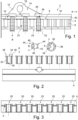
- Fig. 1 shows a fastening system 2 in a schematic, lateral sectional view.
- an elongated floor rail 4 is shown, which has a plurality of spaced-apart receiving openings 6.
- the floor rail 4 could, for example, be integrated into a passenger cabin of an aircraft and then extend parallel to a longitudinal axis x of the aircraft.
- the bottom rail 4 has a top side 8 on which a fitting 10 is arranged. This has a support section 12, which rests flat on the top 8.
- a holding leg 14 extends vertically in a direction facing away from the floor rail 4 and has an eyelet 16 for receiving a bolt or similar for fastening an installation element.
- the support section 12 has a plurality of through holes 18, which here are in alignment with a plurality of receiving openings 6 in the base rail 6.
- the fastening elements 22 have an insertion section 24 which protrudes through the through holes 18 into the receiving openings 6 and thus into the receiving sockets 20.
- the fastening elements 22 also have a shaft section 26 which adjoins the insertion section 24 and is followed by a collar 28. This lies flush on a surface of the support section 12 surrounding the through hole 18.
- the fitting 10 is connected to the floor rail 4 between the fastening elements 22 and a receiving socket 20.
- a fluid-tight, elastic cover element 30, which rests on receiving openings 6, is provided adjacent along the longitudinal extent. It could consist of a rubber-like material and its thickness could be adapted to a thickness of the support section 12.
- a floor covering 32 in the form of a carpet or the like lies on the support section 12 and the cover element 30.
- the cover element 30 protects the receiving openings 6 from contamination and a harmonious, continuous covering of the base rail 4 with the receiving openings 6 is achieved.
- Fig. 2 shows the floor rail 4 in a side view, as well as several receiving sockets 20, each in a side section.
- the receiving bushings 20 each have a fastening opening 34, in which first positive locking means 36 are arranged in the form of first circumferential grooves. These are divided in the circumferential direction into several first segments 38, as shown in a detailed view A.
- the exemplary two first segments 38 each extend over an angle ⁇ of essentially 90° in the circumferential direction.
- a correspondingly shaped fastening element 22 can be inserted directly into the fastening opening 34 in a first relative position in order to produce a positive connection with the first positive locking means 36 by rotating it by approximately 90 °. Free first spaces 40 without first circumferential grooves 36 are provided between the first segments 38 to enable the insertion of fastening elements 22.
- a fastening element 22 is shown, which has second positive locking means in the form of second circumferential grooves 42. These also extend over an angle ⁇ of essentially 90°.
- Two second segments 44 are provided here, which are designed in such a way that the fastening element 22 can be inserted into the receiving socket 20 via the first gaps 40. Free second spaces 46 without further circumferential grooves are provided analogously to the first spaces 40.
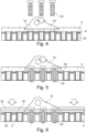
- Figs. 2 and 3 show the insertion of the receiving bushings 20 into the floor rail 4, for example by pressing in, screwing, welding or other types of fastening processes.
- Fig. 4 shows the placement of the fitting 10
- Fig. 5 represents the insertion of the fastening elements 22 into the receiving sockets 20. After rotation of the fastening elements 22 about their longitudinal axis, the cover elements 30 and the floor covering 32 are attached.
- Fig. 7 shows the fastening system 2 in another sectional view, in which the sectional plane runs in the ZY plane.
- a floor 47 is shown as the lower boundary of a passenger cabin, in which the floor rail 4 runs.
- a seat leg 48 is also shown as a built-in element, which is arranged on the fitting 10 with a bolt 50.
- the bottom rail 4 is shown here as an omega-shaped rail, which comprises an upper surface 52, on the underside 54 of which two L-shaped profiles 56 are connected, which are spaced apart from one another and aligned mirror-inverted to one another.
- a vertical leg 58 extends vertically to the top surface 52, while horizontal legs 60 extend parallel thereto and face outwardly. This creates a gap 62 between the profiles 56, which is used Attachment to a floor support 64 or a similar element is adapted.
- a support section 66 is designed as part of a cabin monument and is connected to a monument housing 68.
- Fig. 9 shows a detail of the cover element 30 between individual fastening elements 22.
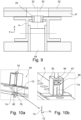
- the 10a and 10b show a fastening system 69 with a differently constructed receiving bushing 70, which is designed as an expanding bushing.
- This has a plurality of circumferential segments 74, each circumferential segment 74 having a free end 76 with a projection 72 arranged thereon.
- the receiving socket 70 can be inserted into one of the receiving openings 6, with a connection between the receiving socket 70 and the receiving opening 6 only taking place by attaching a corresponding fastening element 78.
- the fastening element 78 can, for example, comprise a locking body 80 which locks with the projections 72 from the outside.
- Fig. 10b shows the combination of fastening element 78 and receiving bushing 70 on a fitting 82.
- the fastening element 78 is inserted here into an insertion opening 87 of the expansion bushing 70.
- the fastening element 78 has a circumferential collar 84, which can be brought into abutment with an upper side 86 of the receiving bushing 70 when the receiving bushing 70 is completely arranged in the corresponding receiving opening 6. In this state, the expansion bushing 70 and the fastening element 78 are completely fixed
- FIG. 11a and 11b show a fastening system 89.
- expansion bushing 70 arranged in the floor rail 4
- Fastening element 88 is provided, which can be plugged into the expansion socket 70.
- the fastening element 88 has a foldable eyelet 90 or a fixed eyelet 92, which can be used for lashing cargo in a cargo hold.
- the floor rail 4 is provided here as an example on the floor 47 located above a cargo hold and the fastening element 89 is inserted from below.
- the element 47 can also be a wall paneling and/or upper paneling of a cargo hold and the floor rail 4 can be attached to a floor structure at an upper boundary of the cargo hold.
- This exemplary embodiment can be combined with all previously shown exemplary embodiments.
- Fig. 12 finally shows an aircraft 94, which includes a fuselage 96 with a passenger cabin 98 formed therein, in which a floor 47 is provided.
- the fastening system 2 can be used in the passenger cabin 98 or a cargo hold 100 underneath.
Landscapes
- Engineering & Computer Science (AREA)
- General Engineering & Computer Science (AREA)
- Aviation & Aerospace Engineering (AREA)
- Mechanical Engineering (AREA)
- Connection Of Plates (AREA)
Priority Applications (1)
| Application Number | Priority Date | Filing Date | Title |
|---|---|---|---|
| EP22171054.4A EP4269821A1 (fr) | 2022-04-29 | 2022-04-29 | Système de fixation permettant de fixer un élément encastrable à une structure de plancher dans un véhicule |
Applications Claiming Priority (1)
| Application Number | Priority Date | Filing Date | Title |
|---|---|---|---|
| EP22171054.4A EP4269821A1 (fr) | 2022-04-29 | 2022-04-29 | Système de fixation permettant de fixer un élément encastrable à une structure de plancher dans un véhicule |
Publications (1)
| Publication Number | Publication Date |
|---|---|
| EP4269821A1 true EP4269821A1 (fr) | 2023-11-01 |
Family
ID=81454690
Family Applications (1)
| Application Number | Title | Priority Date | Filing Date |
|---|---|---|---|
| EP22171054.4A Pending EP4269821A1 (fr) | 2022-04-29 | 2022-04-29 | Système de fixation permettant de fixer un élément encastrable à une structure de plancher dans un véhicule |
Country Status (1)
| Country | Link |
|---|---|
| EP (1) | EP4269821A1 (fr) |
Citations (8)
| Publication number | Priority date | Publication date | Assignee | Title |
|---|---|---|---|---|
| EP0151263A2 (fr) * | 1983-12-09 | 1985-08-14 | Norbert L. Piecusch | Elément de fixation |
| FR2686128A1 (fr) * | 1992-01-10 | 1993-07-16 | Hassid Jean Pierre | Systeme d'assemblage rapide de deux elements. |
| DE19960768A1 (de) * | 1999-12-16 | 2001-07-12 | Adelbert Sailer | Fix-Gewinde |
| US20070036629A1 (en) * | 2005-08-10 | 2007-02-15 | Hung-Chin Hsu | Fast fasten and loose resistant bolt and nut structure |
| US20110233339A1 (en) * | 2010-03-23 | 2011-09-29 | Be Aerospace, Inc. | Passenger seat assembly and associated floor panel structure |
| EP3424812A1 (fr) * | 2017-07-06 | 2019-01-09 | The Boeing Company | Système de connexion flottante de panneau de plancher d'aéronef |
| US10457376B1 (en) * | 2012-05-08 | 2019-10-29 | Airmedic | Aircraft stretcher connector |
| US20200086966A1 (en) * | 2018-09-18 | 2020-03-19 | Harper Engineering Co. | Aircraft flooring systems and related methods |
-
2022
- 2022-04-29 EP EP22171054.4A patent/EP4269821A1/fr active Pending
Patent Citations (8)
| Publication number | Priority date | Publication date | Assignee | Title |
|---|---|---|---|---|
| EP0151263A2 (fr) * | 1983-12-09 | 1985-08-14 | Norbert L. Piecusch | Elément de fixation |
| FR2686128A1 (fr) * | 1992-01-10 | 1993-07-16 | Hassid Jean Pierre | Systeme d'assemblage rapide de deux elements. |
| DE19960768A1 (de) * | 1999-12-16 | 2001-07-12 | Adelbert Sailer | Fix-Gewinde |
| US20070036629A1 (en) * | 2005-08-10 | 2007-02-15 | Hung-Chin Hsu | Fast fasten and loose resistant bolt and nut structure |
| US20110233339A1 (en) * | 2010-03-23 | 2011-09-29 | Be Aerospace, Inc. | Passenger seat assembly and associated floor panel structure |
| US10457376B1 (en) * | 2012-05-08 | 2019-10-29 | Airmedic | Aircraft stretcher connector |
| EP3424812A1 (fr) * | 2017-07-06 | 2019-01-09 | The Boeing Company | Système de connexion flottante de panneau de plancher d'aéronef |
| US20200086966A1 (en) * | 2018-09-18 | 2020-03-19 | Harper Engineering Co. | Aircraft flooring systems and related methods |
Similar Documents
| Publication | Publication Date | Title |
|---|---|---|
| DE102015114983B4 (de) | Dachträgerstruktur | |
| EP3561322B1 (fr) | Système de fixation permettant de fixer des éléments de montage dans une cabine de véhicule | |
| DE602005005869T2 (de) | Schnellverschluss zum Befestigen eines Flansches an einer Schiene | |
| DE69912867T2 (de) | Befestigungsvorrichtung für einen Triebwerkträger eines Flugzeuges | |
| AT404926B (de) | Einrichtung zur lösbaren befestigung von abdeckplatten od. dgl. | |
| DE102020108392A1 (de) | Befestigungsvorrichtung und -anordnung zum Befestigen eines Kabineninnenbauteils, Luftfahrzeugkabine und Luftfahrzeug | |
| DE102016111999A1 (de) | Modulares Schienensystem mit Klemmbefestigung | |
| EP2228296B1 (fr) | Sol de soute pour une soute d'avion ainsi que procédé de montage de celui-ci | |
| DE102018103514A1 (de) | Befestigungssystem zum Befestigen von Einbauten an einer Schiene in einem Fahrzeug | |
| EP1336563A2 (fr) | Dispositif de montage pour élément de verrouillage | |
| DE102018123251B4 (de) | Schienensystem zum Befestigen von Einbauten in einer Kabine eines Fahrzeugs | |
| EP3626620A1 (fr) | Module de fixation au sol | |
| DE102015116591A1 (de) | Profil zum Verbinden einer Fußbodenstruktur und Dichtungssystem für eine Fußbodenstruktur | |
| DE102009034414B4 (de) | Befestigungelement und Befestigungsverbund | |
| DE10337746A1 (de) | Sitzbefestigungssystem | |
| DE102016111983B4 (de) | Modulares Schienensystem | |
| EP4269821A1 (fr) | Système de fixation permettant de fixer un élément encastrable à une structure de plancher dans un véhicule | |
| DE102018119846A1 (de) | Flugzeugsitzbefestigungsvorrichtung | |
| DE102021111609A1 (de) | Befestigungsvorrichtung zur lösbaren Verbindung mit einer Lochschiene eines Flugzeugs und Montageverfahren | |
| DE102011012894B4 (de) | Bewegliche Verbindungsplatte zum Verbinden zweier Überkopf-Staufachelemente | |
| DE102016111994A1 (de) | Modulares Schienensystem | |
| EP4067232B1 (fr) | Système de fixation et procédé de fixation permettant de fixer un composant dans une cabine | |
| DE102018101836B4 (de) | Befestigungssystem zum Befestigen von Einbauten in einem Fahrzeug | |
| DE102018126012A1 (de) | Schienenanordnung für einen Innenraum eines Flugzeugs | |
| EP4219304A1 (fr) | Dispositif d'accouplement pour une bielle de liaison |
Legal Events
| Date | Code | Title | Description |
|---|---|---|---|
| PUAI | Public reference made under article 153(3) epc to a published international application that has entered the european phase |
Free format text: ORIGINAL CODE: 0009012 |
|
| STAA | Information on the status of an ep patent application or granted ep patent |
Free format text: STATUS: THE APPLICATION HAS BEEN PUBLISHED |
|
| AK | Designated contracting states |
Kind code of ref document: A1 Designated state(s): AL AT BE BG CH CY CZ DE DK EE ES FI FR GB GR HR HU IE IS IT LI LT LU LV MC MK MT NL NO PL PT RO RS SE SI SK SM TR |
|
| STAA | Information on the status of an ep patent application or granted ep patent |
Free format text: STATUS: REQUEST FOR EXAMINATION WAS MADE |
|
| 17P | Request for examination filed |
Effective date: 20240425 |
|
| RBV | Designated contracting states (corrected) |
Designated state(s): AL AT BE BG CH CY CZ DE DK EE ES FI FR GB GR HR HU IE IS IT LI LT LU LV MC MK MT NL NO PL PT RO RS SE SI SK SM TR |
|
| STAA | Information on the status of an ep patent application or granted ep patent |
Free format text: STATUS: EXAMINATION IS IN PROGRESS |
|
| 17Q | First examination report despatched |
Effective date: 20250225 |