EP4269835A1 - Überlastschlagfestes planetenuntersetzungsgetriebe, robotergelenk und vierbeiniger roboter - Google Patents
Überlastschlagfestes planetenuntersetzungsgetriebe, robotergelenk und vierbeiniger roboter Download PDFInfo
- Publication number
- EP4269835A1 EP4269835A1 EP21909077.6A EP21909077A EP4269835A1 EP 4269835 A1 EP4269835 A1 EP 4269835A1 EP 21909077 A EP21909077 A EP 21909077A EP 4269835 A1 EP4269835 A1 EP 4269835A1
- Authority
- EP
- European Patent Office
- Prior art keywords
- impact
- buffer
- tooth
- overload
- resistant
- Prior art date
- Legal status (The legal status is an assumption and is not a legal conclusion. Google has not performed a legal analysis and makes no representation as to the accuracy of the status listed.)
- Granted
Links
Images


Classifications
-
- F—MECHANICAL ENGINEERING; LIGHTING; HEATING; WEAPONS; BLASTING
- F16—ENGINEERING ELEMENTS AND UNITS; GENERAL MEASURES FOR PRODUCING AND MAINTAINING EFFECTIVE FUNCTIONING OF MACHINES OR INSTALLATIONS; THERMAL INSULATION IN GENERAL
- F16H—GEARING
- F16H35/00—Gearings or mechanisms with other special functional features
- F16H35/10—Arrangements or devices for absorbing overload or preventing damage by overload
-
- F—MECHANICAL ENGINEERING; LIGHTING; HEATING; WEAPONS; BLASTING
- F16—ENGINEERING ELEMENTS AND UNITS; GENERAL MEASURES FOR PRODUCING AND MAINTAINING EFFECTIVE FUNCTIONING OF MACHINES OR INSTALLATIONS; THERMAL INSULATION IN GENERAL
- F16H—GEARING
- F16H1/00—Toothed gearings for conveying rotary motion
- F16H1/28—Toothed gearings for conveying rotary motion with gears having orbital motion
- F16H1/32—Toothed gearings for conveying rotary motion with gears having orbital motion in which the central axis of the gearing lies inside the periphery of an orbital gear
-
- B—PERFORMING OPERATIONS; TRANSPORTING
- B25—HAND TOOLS; PORTABLE POWER-DRIVEN TOOLS; MANIPULATORS
- B25J—MANIPULATORS; CHAMBERS PROVIDED WITH MANIPULATION DEVICES
- B25J9/00—Program-controlled manipulators
- B25J9/10—Program-controlled manipulators characterised by positioning means for manipulator elements
- B25J9/102—Gears specially adapted therefor, e.g. reduction gears
-
- F—MECHANICAL ENGINEERING; LIGHTING; HEATING; WEAPONS; BLASTING
- F16—ENGINEERING ELEMENTS AND UNITS; GENERAL MEASURES FOR PRODUCING AND MAINTAINING EFFECTIVE FUNCTIONING OF MACHINES OR INSTALLATIONS; THERMAL INSULATION IN GENERAL
- F16F—SPRINGS; SHOCK-ABSORBERS; MEANS FOR DAMPING VIBRATION
- F16F15/00—Suppression of vibrations in systems; Means or arrangements for avoiding or reducing out-of-balance forces, e.g. due to motion
- F16F15/10—Suppression of vibrations in rotating systems by making use of members moving with the system
- F16F15/12—Suppression of vibrations in rotating systems by making use of members moving with the system using elastic members or friction-damping members, e.g. between a rotating shaft and a gyratory mass mounted thereon
- F16F15/121—Suppression of vibrations in rotating systems by making use of members moving with the system using elastic members or friction-damping members, e.g. between a rotating shaft and a gyratory mass mounted thereon using springs as elastic members, e.g. metallic springs
- F16F15/124—Elastomeric springs
-
- F—MECHANICAL ENGINEERING; LIGHTING; HEATING; WEAPONS; BLASTING
- F16—ENGINEERING ELEMENTS AND UNITS; GENERAL MEASURES FOR PRODUCING AND MAINTAINING EFFECTIVE FUNCTIONING OF MACHINES OR INSTALLATIONS; THERMAL INSULATION IN GENERAL
- F16F—SPRINGS; SHOCK-ABSORBERS; MEANS FOR DAMPING VIBRATION
- F16F15/00—Suppression of vibrations in systems; Means or arrangements for avoiding or reducing out-of-balance forces, e.g. due to motion
- F16F15/10—Suppression of vibrations in rotating systems by making use of members moving with the system
- F16F15/12—Suppression of vibrations in rotating systems by making use of members moving with the system using elastic members or friction-damping members, e.g. between a rotating shaft and a gyratory mass mounted thereon
- F16F15/121—Suppression of vibrations in rotating systems by making use of members moving with the system using elastic members or friction-damping members, e.g. between a rotating shaft and a gyratory mass mounted thereon using springs as elastic members, e.g. metallic springs
- F16F15/124—Elastomeric springs
- F16F15/126—Elastomeric springs consisting of at least one annular element surrounding the axis of rotation
-
- F—MECHANICAL ENGINEERING; LIGHTING; HEATING; WEAPONS; BLASTING
- F16—ENGINEERING ELEMENTS AND UNITS; GENERAL MEASURES FOR PRODUCING AND MAINTAINING EFFECTIVE FUNCTIONING OF MACHINES OR INSTALLATIONS; THERMAL INSULATION IN GENERAL
- F16H—GEARING
- F16H55/00—Elements with teeth or friction surfaces for conveying motion; Worms, pulleys or sheaves for gearing mechanisms
- F16H55/02—Toothed members; Worms
- F16H55/14—Construction providing resilience or vibration-damping
-
- F—MECHANICAL ENGINEERING; LIGHTING; HEATING; WEAPONS; BLASTING
- F16—ENGINEERING ELEMENTS AND UNITS; GENERAL MEASURES FOR PRODUCING AND MAINTAINING EFFECTIVE FUNCTIONING OF MACHINES OR INSTALLATIONS; THERMAL INSULATION IN GENERAL
- F16H—GEARING
- F16H55/00—Elements with teeth or friction surfaces for conveying motion; Worms, pulleys or sheaves for gearing mechanisms
- F16H55/02—Toothed members; Worms
- F16H55/17—Toothed wheels
-
- F—MECHANICAL ENGINEERING; LIGHTING; HEATING; WEAPONS; BLASTING
- F16—ENGINEERING ELEMENTS AND UNITS; GENERAL MEASURES FOR PRODUCING AND MAINTAINING EFFECTIVE FUNCTIONING OF MACHINES OR INSTALLATIONS; THERMAL INSULATION IN GENERAL
- F16H—GEARING
- F16H57/00—General details of gearing
- F16H57/08—General details of gearing of gearings with members having orbital motion
-
- F—MECHANICAL ENGINEERING; LIGHTING; HEATING; WEAPONS; BLASTING
- F16—ENGINEERING ELEMENTS AND UNITS; GENERAL MEASURES FOR PRODUCING AND MAINTAINING EFFECTIVE FUNCTIONING OF MACHINES OR INSTALLATIONS; THERMAL INSULATION IN GENERAL
- F16H—GEARING
- F16H1/00—Toothed gearings for conveying rotary motion
- F16H1/28—Toothed gearings for conveying rotary motion with gears having orbital motion
- F16H1/2809—Toothed gearings for conveying rotary motion with gears having orbital motion with means for equalising the distribution of load on the planet gears
- F16H1/2836—Toothed gearings for conveying rotary motion with gears having orbital motion with means for equalising the distribution of load on the planet gears by allowing limited movement of the planet gears relative to the planet carrier or by using free floating planet gears
-
- F—MECHANICAL ENGINEERING; LIGHTING; HEATING; WEAPONS; BLASTING
- F16—ENGINEERING ELEMENTS AND UNITS; GENERAL MEASURES FOR PRODUCING AND MAINTAINING EFFECTIVE FUNCTIONING OF MACHINES OR INSTALLATIONS; THERMAL INSULATION IN GENERAL
- F16H—GEARING
- F16H55/00—Elements with teeth or friction surfaces for conveying motion; Worms, pulleys or sheaves for gearing mechanisms
- F16H55/02—Toothed members; Worms
- F16H55/17—Toothed wheels
- F16H2055/176—Ring gears with inner teeth
-
- F—MECHANICAL ENGINEERING; LIGHTING; HEATING; WEAPONS; BLASTING
- F16—ENGINEERING ELEMENTS AND UNITS; GENERAL MEASURES FOR PRODUCING AND MAINTAINING EFFECTIVE FUNCTIONING OF MACHINES OR INSTALLATIONS; THERMAL INSULATION IN GENERAL
- F16H—GEARING
- F16H57/00—General details of gearing
- F16H57/08—General details of gearing of gearings with members having orbital motion
- F16H2057/085—Bearings for orbital gears
Definitions
- the present application relates to an overload impact-resistant planetary reducer, a robot joint, and a quadruped robot, belonging to the technical field of planetary reducers, robot joints and quadruped robots.
- an overload impact protection structure is needed to absorb energy during overload impact, thus protecting transmission components such as gears.
- Chinese patent CN109591045A has disclosed a robot joint unit with high degree-of-integrity and high performance, which includes a motor assembly driving a joint to move, and a reducer assembly.
- the motor assembly includes a motor rotor used for outputting a torque, and a motor base.
- the reducer assembly is provided with a gear ring. The gear ring butts against the motor base under the action of a frictional force generator.
- the gear ring of the reducer assembly will be driven by the output end of the motor rotor or reducer assembly to overcome the frictional torque generated by the frictional force generator, causing the gear ring to rotate relative to the motor base, achieving frictional slipping between the reducer assembly and the motor base, limiting the torque borne by the reducer assembly, and thus preventing the reducer from being damaged due to the large torque from the motor or the output end of the joint unit.
- a first purpose of the present application is to provide an overload impact-resistant planetary reducer including a tooth face portion made of a rigid material and a buffer portion capable of being elastically deformed to form a reducer component capable of preventing overload impact, which is capable of being elastically deformed under an impact force, thus effectively absorbing energy during overload impact and protecting transmission components such as gears.
- the number of parts required is small, the manufacturing cost is low, the occupied space is small and the structure is compact.
- a second purpose of the present application is to provide an overload impact-resistant robot joint including a tooth face portion made of a rigid material and a buffer portion capable of being elastically deformed to form a reducer component capable of preventing overload impact, which is capable of being elastically deformed under an impact force, thus effectively absorbing energy during overload impact and protecting transmission components such as gears.
- the number of parts required is small, the manufacturing cost is low, the occupied space is small and the structure is compact.
- a third purpose of the present application is to provide an overload impact-resistant quadrupled robot including a tooth face portion made of a rigid material and a buffer portion capable of being elastically deformed to form a reducer component capable of preventing overload impact, which is capable of being elastically deformed under an impact force, thus effectively absorbing energy during overload impact and protecting transmission components such as gears.
- the number of parts required is small, the manufacturing cost is low, the occupied space is small and the structure is compact.
- a tooth face portion made of a rigid material and a buffer portion capable of being elastically deformed are provided to form a reducer component capable of preventing overload impact, which is capable of being elastically deformed under an impact force, thus effectively absorbing energy during overload impact and protecting transmission components such as gears.
- the buffer layer is nested on an inner ring side or outer ring side of a bearing between the planetary gear and the planetary gear shaft.
- the buffer layer includes but not limited to rubber, silica gel, plastic and polyurethane, which may be reasonably selected by those skilled in the art according to the actual situation.
- the buffer ring includes but not limited to rubber, silica gel, plastic and polyurethane.
- An overload impact-resistant planetary reducer wherein the overload impact-resistant planetary reducer includes a tooth face portion made of a rigid material and a buffer portion capable of being elastically deformed; the buffer portion is nested with the tooth face portion to form a reducer component capable of preventing overload impact.
- a tooth face portion made of a rigid material and a buffer portion capable of being elastically deformed are provided, and the buffer portion is capable of being elastically deformed under an impact force, thus effectively absorbing energy during overload impact and protecting transmission components such as gears.
- a robot joint wherein the robot joint includes the overload impact-resistant planetary reducer and a motor, and an output shaft of the motor is fixedly connected with a sun gear of the planetary reducer.
- a tooth face portion made of a rigid material and a buffer portion capable of being elastically deformed are provided to form a reducer component capable of preventing overload impact, which is capable of being elastically deformed under an impact force, thus effectively absorbing energy during overload impact and protecting transmission components such as gears.
- a quadrupled robot wherein the quadrupled robot includes the overload impact-resistant planetary reducer.
- a tooth face portion made of a rigid material and a buffer portion capable of being elastically deformed are provided to form a reducer component capable of preventing overload impact, which is capable of being elastically deformed under an impact force, thus effectively absorbing energy during overload impact and protecting transmission components such as gears.
- a tooth face portion made of a rigid material and a buffer portion capable of being elastically deformed are provided to form a reducer component capable of preventing overload impact, which is capable of being elastically deformed under an impact force, thus effectively absorbing energy during overload impact and protecting transmission components such as gears.
- a robot joint having a dynamic sealing structure is provided.
- the robot joint having the dynamic sealing structure includes a power unit housing and an output shaft rotatable relative to the power unit housing.
- the buffer portion is made of a material having certain rigidity and capable of being elastically deformed under an impact force, and is coaxially nested with the tooth face portion to form a reducer component capable of preventing overload impact.
- a tooth face portion made of a rigid material and a buffer portion capable of being elastically deformed are provided to form a reducer component capable of preventing overload impact, which is capable of being elastically deformed under an impact force, thus effectively absorbing energy during overload impact and protecting transmission components such as gears.
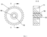
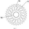
- the reducer component is a planetary gear 21.
- the tooth face portion is an outer tooth portion 11 of the planetary gear 21.
- the buffer portion is a buffer layer 16 assembled on an inner side of the outer tooth portion 11.
- the buffer layer 16 In a case that the outer tooth portion 11 is subjected to an impact force, the buffer layer 16 generates deformation, causing the outer tooth portion 11 to displace relative to the planetary gear shaft 15.
- the buffer layer 16 is provided with at least one deformation through hole 14 capable of being deformed by the impact force.
- the deformation through hole 14 is capable of generating elastic deformation in a case of being subjected to the impact force, so as to further improve the overload impact resistance.
- the buffer layer 16 is nested on an inner ring side or outer ring side of a bearing between the planetary gear 21 and the planetary gear shaft 15.
- the planetary gear shaft 15 is a single-shaft structure or planet carrier 25, which may be selected by those skilled in the art according to the actual situation.
- the buffer layer 16 includes but not limited to rubber, silica gel, plastic and polyurethane, which may be reasonably selected by those skilled in the art according to the actual situation.
- An inner ring portion with a shaft hole is assembled on one side of the buffer layer 16 far away from the outer tooth portion 11.
- the inner ring portion is made of a rigid material.
- the buffer layer 16 In a case that the outer tooth portion 11 is subjected to an overload impact, the buffer layer 16 generates deformation, causing the outer tooth portion 11 and the inner ring portion to rotate and/or displace relative to each other.
- the rigidity of the outer tooth portion 11 and the inner ring portion is greater than the rigidity of the buffer layer 16.
- the buffer layer 16 is respectively screwed, bonded or clamped with the outer tooth portion 11 and the inner ring portion.
- the outer tooth portion 11 and the inner ring portion are made of forged steel, cast steel, or cast iron.
- the buffer layer 16 is made of polyurethane.
- the reducer component is a gear ring.
- the tooth face portion is an inner tooth layer 23 of the gear ring.
- the buffer portion is a buffer ring 24 assembled on an outer side of the inner tooth layer 23.
- the buffer ring 24 In a case that the inner tooth layer 23 is subjected to the impact force, the buffer ring 24 generates tangential deformation, causing the inner tooth layer to displace.
- the buffer ring 24 is provided with at least one deformation through hole 14 capable of being deformed by the impact force.
- the deformation through hole 14 is capable of generating elastic deformation in a case of being subjected to the impact force, so as to improve the overload impact resistance.
- the buffer ring 24 includes but not limited to rubber, silica gel, plastic and polyurethane.
- An outer layer portion 22 is assembled on one side of the buffer ring 24 far away from the inner tooth layer 23.
- the outer layer portion 22 is made of a rigid material.
- the buffer ring 24 In a case that the inner tooth layer 23 is subjected to an overload impact, the buffer ring 24 generates deformation, causing the inner tooth layer 23 to rotate relative to the outer layer portion 22.
- the rigidity of the outer layer portion 22 and the inner tooth layer 23 is greater than the rigidity of the buffer ring 24.
- the buffer ring 24 is respectively screwed, bonded or clamped with the outer layer portion 22 and the inner tooth layer 23.
- the outer layer portion 22 and the inner tooth layer 23 are made of forged steel, cast steel, or cast iron,
- the buffer ring 24 is made of polyurethane.
- a robot joint is provided.
- the robot joint includes the overload impact-resistant planetary reducer and a motor.
- An output shaft of the motor is fixedly connected with a sun gear of the planetary reducer.
- a tooth face portion made of a rigid material and a buffer portion capable of being elastically deformed are provided to form a reducer component capable of preventing overload impact, which is capable of being elastically deformed under an impact force, thus effectively absorbing energy during overload impact and protecting transmission components such as gears.
- a quadrupled robot includes the overload impact-resistant planetary reducer.
- a tooth face portion made of a rigid material and a buffer portion capable of being elastically deformed are provided to form a reducer component capable of preventing overload impact, which is capable of being elastically deformed under an impact force, thus effectively absorbing energy during overload impact and protecting transmission components such as gears.
Landscapes
- Engineering & Computer Science (AREA)
- General Engineering & Computer Science (AREA)
- Mechanical Engineering (AREA)
- Physics & Mathematics (AREA)
- Acoustics & Sound (AREA)
- Aviation & Aerospace Engineering (AREA)
- Robotics (AREA)
- Retarders (AREA)
- Manipulator (AREA)
- Gears, Cams (AREA)
Applications Claiming Priority (2)
| Application Number | Priority Date | Filing Date | Title |
|---|---|---|---|
| CN202011560498.9A CN112728014A (zh) | 2020-12-25 | 2020-12-25 | 一种抗过载冲击的行星减速器及机器人关节和四足机器人 |
| PCT/CN2021/134227 WO2022135078A1 (zh) | 2020-12-25 | 2021-11-30 | 一种抗过载冲击的行星减速器及机器人关节和四足机器人 |
Publications (4)
| Publication Number | Publication Date |
|---|---|
| EP4269835A1 true EP4269835A1 (de) | 2023-11-01 |
| EP4269835A4 EP4269835A4 (de) | 2024-05-22 |
| EP4269835B1 EP4269835B1 (de) | 2025-07-02 |
| EP4269835C0 EP4269835C0 (de) | 2025-07-02 |
Family
ID=75616000
Family Applications (1)
| Application Number | Title | Priority Date | Filing Date |
|---|---|---|---|
| EP21909077.6A Active EP4269835B1 (de) | 2020-12-25 | 2021-11-30 | Überlastschlagfestes planetenuntersetzungsgetriebe, robotergelenk und vierbeiniger roboter |
Country Status (6)
| Country | Link |
|---|---|
| US (1) | US12228201B2 (de) |
| EP (1) | EP4269835B1 (de) |
| JP (1) | JP2023553189A (de) |
| CN (1) | CN112728014A (de) |
| ES (1) | ES3045558T3 (de) |
| WO (1) | WO2022135078A1 (de) |
Families Citing this family (6)
| Publication number | Priority date | Publication date | Assignee | Title |
|---|---|---|---|---|
| CN112728014A (zh) * | 2020-12-25 | 2021-04-30 | 杭州宇树科技有限公司 | 一种抗过载冲击的行星减速器及机器人关节和四足机器人 |
| CN113894837A (zh) * | 2021-10-21 | 2022-01-07 | 杭州宇树科技有限公司 | 一种关节动力单元及应用其的机械臂 |
| ES3009380T3 (en) * | 2021-12-16 | 2025-03-26 | Ims Gear Se & Co Kgaa | Planet gear for a planetary gear transmission and planet carrier for such a planet gear |
| EP4198350A1 (de) * | 2021-12-16 | 2023-06-21 | IMS Gear SE & Co. KGaA | Planetenrad für ein planetengetriebe sowie planetenträger für ein solches planetenrad |
| CN115949701B (zh) * | 2022-12-12 | 2024-09-20 | 江苏东成工具科技有限公司 | 砂磨装置 |
| CN120027186B (zh) * | 2025-02-28 | 2026-01-02 | 奇瑞汽车股份有限公司 | 齿轮、发动机和车辆 |
Family Cites Families (28)
| Publication number | Priority date | Publication date | Assignee | Title |
|---|---|---|---|---|
| DE2057312A1 (de) * | 1970-11-21 | 1972-05-25 | Bhs Bayerische Berg | Planetenradgetriebe mit Lastdruckausgleich |
| GB1448059A (en) * | 1974-04-18 | 1976-09-02 | Vickers Ltd | Gears |
| JP3135562B2 (ja) * | 1990-11-17 | 2001-02-19 | 株式会社日立製作所 | リダクションスタータ |
| EP0551050B1 (de) * | 1992-01-10 | 1996-06-26 | AGINFOR AG für industrielle Forschung | Exzentergetriebe |
| JPH08166050A (ja) * | 1994-12-12 | 1996-06-25 | Mitsubishi Heavy Ind Ltd | 遊星歯車装置 |
| JP2000220699A (ja) * | 1999-02-02 | 2000-08-08 | Olympus Optical Co Ltd | 歯車および駆動力伝達装置 |
| JP2001116115A (ja) * | 1999-10-15 | 2001-04-27 | Nok Corp | 歯車装置 |
| TW580082U (en) * | 2003-06-03 | 2004-03-11 | Jiun-Jie Wang | Improved gear transmission structure |
| JP3706118B2 (ja) * | 2004-01-23 | 2005-10-12 | 川崎重工業株式会社 | 歯車支持構造 |
| JP2009068656A (ja) * | 2007-09-14 | 2009-04-02 | Tigers Polymer Corp | 合成樹脂歯車 |
| CN201531565U (zh) * | 2009-04-02 | 2010-07-21 | 刘兴邦 | 行星齿轮减速装置 |
| JP5888273B2 (ja) * | 2012-08-28 | 2016-03-16 | 株式会社アドヴィックス | 電動パーキングブレーキ用駆動装置 |
| JP2014228015A (ja) * | 2013-05-18 | 2014-12-08 | 株式会社前田精密製作所 | 可撓式歯車 |
| CN103618405A (zh) * | 2013-12-04 | 2014-03-05 | 重庆博耐特实业(集团)有限公司 | 汽车用抗冲击起动电机 |
| CN103867649A (zh) * | 2014-03-17 | 2014-06-18 | 无锡明诚汽车部件有限公司 | 一种具缓冲功能的起动机减速机构 |
| DE102014223473A1 (de) * | 2014-11-18 | 2016-05-19 | Zf Friedrichshafen Ag | Planetenstufe für ein Schwenkmotorgetriebe |
| FR3061524B1 (fr) * | 2017-01-03 | 2019-05-24 | Vianney Rabhi | Rouleau synchronise a roues libres |
| EP3379106B1 (de) * | 2017-03-23 | 2020-10-28 | Cascade Drives AB | Verbundplanetengetriebeanordnung und zahnradanordnung |
| JP6989817B2 (ja) * | 2017-04-05 | 2022-01-12 | ナブテスコ株式会社 | 減速装置 |
| CN207715649U (zh) * | 2017-11-28 | 2018-08-10 | 蚌埠市行星工程机械有限公司 | 能自带阻尼的行星传动装置 |
| CN208767916U (zh) * | 2018-09-27 | 2019-04-19 | 深圳市金顺来特电机有限公司 | 一种行星齿轮减速电机 |
| CN109591045B (zh) | 2018-12-20 | 2025-01-28 | 杭州宇树科技有限公司 | 一种高集成度高性能机器人关节单元 |
| CN110315520B (zh) * | 2019-07-18 | 2022-09-06 | 电子科技大学 | 一种基于变胞机构的能量可控型冗余弹性驱动器 |
| DE102019211451A1 (de) * | 2019-07-31 | 2021-02-04 | Rolls-Royce Deutschland Ltd & Co Kg | Stegzahnrad |
| CN211008305U (zh) * | 2019-10-24 | 2020-07-14 | 山东安舜消防设备有限公司 | 一种减缓防火卷帘门下降速度的制动装置 |
| CN111288125B (zh) * | 2020-02-12 | 2021-03-19 | 常州工学院 | 具有高阻尼高柔性轴承嵌套结构的行星齿轮传动系统 |
| CN111776155A (zh) * | 2020-07-13 | 2020-10-16 | 亳州华弘信息科技有限公司 | 一种半潜式海洋石油钻井平台 |
| CN112728014A (zh) * | 2020-12-25 | 2021-04-30 | 杭州宇树科技有限公司 | 一种抗过载冲击的行星减速器及机器人关节和四足机器人 |
-
2020
- 2020-12-25 CN CN202011560498.9A patent/CN112728014A/zh active Pending
-
2021
- 2021-11-30 EP EP21909077.6A patent/EP4269835B1/de active Active
- 2021-11-30 JP JP2023536022A patent/JP2023553189A/ja active Pending
- 2021-11-30 WO PCT/CN2021/134227 patent/WO2022135078A1/zh not_active Ceased
- 2021-11-30 US US18/269,430 patent/US12228201B2/en active Active
- 2021-11-30 ES ES21909077T patent/ES3045558T3/es active Active
Also Published As
| Publication number | Publication date |
|---|---|
| CN112728014A (zh) | 2021-04-30 |
| US20240133454A1 (en) | 2024-04-25 |
| ES3045558T3 (en) | 2025-11-28 |
| JP2023553189A (ja) | 2023-12-20 |
| EP4269835B1 (de) | 2025-07-02 |
| US12228201B2 (en) | 2025-02-18 |
| EP4269835A4 (de) | 2024-05-22 |
| US20240229909A9 (en) | 2024-07-11 |
| WO2022135078A1 (zh) | 2022-06-30 |
| EP4269835C0 (de) | 2025-07-02 |
Similar Documents
| Publication | Publication Date | Title |
|---|---|---|
| EP4269835B1 (de) | Überlastschlagfestes planetenuntersetzungsgetriebe, robotergelenk und vierbeiniger roboter | |
| EP1712332B1 (de) | Schlagwerkzeug | |
| US20210354292A1 (en) | Highly integrated high-performance robot joint unit | |
| JP6341283B2 (ja) | 打撃工具 | |
| US10250101B2 (en) | Gear stabilization techniques | |
| KR20050086773A (ko) | 표준화 로터리 액튜에이터 | |
| CN106151438B (zh) | 具有过载保护装置的风电齿轮箱 | |
| CN210007541U (zh) | 一种抗超高冲击过载的电机 | |
| CN106625751B (zh) | 一种自锁型关节并联弹性驱动器 | |
| CN110762150A (zh) | 减震器 | |
| CN216666375U (zh) | 一种稳定传动的增程器 | |
| CN104708638A (zh) | 一种具有动量缓冲控制功能的空间机械臂结构 | |
| CN102767592A (zh) | 少齿差啮合式齿轮减速器 | |
| CN206277958U (zh) | 一种增程器连接结构 | |
| EP3152462A1 (de) | Getriebestabilisierungstechniken | |
| CN214274365U (zh) | 一种抗过载冲击的行星减速器及机器人关节和四足机器人 | |
| US11320037B2 (en) | Speed reducer | |
| CN200996300Y (zh) | 平面配流摆线液压马达 | |
| CN113103279A (zh) | 一种机器人关节及机器人 | |
| CN212455373U (zh) | 一种柔性内齿精密行星减速机 | |
| CN117722473A (zh) | 一种兼顾能量回收与能量释放的双差减速器 | |
| CN206159378U (zh) | 一种机械软启动行星减速器 | |
| CN218556912U (zh) | 冲击扳手 | |
| JP5427138B2 (ja) | 衝撃回転工具 | |
| CN215475594U (zh) | 分体式变挡滑套结构及发动机及三轮车 |
Legal Events
| Date | Code | Title | Description |
|---|---|---|---|
| STAA | Information on the status of an ep patent application or granted ep patent |
Free format text: STATUS: THE INTERNATIONAL PUBLICATION HAS BEEN MADE |
|
| PUAI | Public reference made under article 153(3) epc to a published international application that has entered the european phase |
Free format text: ORIGINAL CODE: 0009012 |
|
| STAA | Information on the status of an ep patent application or granted ep patent |
Free format text: STATUS: REQUEST FOR EXAMINATION WAS MADE |
|
| 17P | Request for examination filed |
Effective date: 20230615 |
|
| AK | Designated contracting states |
Kind code of ref document: A1 Designated state(s): AL AT BE BG CH CY CZ DE DK EE ES FI FR GB GR HR HU IE IS IT LI LT LU LV MC MK MT NL NO PL PT RO RS SE SI SK SM TR |
|
| DAV | Request for validation of the european patent (deleted) | ||
| DAX | Request for extension of the european patent (deleted) | ||
| A4 | Supplementary search report drawn up and despatched |
Effective date: 20240423 |
|
| RIC1 | Information provided on ipc code assigned before grant |
Ipc: F16H 55/17 20060101ALI20240417BHEP Ipc: F16H 55/14 20060101ALI20240417BHEP Ipc: F16H 35/10 20060101ALI20240417BHEP Ipc: F16H 1/32 20060101AFI20240417BHEP |
|
| GRAP | Despatch of communication of intention to grant a patent |
Free format text: ORIGINAL CODE: EPIDOSNIGR1 |
|
| STAA | Information on the status of an ep patent application or granted ep patent |
Free format text: STATUS: GRANT OF PATENT IS INTENDED |
|
| INTG | Intention to grant announced |
Effective date: 20250128 |
|
| GRAS | Grant fee paid |
Free format text: ORIGINAL CODE: EPIDOSNIGR3 |
|
| GRAA | (expected) grant |
Free format text: ORIGINAL CODE: 0009210 |
|
| STAA | Information on the status of an ep patent application or granted ep patent |
Free format text: STATUS: THE PATENT HAS BEEN GRANTED |
|
| AK | Designated contracting states |
Kind code of ref document: B1 Designated state(s): AL AT BE BG CH CY CZ DE DK EE ES FI FR GB GR HR HU IE IS IT LI LT LU LV MC MK MT NL NO PL PT RO RS SE SI SK SM TR |
|
| REG | Reference to a national code |
Ref country code: GB Ref legal event code: FG4D |
|
| REG | Reference to a national code |
Ref country code: CH Ref legal event code: EP |
|
| REG | Reference to a national code |
Ref country code: DE Ref legal event code: R096 Ref document number: 602021033595 Country of ref document: DE |
|
| REG | Reference to a national code |
Ref country code: IE Ref legal event code: FG4D |
|
| U01 | Request for unitary effect filed |
Effective date: 20250731 |
|
| U07 | Unitary effect registered |
Designated state(s): AT BE BG DE DK EE FI FR IT LT LU LV MT NL PT RO SE SI Effective date: 20250811 |
|
| U20 | Renewal fee for the european patent with unitary effect paid |
Year of fee payment: 5 Effective date: 20250901 |
|
| REG | Reference to a national code |
Ref country code: ES Ref legal event code: FG2A Ref document number: 3045558 Country of ref document: ES Kind code of ref document: T3 Effective date: 20251128 |
|
| REG | Reference to a national code |
Ref country code: CH Ref legal event code: U11 Free format text: ST27 STATUS EVENT CODE: U-0-0-U10-U11 (AS PROVIDED BY THE NATIONAL OFFICE) Effective date: 20251201 |
|
| PG25 | Lapsed in a contracting state [announced via postgrant information from national office to epo] |
Ref country code: IS Free format text: LAPSE BECAUSE OF FAILURE TO SUBMIT A TRANSLATION OF THE DESCRIPTION OR TO PAY THE FEE WITHIN THE PRESCRIBED TIME-LIMIT Effective date: 20251102 |
|
| PGFP | Annual fee paid to national office [announced via postgrant information from national office to epo] |
Ref country code: GB Payment date: 20251027 Year of fee payment: 5 |
|
| PG25 | Lapsed in a contracting state [announced via postgrant information from national office to epo] |
Ref country code: NO Free format text: LAPSE BECAUSE OF FAILURE TO SUBMIT A TRANSLATION OF THE DESCRIPTION OR TO PAY THE FEE WITHIN THE PRESCRIBED TIME-LIMIT Effective date: 20251002 |
|
| PG25 | Lapsed in a contracting state [announced via postgrant information from national office to epo] |
Ref country code: HR Free format text: LAPSE BECAUSE OF FAILURE TO SUBMIT A TRANSLATION OF THE DESCRIPTION OR TO PAY THE FEE WITHIN THE PRESCRIBED TIME-LIMIT Effective date: 20250702 |
|
| PG25 | Lapsed in a contracting state [announced via postgrant information from national office to epo] |
Ref country code: GR Free format text: LAPSE BECAUSE OF FAILURE TO SUBMIT A TRANSLATION OF THE DESCRIPTION OR TO PAY THE FEE WITHIN THE PRESCRIBED TIME-LIMIT Effective date: 20251003 |
|
| PGFP | Annual fee paid to national office [announced via postgrant information from national office to epo] |
Ref country code: CH Payment date: 20251201 Year of fee payment: 5 |
|
| PG25 | Lapsed in a contracting state [announced via postgrant information from national office to epo] |
Ref country code: CZ Free format text: LAPSE BECAUSE OF FAILURE TO SUBMIT A TRANSLATION OF THE DESCRIPTION OR TO PAY THE FEE WITHIN THE PRESCRIBED TIME-LIMIT Effective date: 20250702 |
|
| PGFP | Annual fee paid to national office [announced via postgrant information from national office to epo] |
Ref country code: IE Payment date: 20251127 Year of fee payment: 5 |
|
| PG25 | Lapsed in a contracting state [announced via postgrant information from national office to epo] |
Ref country code: PL Free format text: LAPSE BECAUSE OF FAILURE TO SUBMIT A TRANSLATION OF THE DESCRIPTION OR TO PAY THE FEE WITHIN THE PRESCRIBED TIME-LIMIT Effective date: 20250702 |
|
| PG25 | Lapsed in a contracting state [announced via postgrant information from national office to epo] |
Ref country code: RS Free format text: LAPSE BECAUSE OF FAILURE TO SUBMIT A TRANSLATION OF THE DESCRIPTION OR TO PAY THE FEE WITHIN THE PRESCRIBED TIME-LIMIT Effective date: 20251002 |
|
| PGFP | Annual fee paid to national office [announced via postgrant information from national office to epo] |
Ref country code: ES Payment date: 20251202 Year of fee payment: 5 |
|
| PG25 | Lapsed in a contracting state [announced via postgrant information from national office to epo] |
Ref country code: SM Free format text: LAPSE BECAUSE OF FAILURE TO SUBMIT A TRANSLATION OF THE DESCRIPTION OR TO PAY THE FEE WITHIN THE PRESCRIBED TIME-LIMIT Effective date: 20250702 |
|
| PG25 | Lapsed in a contracting state [announced via postgrant information from national office to epo] |
Ref country code: SK Free format text: LAPSE BECAUSE OF FAILURE TO SUBMIT A TRANSLATION OF THE DESCRIPTION OR TO PAY THE FEE WITHIN THE PRESCRIBED TIME-LIMIT Effective date: 20250702 |