EP4269839A1 - Système d'étanchéité autocompensateur à dilatation thermique pour réacteur cylindrique rotatif - Google Patents
Système d'étanchéité autocompensateur à dilatation thermique pour réacteur cylindrique rotatif Download PDFInfo
- Publication number
- EP4269839A1 EP4269839A1 EP21870615.8A EP21870615A EP4269839A1 EP 4269839 A1 EP4269839 A1 EP 4269839A1 EP 21870615 A EP21870615 A EP 21870615A EP 4269839 A1 EP4269839 A1 EP 4269839A1
- Authority
- EP
- European Patent Office
- Prior art keywords
- ring
- cylindrical rotating
- self
- rotating reactor
- bearing race
- Prior art date
- Legal status (The legal status is an assumption and is not a legal conclusion. Google has not performed a legal analysis and makes no representation as to the accuracy of the status listed.)
- Granted
Links
Images


Classifications
-
- F—MECHANICAL ENGINEERING; LIGHTING; HEATING; WEAPONS; BLASTING
- F16—ENGINEERING ELEMENTS AND UNITS; GENERAL MEASURES FOR PRODUCING AND MAINTAINING EFFECTIVE FUNCTIONING OF MACHINES OR INSTALLATIONS; THERMAL INSULATION IN GENERAL
- F16J—PISTONS; CYLINDERS; SEALINGS
- F16J15/00—Sealings
- F16J15/16—Sealings between relatively-moving surfaces
- F16J15/164—Sealings between relatively-moving surfaces the sealing action depending on movements; pressure difference, temperature or presence of leaking fluid
-
- F—MECHANICAL ENGINEERING; LIGHTING; HEATING; WEAPONS; BLASTING
- F27—FURNACES; KILNS; OVENS; RETORTS
- F27B—FURNACES, KILNS, OVENS OR RETORTS IN GENERAL; OPEN SINTERING OR LIKE APPARATUS
- F27B7/00—Rotary-drum furnaces, i.e. horizontal or slightly inclined
- F27B7/20—Details, accessories or equipment specially adapted for rotary-drum furnaces
- F27B7/22—Rotary drums; Supports therefor
- F27B7/24—Seals between rotary and stationary parts
-
- B—PERFORMING OPERATIONS; TRANSPORTING
- B01—PHYSICAL OR CHEMICAL PROCESSES OR APPARATUS IN GENERAL
- B01J—CHEMICAL OR PHYSICAL PROCESSES, e.g. CATALYSIS OR COLLOID CHEMISTRY; THEIR RELEVANT APPARATUS
- B01J8/00—Chemical or physical processes in general, conducted in the presence of fluids and solid particles; Apparatus for such processes
- B01J8/08—Chemical or physical processes in general, conducted in the presence of fluids and solid particles; Apparatus for such processes with moving particles
- B01J8/10—Chemical or physical processes in general, conducted in the presence of fluids and solid particles; Apparatus for such processes with moving particles moved by stirrers or by rotary drums or rotary receptacles or endless belts
-
- F—MECHANICAL ENGINEERING; LIGHTING; HEATING; WEAPONS; BLASTING
- F16—ENGINEERING ELEMENTS AND UNITS; GENERAL MEASURES FOR PRODUCING AND MAINTAINING EFFECTIVE FUNCTIONING OF MACHINES OR INSTALLATIONS; THERMAL INSULATION IN GENERAL
- F16J—PISTONS; CYLINDERS; SEALINGS
- F16J15/00—Sealings
- F16J15/16—Sealings between relatively-moving surfaces
- F16J15/32—Sealings between relatively-moving surfaces with elastic sealings, e.g. O-rings
-
- F—MECHANICAL ENGINEERING; LIGHTING; HEATING; WEAPONS; BLASTING
- F23—COMBUSTION APPARATUS; COMBUSTION PROCESSES
- F23G—CREMATION FURNACES; CONSUMING WASTE PRODUCTS BY COMBUSTION
- F23G5/00—Incineration of waste; Incinerator constructions; Details, accessories or control therefor
- F23G5/44—Details; Accessories
-
- B—PERFORMING OPERATIONS; TRANSPORTING
- B01—PHYSICAL OR CHEMICAL PROCESSES OR APPARATUS IN GENERAL
- B01J—CHEMICAL OR PHYSICAL PROCESSES, e.g. CATALYSIS OR COLLOID CHEMISTRY; THEIR RELEVANT APPARATUS
- B01J19/00—Chemical, physical or physico-chemical processes in general; Their relevant apparatus
- B01J19/0053—Details of the reactor
- B01J19/0073—Sealings
Definitions
- the present invention relates to thermal expansion self-compensating systems.
- a self-compensating thermal expansion system in cylindrical rotating reactors in particular, to a self-compensating thermal expansion system in cylindrical rotating reactors.
- cylindrical rotating reactors are the drying of organic matter and food, biomass roasting and pyrolysis, and the treatment of mineral coals.
- these processes require hermetic reactors, with a sealing system that prevents the entry of atmospheric air or the unintentional escape of reactant gases.
- it is difficult to seal it, taking into account the thermal expansion of the reactor and the fact that it has moving parts.
- Document BR112013008504-5 B1 describes a biomass torrefaction system comprising: (i) an inlet to receive the biomass particles; (ii) a reactor drum configured to rotate about an axis of rotation, the reactor drum having a plurality of vanes positioned therein at a plurality of locations along a longitudinal length of the reactor drum, the vanes disposed within the drum at selected positions and density to improve the characteristics of particles resulting from biomass subjected to torrefaction; (iii) a heat source upstream of the drum reactor to heat the gas contained in the system to a temperature sufficient to roast the biomass particles during operation; (iv) a fan device coupled to the system to create, when the system is in operation, a stream of heated gas through the drum reactor sufficient to intermittently transport the biomass particles along the longitudinal length of the drum reactor as the biomass particles are lifted through the vanes and poured through the stream of heated gas, while the drum reactor rotates; (v) and gas pipelines coupled to at least the drum reactor, heat source and blower device for re
- Document US20090007484 A1 describes an apparatus and a process for producing carbonaceous and/or hydrocarbon materials from a biomass composition, the apparatus including: (i) a charge port; (ii) a thermal decomposition assembly including a reactor comprising an inner hollow cylinder, an outer hollow cylinder, one of which is rotatable with respect to the other, both heated hollow cylinders supplying heat to the feed composition to convert it into a vapor fraction and a solid residue fraction; (iii) vanes mounted relative to the inner and outer hollow cylinders to move the biomass composition through the thermal decomposition assembly; (iv) at least one steam port to remove the steam fraction containing a hydrocarbon material; (v) and at least one solids gate to remove the solid fraction, containing a carbonaceous material.
- a charge port including a reactor comprising an inner hollow cylinder, an outer hollow cylinder, one of which is rotatable with respect to the other, both heated hollow cylinders supplying heat to the feed composition to convert it into a vapor fraction
- Document US20030202756 A1 discloses a rotating heat treatment drum with a toothed edge arranged in the drum housing and supported at various peripheral points in the drum housing by evenly distributed bridge members.
- Each bridge member includes two clips spaced axially apart from each other and welded to the drum shell, and a cross plate that connects the clips and is radially away from the drum shell.
- Each cross plate is rigidly connected to one clip and slidably connected in the axial direction to the other clip, so that different degrees of thermal expansion and consequent deformation of the cross plates and increased stress on the cross plates, clips, and connection points can be compensated for.
- Document US20030202756 A1 does not address the issue of ensuring gas sealing to prevent ingress or egress from the rotating drum.
- Document US5890814 A describes a rotating drum arrangement, in which the drum is mounted on support rings so that circumferential expansion and contraction of the drum relative to said support rings does not adversely affect the assembly.
- the drum blocks are mounted on the drum and the corresponding ring blocks are mounted on the support ring.
- the side surfaces of adjacent drum blocks and ring blocks support the weight of the drum in the ring.
- gaps can be maintained between the drum and the support ring to allow for expansion and contraction of the drum.
- the issue of rotating drum tightness is not discussed.
- the present invention aims at solving the problems mentioned above, since there is not a self-compensating thermal expansion system in the state of the art that is adapted to a cylindrical rotating reactor, which ensures the sealing between the moving and stationary parts of the equipment, and, therefore, the hermeticity of the reaction means, with a wide range of working temperatures, which ends up generating large expansion variations.
- the main objective of the present invention is to provide a self-compensating thermal expansion sealing system for a wide temperature range cylindrical rotating reactor, allowing higher thermal expansions when compared to the prior state of art
- the present invention provides a self-compensating thermal expansion sealing system for a cylindrical rotating reactor comprising (a) a first self-compensating portion positioned at a first end of the cylindrical rotating reactor, the first self-compensating portion comprising (a.
- a cylindrical rotating reactor 2 is defined as a cylindrical rotating body with openings at its ends.
- the system of the present invention comprises a first self-compensating portion 8 positioned at a first end of the cylindrical rotating reactor 2, and a second self-compensating portion 9 positioned at a second end of the rotating cylindrical reactor 2, the second end of the rotating cylindrical reactor 2 being opposite of the first end.
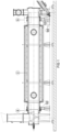
- the first self-compensating portion 8 further comprises a first ring-shaped bearing race 22 fixed to the housing of the cylindrical rotating reactor 2 and supported on a first support roller 32 which is responsible for slidably and rotationally supporting the first end of the rotating cylindrical reactor 2, as shown in Figure 1 .
- the second self-compensating portion 9 further comprises a first ring-shaped bearing race 23 attached to the housing of the cylindrical rotating reactor 2 and supported on a first support roller 33 that is responsible for slidably and rotationally supporting the first end of the rotating cylindrical reactor 2.
- bearing race 23 has a cellar represented by the number 23a, in distinction from runway 22 which is smooth.
- the bearing roller 33 is housed. In this way, no axial displacement is allowed to the bearing race 23 and the expansion (or contraction) of the cylindrical rotating reactor 2, due to the heating (or cooling) thereof, is fully transferred to the self-compensating portion 8, causing the bearing roller 32 to slide axially on the bearing race 22.
- the first self-compensating portion 8 comprises a guide ring 80 attached to the support structure of the cylindrical rotating reactor 2.
- the guide ring 80 is a stationary ring.
- the first portion of self-compensating 8 also comprises an axially sliding housing ring 84 surrounding the guide ring 80, the axially sliding housing ring 84 being axially sliding with respect to the guide ring 80 and rotationally stationary with respect to the cylindrical rotating reactor.
- the fact that the axially sliding housing ring 84 is movable in the axial direction with respect to the guide ring 80 allows axial dilatation compensation of the cylindrical rotating reactor 2.
- the axially sliding housing ring 84 houses a first dancing roller 85, in which at least one first side seal gasket 86 is installed.
- the second self-compensating portion 9 also comprises a housing ring, but this is a fixed housing ring 94, which in turn houses a second dancing roller 85', into which is fitted at least a second side seal 86' .
- the first bearing race 22 is sliding in the radial direction with respect to the axially sliding housing ring 84 and sympathetic to it in the axial direction of the cylindrical rotating reactor 2.
- the first bearing race 22 pushes the axially sliding housing ring 84 in the opposite direction to the second self-compensating portion 9.
- a track roller 88 attached to the upper portion of the axially sliding housing ring 84 by means of a track roller support 87 is responsible for solidifying the movement of the first bearing race 22 with that of the axially sliding housing ring 84.
- the first bearing race 22 "pulls" the axially sliding housing ring 84 toward the second self-compensating portion 9 by means of the guiding roller 88 and its respective guiding roller support 87.
- the guiding roller 88 contacts a lateral surface of a recess of the first bearing raceway 22 and predisposes said axially sliding housing ring 84 towards the first bearing race 22.
- a plurality of guiding rollers 88 and guiding roller supports 87 are provided along the circumference of the axially sliding housing ring 84.
- the first portion of self-commissioning 8 comprises additionally a first dancing roller 85 lodged with a side cavity of the axially sliding axial housing ring 84, the first dancing roller 85 being predisposed in the direction of a lateral face of the bearing race 22 by means of at least one elastic element. More preferably, at least one first side gasket 86 compressed between the first dancing roller 85 and the side face of the first bearing race 22 is provided.
- the dancing roller 85 is stationary and there is a dimensional gap between it and the side cavity of the axially sliding housing ring 84 where it is inserted. This clearance allows the first dancing roller 85 to move and absorb any angular misalignment between the axis of the cylindrical rotating reactor 2 and the axis of its support structure.
- the at least one elastic element is at least a first pin roll 83. Still preferably, a plurality of first pin rolls 83 are provided along the circumference of the axially sliding housing ring 84.
- the first self-compensating portion 8 additionally comprises at least one lower gasket 82 compressed between the axially sliding housing ring 84 and the upper face of the guide ring 80.
- a pressure ring 81 attached to the axially sliding housing ring 84 through screws is provided to adjust the pressure of the at least one lower gasket 82.
- the second portion of self-compensating 9 is positioned at a second end of the cylindrical rotating reactor 2, opposite to the first.
- the second self-compensating portion 9 comprises a fixed housing ring 94 to the support structure of the cylindrical rotating reactor 2.
- the second self-compensating portion 9 further comprises a second ring-shaped bearing race 23 attached to the housing of the cylindrical rotating reactor 2 and supported on a second support roller 33 which is responsible for rotatably supporting the second end of the cylindrical rotating reactor 2, as shown in Figure 1 .
- the second bearing race 23 preferably comprises a cellar 23a adapted to fit the respective second support roller 33.
- the second support roller 33 works within this cellar 23a, so that it prevents the bearing race 23 from moving in the direction axial to the cylindrical rotating reactor 2. All axial displacement due to the increased length of the rotating body is directed to the first portion of self-compensating 8. Since in the preferred embodiment of the present invention the first bearing race 22 does not have an equivalent recess, the first support roller 32 is allowed to slip axially along the first bearing race 22 whenever the rotating body is heated or cooled.
- the second self-compensating portion 9 further comprises a second dancing roller 85' loosely housed in a lateral cavity of the fixed housing ring 94, the second dancing roller 85' being predisposed towards a lateral face of the second bearing race 23 by means of at least a second elastic element. More preferably, at least a second side gasket 86' compressed between the second dancing roller 85' and the side face of the second bearing race 23 is provided.
- the second dancer rolling 85 ' is preferably identical to the first dancer rolling 85 described above, in order to move and absorb any angular misalignment between the axis of the cylindrical rotating reactor 2 and the axis of its support structure.
- the at least one elastic element is at least a second pin roll 83'. Still preferably, a plurality of second pin rolls 83' are provided along the circumference of the fixed housing ring 94.
- first 22 and second 23 bearing races are attached to the surface of the cylindrical rotating reactor 2 by screwing into at least one ring 21 attached to the surface of the cylindrical rotating reactor 2, as shown in Figures 2 and 3 .
- first 22 and second 23 bearing races are attached to the surface of the cylindrical rotating reactor 2 by welding on at least one centering ring 21 attached to the surface of the cylindrical rotating reactor 2 (not shown).
- first 22 and second 23 bearing races are attached to the surface of the cylindrical rotating reactor 2 by direct welding to the surface of the cylindrical rotating reactor 2 (not shown).
- first 22 and second 23 bearing races are attached to the surface of the cylindrical rotating reactor 2 by direct screwing to the surface of the cylindrical rotating reactor 2 (not shown).
- the cylindrical rotating reactor 2 is driven by a motor 50 whose shaft comprises at least one gear (not shown) engaged to a ring gear 90 attached to one of the bearing races 22, 23. More preferably, the ring-shaped gear 90 is attached to the second bearing race 23.
- the present invention provides a self-compensating thermal expansion sealing system for a wide temperature spectrum cylindrical rotating reactor, allowing higher thermal expansions when compared to the prior state of art.
Landscapes
- Engineering & Computer Science (AREA)
- General Engineering & Computer Science (AREA)
- Mechanical Engineering (AREA)
- Chemical & Material Sciences (AREA)
- Organic Chemistry (AREA)
- Chemical Kinetics & Catalysis (AREA)
- Muffle Furnaces And Rotary Kilns (AREA)
- Sealing Devices (AREA)
- Physical Or Chemical Processes And Apparatus (AREA)
- Accessories Of Cameras (AREA)
- Mechanical Sealing (AREA)
- Mounting Of Bearings Or Others (AREA)
Applications Claiming Priority (2)
| Application Number | Priority Date | Filing Date | Title |
|---|---|---|---|
| BR102020019375-9A BR102020019375B1 (pt) | 2020-09-24 | 2020-09-24 | Sistema de vedação autocompensador de dilatação térmica para um reator cilíndrico rotativo |
| PCT/BR2021/050397 WO2022061434A1 (fr) | 2020-09-24 | 2021-09-17 | Système d'étanchéité autocompensateur à dilatation thermique pour réacteur cylindrique rotatif |
Publications (4)
| Publication Number | Publication Date |
|---|---|
| EP4269839A1 true EP4269839A1 (fr) | 2023-11-01 |
| EP4269839A4 EP4269839A4 (fr) | 2025-01-15 |
| EP4269839B1 EP4269839B1 (fr) | 2025-11-26 |
| EP4269839C0 EP4269839C0 (fr) | 2025-11-26 |
Family
ID=80844468
Family Applications (1)
| Application Number | Title | Priority Date | Filing Date |
|---|---|---|---|
| EP21870615.8A Active EP4269839B1 (fr) | 2020-09-24 | 2021-09-17 | Système d'étanchéité autocompensateur à dilatation thermique pour réacteur cylindrique rotatif |
Country Status (13)
| Country | Link |
|---|---|
| US (1) | US12560380B2 (fr) |
| EP (1) | EP4269839B1 (fr) |
| JP (1) | JP2023542217A (fr) |
| KR (1) | KR20230073249A (fr) |
| CN (1) | CN116249850B (fr) |
| AR (1) | AR123596A1 (fr) |
| BR (1) | BR102020019375B1 (fr) |
| CA (1) | CA3192674A1 (fr) |
| CL (1) | CL2023000850A1 (fr) |
| PY (1) | PY2183102A (fr) |
| UY (1) | UY39433A (fr) |
| WO (1) | WO2022061434A1 (fr) |
| ZA (1) | ZA202304652B (fr) |
Families Citing this family (1)
| Publication number | Priority date | Publication date | Assignee | Title |
|---|---|---|---|---|
| BR102020019375B1 (pt) | 2020-09-24 | 2022-07-12 | Tecnored Desenvolvimento Tecnologico S.A. | Sistema de vedação autocompensador de dilatação térmica para um reator cilíndrico rotativo |
Family Cites Families (29)
| Publication number | Priority date | Publication date | Assignee | Title |
|---|---|---|---|---|
| US2702218A (en) * | 1952-10-17 | 1955-02-15 | Monolith Portland Cement Compa | Means for mounting circular rails on rotary mills |
| DE1273268B (de) * | 1966-01-04 | 1968-07-18 | Polysius Gmbh | Drehtrommel-Laufringbefestigung |
| DE2741738C3 (de) * | 1977-09-16 | 1981-04-02 | Smit Ovens Nijmegen B.V., Nijmegen | Stirn-Mantelgleitdichtung zwischen einer ortsfesten Haube und einem Drehrohrofenende |
| US4209175A (en) * | 1979-02-09 | 1980-06-24 | Allis-Chalmers Corporation | Articulated seal for rotating cylinder such as kiln or the like |
| BR7907438A (pt) * | 1979-11-14 | 1981-05-19 | Tosco Corp | Forno rotativo, conjunto de vedacao e processo de proporcionar uma vedacao hermetica a fluidos |
| JPS595826Y2 (ja) * | 1981-10-24 | 1984-02-22 | 川崎重工業株式会社 | 回転筒のシ−ル装置 |
| AT397861B (de) * | 1990-09-04 | 1994-07-25 | Ragailler Roland Mag | Drehofen, insbesondere zur pyrolyse von abfallprodukten |
| US5106105A (en) * | 1990-10-17 | 1992-04-21 | United States Department Of Energy | Rotary kiln seal |
| US5174750A (en) * | 1991-05-30 | 1992-12-29 | Westinghouse Electric Corp. | Circumferential seal system for a rotary combustor |
| IT1267428B1 (it) * | 1994-03-18 | 1997-02-05 | Skf Ind Spa | Dispositivo di tenuta per cuscinetti volventi. |
| DE19623577C2 (de) * | 1996-06-13 | 1998-04-30 | Krc Umwelttechnik Gmbh | Dichtung für Drehrohre |
| US5890814A (en) | 1997-09-03 | 1999-04-06 | Gentec, Inc. | Support ring mount for rotating drum |
| US6563990B1 (en) | 1998-06-22 | 2003-05-13 | Corning Cable Systems, Llc | Self-supporting cables and an apparatus and methods for making the same |
| JP2001116460A (ja) * | 1999-10-18 | 2001-04-27 | Toshiba Corp | 回転炉のシール装置 |
| JP2001304763A (ja) * | 2000-04-21 | 2001-10-31 | Meidensha Corp | 回転加熱処理装置 |
| DE102004031020B4 (de) * | 2004-06-26 | 2019-11-14 | Solvay Fluor Gmbh | Dichtungsanordnung |
| US7686612B1 (en) * | 2006-12-28 | 2010-03-30 | Barry Buteau | Rotary kiln seal |
| US20090007484A1 (en) | 2007-02-23 | 2009-01-08 | Smith David G | Apparatus and process for converting biomass feed materials into reusable carbonaceous and hydrocarbon products |
| EE01022U1 (et) * | 2009-12-11 | 2011-04-15 | Eesti Energia ?litööstus AS | Trummelreaktori otstihenduss?lm |
| US8246788B2 (en) | 2010-10-08 | 2012-08-21 | Teal Sales Incorporated | Biomass torrefaction system and method |
| CN201922205U (zh) * | 2010-12-01 | 2011-08-10 | 安徽星马汽车股份有限公司 | 混凝土搅拌车筒体滚道焊接用翻转连接装置 |
| CN106482506B (zh) * | 2016-12-12 | 2019-12-03 | 朱书红 | 旋转密封机构 |
| CN107966262B (zh) * | 2017-11-20 | 2019-07-12 | 北京航天长征飞行器研究所 | 一种带有滑动热补偿功能的高温真空风洞试验舱和扩压器整体结构及滑动热补偿方法 |
| CN208936753U (zh) * | 2018-06-26 | 2019-06-04 | 湖南万容科技股份有限公司 | 一种回转窑伸缩机构 |
| DE102018133566A1 (de) * | 2018-12-21 | 2020-06-25 | Eisenmann Se | Drehrohrofen |
| CN111486280A (zh) * | 2019-01-29 | 2020-08-04 | 中国石油化工股份有限公司 | 可自由伸缩式地面内衬管线由壬连接接头 |
| CN209974567U (zh) * | 2019-03-04 | 2020-01-21 | 江苏五水环境工程有限公司当阳分公司 | 一种新型双保险玻璃钢化粪池 |
| CN209820388U (zh) * | 2019-04-16 | 2019-12-20 | 江苏鸿承机电设备有限公司 | 一种补偿器测试装置 |
| BR102020019375B1 (pt) | 2020-09-24 | 2022-07-12 | Tecnored Desenvolvimento Tecnologico S.A. | Sistema de vedação autocompensador de dilatação térmica para um reator cilíndrico rotativo |
-
2020
- 2020-09-24 BR BR102020019375-9A patent/BR102020019375B1/pt active IP Right Grant
-
2021
- 2021-09-17 WO PCT/BR2021/050397 patent/WO2022061434A1/fr not_active Ceased
- 2021-09-17 CN CN202180064375.2A patent/CN116249850B/zh active Active
- 2021-09-17 KR KR1020237012579A patent/KR20230073249A/ko active Pending
- 2021-09-17 EP EP21870615.8A patent/EP4269839B1/fr active Active
- 2021-09-17 JP JP2023518418A patent/JP2023542217A/ja active Pending
- 2021-09-17 US US18/027,957 patent/US12560380B2/en active Active
- 2021-09-17 CA CA3192674A patent/CA3192674A1/fr active Pending
- 2021-09-22 PY PY202102183102A patent/PY2183102A/es unknown
- 2021-09-23 UY UY0001039433A patent/UY39433A/es unknown
- 2021-09-24 AR ARP210102657A patent/AR123596A1/es active IP Right Grant
-
2023
- 2023-03-23 CL CL2023000850A patent/CL2023000850A1/es unknown
- 2023-04-21 ZA ZA2023/04652A patent/ZA202304652B/en unknown
Also Published As
| Publication number | Publication date |
|---|---|
| US20230366625A1 (en) | 2023-11-16 |
| KR20230073249A (ko) | 2023-05-25 |
| CA3192674A1 (fr) | 2022-03-31 |
| BR102020019375A2 (pt) | 2022-04-05 |
| JP2023542217A (ja) | 2023-10-05 |
| EP4269839B1 (fr) | 2025-11-26 |
| CL2023000850A1 (es) | 2023-11-03 |
| CN116249850B (zh) | 2026-03-17 |
| ZA202304652B (en) | 2025-08-27 |
| UY39433A (es) | 2022-02-25 |
| US12560380B2 (en) | 2026-02-24 |
| EP4269839A4 (fr) | 2025-01-15 |
| WO2022061434A1 (fr) | 2022-03-31 |
| AR123596A1 (es) | 2022-12-21 |
| BR102020019375B1 (pt) | 2022-07-12 |
| EP4269839C0 (fr) | 2025-11-26 |
| PY2183102A (es) | 2022-09-14 |
| CN116249850A (zh) | 2023-06-09 |
Similar Documents
| Publication | Publication Date | Title |
|---|---|---|
| US4199154A (en) | Labyrinth sealing system | |
| US11959704B2 (en) | Rotary tube kiln | |
| US4589354A (en) | Apparatus for the recovery of gases from waste materials | |
| EP3553439B1 (fr) | Mécanisme d'étanchéité rotatif | |
| EP3050939A1 (fr) | Four de carbonisation chauffé de façon externe | |
| US12560380B2 (en) | Sealing system with automatic compensation for thermal expansion for a rotary cylindrical reactor | |
| CA1326357C (fr) | Four rotatif | |
| US4502702A (en) | Segmented seal for rotary equipment | |
| JP7261688B2 (ja) | 連続式加熱処理装置 | |
| CN202989059U (zh) | 旋转加热装置 | |
| CN204779473U (zh) | 一种防粉尘的煤热解提质回转炉 | |
| US3575397A (en) | Kiln seal | |
| CA1087838A (fr) | Four rotatif | |
| EA021453B1 (ru) | Торцевой уплотнительный узел вращающейся печи | |
| GB2583748A (en) | Rotary seal and bearing | |
| US3477704A (en) | Connection apparatus for sections of a rotary furnace | |
| US3560005A (en) | Seal for a rotating chamber | |
| JP4599778B2 (ja) | 加熱用ドラムのシール | |
| US3978914A (en) | Rotary ceramic heat exchanger mounting | |
| JP2008256288A (ja) | ロータリーキルンのシール装置 | |
| GB2129533A (en) | Rotary regenerative heat exchanger | |
| US3464683A (en) | Rotary retort furnace | |
| JPS5833519Y2 (ja) | 回転炉 | |
| JP2022124545A (ja) | 回転円筒炉の炉内ガスの流出及び外気の炉内流入を阻止する装置構造 | |
| US3978913A (en) | Incinerator and heat exchanger structure therefor |
Legal Events
| Date | Code | Title | Description |
|---|---|---|---|
| STAA | Information on the status of an ep patent application or granted ep patent |
Free format text: STATUS: THE INTERNATIONAL PUBLICATION HAS BEEN MADE |
|
| PUAI | Public reference made under article 153(3) epc to a published international application that has entered the european phase |
Free format text: ORIGINAL CODE: 0009012 |
|
| STAA | Information on the status of an ep patent application or granted ep patent |
Free format text: STATUS: REQUEST FOR EXAMINATION WAS MADE |
|
| 17P | Request for examination filed |
Effective date: 20230324 |
|
| AK | Designated contracting states |
Kind code of ref document: A1 Designated state(s): AL AT BE BG CH CY CZ DE DK EE ES FI FR GB GR HR HU IE IS IT LI LT LU LV MC MK MT NL NO PL PT RO RS SE SI SK SM TR |
|
| DAV | Request for validation of the european patent (deleted) | ||
| DAX | Request for extension of the european patent (deleted) | ||
| A4 | Supplementary search report drawn up and despatched |
Effective date: 20241216 |
|
| RIC1 | Information provided on ipc code assigned before grant |
Ipc: B01J 19/00 20060101ALN20241210BHEP Ipc: B01J 8/10 20060101ALI20241210BHEP Ipc: F27B 7/24 20060101ALI20241210BHEP Ipc: F16J 15/32 20160101ALI20241210BHEP Ipc: F16J 15/16 20060101AFI20241210BHEP |
|
| GRAP | Despatch of communication of intention to grant a patent |
Free format text: ORIGINAL CODE: EPIDOSNIGR1 |
|
| STAA | Information on the status of an ep patent application or granted ep patent |
Free format text: STATUS: GRANT OF PATENT IS INTENDED |
|
| RIC1 | Information provided on ipc code assigned before grant |
Ipc: F16J 15/16 20060101AFI20250716BHEP Ipc: F16J 15/32 20160101ALI20250716BHEP Ipc: F27B 7/24 20060101ALI20250716BHEP Ipc: B01J 8/10 20060101ALI20250716BHEP Ipc: B01J 19/00 20060101ALN20250716BHEP |
|
| INTG | Intention to grant announced |
Effective date: 20250723 |
|
| GRAS | Grant fee paid |
Free format text: ORIGINAL CODE: EPIDOSNIGR3 |
|
| GRAA | (expected) grant |
Free format text: ORIGINAL CODE: 0009210 |
|
| STAA | Information on the status of an ep patent application or granted ep patent |
Free format text: STATUS: THE PATENT HAS BEEN GRANTED |
|
| AK | Designated contracting states |
Kind code of ref document: B1 Designated state(s): AL AT BE BG CH CY CZ DE DK EE ES FI FR GB GR HR HU IE IS IT LI LT LU LV MC MK MT NL NO PL PT RO RS SE SI SK SM TR |
|
| REG | Reference to a national code |
Ref country code: CH Ref legal event code: F10 Free format text: ST27 STATUS EVENT CODE: U-0-0-F10-F00 (AS PROVIDED BY THE NATIONAL OFFICE) Effective date: 20251126 Ref country code: GB Ref legal event code: FG4D |
|
| REG | Reference to a national code |
Ref country code: IE Ref legal event code: FG4D |
|
| U01 | Request for unitary effect filed |
Effective date: 20251126 |
|
| U07 | Unitary effect registered |
Designated state(s): AT BE BG DE DK EE FI FR IT LT LU LV MT NL PT RO SE SI Effective date: 20251201 |
|
| PG25 | Lapsed in a contracting state [announced via postgrant information from national office to epo] |
Ref country code: ES Free format text: LAPSE BECAUSE OF FAILURE TO SUBMIT A TRANSLATION OF THE DESCRIPTION OR TO PAY THE FEE WITHIN THE PRESCRIBED TIME-LIMIT Effective date: 20251126 |
|
| PG25 | Lapsed in a contracting state [announced via postgrant information from national office to epo] |
Ref country code: NO Free format text: LAPSE BECAUSE OF FAILURE TO SUBMIT A TRANSLATION OF THE DESCRIPTION OR TO PAY THE FEE WITHIN THE PRESCRIBED TIME-LIMIT Effective date: 20260226 |
|
| PG25 | Lapsed in a contracting state [announced via postgrant information from national office to epo] |
Ref country code: HR Free format text: LAPSE BECAUSE OF FAILURE TO SUBMIT A TRANSLATION OF THE DESCRIPTION OR TO PAY THE FEE WITHIN THE PRESCRIBED TIME-LIMIT Effective date: 20251126 |
|
| PG25 | Lapsed in a contracting state [announced via postgrant information from national office to epo] |
Ref country code: RS Free format text: LAPSE BECAUSE OF FAILURE TO SUBMIT A TRANSLATION OF THE DESCRIPTION OR TO PAY THE FEE WITHIN THE PRESCRIBED TIME-LIMIT Effective date: 20260226 |
|
| PG25 | Lapsed in a contracting state [announced via postgrant information from national office to epo] |
Ref country code: IS Free format text: LAPSE BECAUSE OF FAILURE TO SUBMIT A TRANSLATION OF THE DESCRIPTION OR TO PAY THE FEE WITHIN THE PRESCRIBED TIME-LIMIT Effective date: 20260326 |