EP4269864A1 - Dreiwandiger tank - Google Patents
Dreiwandiger tank Download PDFInfo
- Publication number
- EP4269864A1 EP4269864A1 EP21915156.0A EP21915156A EP4269864A1 EP 4269864 A1 EP4269864 A1 EP 4269864A1 EP 21915156 A EP21915156 A EP 21915156A EP 4269864 A1 EP4269864 A1 EP 4269864A1
- Authority
- EP
- European Patent Office
- Prior art keywords
- tank
- coupled
- end portion
- side plate
- inter
- Prior art date
- Legal status (The legal status is an assumption and is not a legal conclusion. Google has not performed a legal analysis and makes no representation as to the accuracy of the status listed.)
- Granted
Links
Images


Classifications
-
- F—MECHANICAL ENGINEERING; LIGHTING; HEATING; WEAPONS; BLASTING
- F17—STORING OR DISTRIBUTING GASES OR LIQUIDS
- F17C—VESSELS FOR CONTAINING OR STORING COMPRESSED, LIQUEFIED OR SOLIDIFIED GASES; FIXED-CAPACITY GAS-HOLDERS; FILLING VESSELS WITH, OR DISCHARGING FROM VESSELS, COMPRESSED, LIQUEFIED, OR SOLIDIFIED GASES
- F17C3/00—Vessels not under pressure
- F17C3/02—Vessels not under pressure with provision for thermal insulation
- F17C3/022—Land-based bulk storage containers
-
- F—MECHANICAL ENGINEERING; LIGHTING; HEATING; WEAPONS; BLASTING
- F17—STORING OR DISTRIBUTING GASES OR LIQUIDS
- F17C—VESSELS FOR CONTAINING OR STORING COMPRESSED, LIQUEFIED OR SOLIDIFIED GASES; FIXED-CAPACITY GAS-HOLDERS; FILLING VESSELS WITH, OR DISCHARGING FROM VESSELS, COMPRESSED, LIQUEFIED, OR SOLIDIFIED GASES
- F17C13/00—Details of vessels or of the filling or discharging of vessels
- F17C13/08—Mounting arrangements for vessels
- F17C13/081—Mounting arrangements for vessels for large land-based storage vessels
-
- F—MECHANICAL ENGINEERING; LIGHTING; HEATING; WEAPONS; BLASTING
- F17—STORING OR DISTRIBUTING GASES OR LIQUIDS
- F17C—VESSELS FOR CONTAINING OR STORING COMPRESSED, LIQUEFIED OR SOLIDIFIED GASES; FIXED-CAPACITY GAS-HOLDERS; FILLING VESSELS WITH, OR DISCHARGING FROM VESSELS, COMPRESSED, LIQUEFIED, OR SOLIDIFIED GASES
- F17C3/00—Vessels not under pressure
- F17C3/02—Vessels not under pressure with provision for thermal insulation
-
- F—MECHANICAL ENGINEERING; LIGHTING; HEATING; WEAPONS; BLASTING
- F17—STORING OR DISTRIBUTING GASES OR LIQUIDS
- F17C—VESSELS FOR CONTAINING OR STORING COMPRESSED, LIQUEFIED OR SOLIDIFIED GASES; FIXED-CAPACITY GAS-HOLDERS; FILLING VESSELS WITH, OR DISCHARGING FROM VESSELS, COMPRESSED, LIQUEFIED, OR SOLIDIFIED GASES
- F17C2201/00—Vessel construction, in particular geometry, arrangement or size
- F17C2201/01—Shape
- F17C2201/0104—Shape cylindrical
- F17C2201/0109—Shape cylindrical with exteriorly curved end-piece
-
- F—MECHANICAL ENGINEERING; LIGHTING; HEATING; WEAPONS; BLASTING
- F17—STORING OR DISTRIBUTING GASES OR LIQUIDS
- F17C—VESSELS FOR CONTAINING OR STORING COMPRESSED, LIQUEFIED OR SOLIDIFIED GASES; FIXED-CAPACITY GAS-HOLDERS; FILLING VESSELS WITH, OR DISCHARGING FROM VESSELS, COMPRESSED, LIQUEFIED, OR SOLIDIFIED GASES
- F17C2201/00—Vessel construction, in particular geometry, arrangement or size
- F17C2201/03—Orientation
- F17C2201/032—Orientation with substantially vertical main axis
-
- F—MECHANICAL ENGINEERING; LIGHTING; HEATING; WEAPONS; BLASTING
- F17—STORING OR DISTRIBUTING GASES OR LIQUIDS
- F17C—VESSELS FOR CONTAINING OR STORING COMPRESSED, LIQUEFIED OR SOLIDIFIED GASES; FIXED-CAPACITY GAS-HOLDERS; FILLING VESSELS WITH, OR DISCHARGING FROM VESSELS, COMPRESSED, LIQUEFIED, OR SOLIDIFIED GASES
- F17C2201/00—Vessel construction, in particular geometry, arrangement or size
- F17C2201/05—Size
- F17C2201/052—Size large (>1000 m3)
-
- F—MECHANICAL ENGINEERING; LIGHTING; HEATING; WEAPONS; BLASTING
- F17—STORING OR DISTRIBUTING GASES OR LIQUIDS
- F17C—VESSELS FOR CONTAINING OR STORING COMPRESSED, LIQUEFIED OR SOLIDIFIED GASES; FIXED-CAPACITY GAS-HOLDERS; FILLING VESSELS WITH, OR DISCHARGING FROM VESSELS, COMPRESSED, LIQUEFIED, OR SOLIDIFIED GASES
- F17C2203/00—Vessel construction, in particular walls or details thereof
- F17C2203/03—Thermal insulations
- F17C2203/0304—Thermal insulations by solid means
- F17C2203/0337—Granular
- F17C2203/0341—Perlite
-
- F—MECHANICAL ENGINEERING; LIGHTING; HEATING; WEAPONS; BLASTING
- F17—STORING OR DISTRIBUTING GASES OR LIQUIDS
- F17C—VESSELS FOR CONTAINING OR STORING COMPRESSED, LIQUEFIED OR SOLIDIFIED GASES; FIXED-CAPACITY GAS-HOLDERS; FILLING VESSELS WITH, OR DISCHARGING FROM VESSELS, COMPRESSED, LIQUEFIED, OR SOLIDIFIED GASES
- F17C2203/00—Vessel construction, in particular walls or details thereof
- F17C2203/03—Thermal insulations
- F17C2203/0304—Thermal insulations by solid means
- F17C2203/0345—Fibres
- F17C2203/035—Glass wool
-
- F—MECHANICAL ENGINEERING; LIGHTING; HEATING; WEAPONS; BLASTING
- F17—STORING OR DISTRIBUTING GASES OR LIQUIDS
- F17C—VESSELS FOR CONTAINING OR STORING COMPRESSED, LIQUEFIED OR SOLIDIFIED GASES; FIXED-CAPACITY GAS-HOLDERS; FILLING VESSELS WITH, OR DISCHARGING FROM VESSELS, COMPRESSED, LIQUEFIED, OR SOLIDIFIED GASES
- F17C2203/00—Vessel construction, in particular walls or details thereof
- F17C2203/03—Thermal insulations
- F17C2203/0375—Thermal insulations by gas
-
- F—MECHANICAL ENGINEERING; LIGHTING; HEATING; WEAPONS; BLASTING
- F17—STORING OR DISTRIBUTING GASES OR LIQUIDS
- F17C—VESSELS FOR CONTAINING OR STORING COMPRESSED, LIQUEFIED OR SOLIDIFIED GASES; FIXED-CAPACITY GAS-HOLDERS; FILLING VESSELS WITH, OR DISCHARGING FROM VESSELS, COMPRESSED, LIQUEFIED, OR SOLIDIFIED GASES
- F17C2203/00—Vessel construction, in particular walls or details thereof
- F17C2203/06—Materials for walls or layers thereof; Properties or structures of walls or their materials
- F17C2203/0602—Wall structures; Special features thereof
- F17C2203/0609—Straps, bands or ribbons
-
- F—MECHANICAL ENGINEERING; LIGHTING; HEATING; WEAPONS; BLASTING
- F17—STORING OR DISTRIBUTING GASES OR LIQUIDS
- F17C—VESSELS FOR CONTAINING OR STORING COMPRESSED, LIQUEFIED OR SOLIDIFIED GASES; FIXED-CAPACITY GAS-HOLDERS; FILLING VESSELS WITH, OR DISCHARGING FROM VESSELS, COMPRESSED, LIQUEFIED, OR SOLIDIFIED GASES
- F17C2203/00—Vessel construction, in particular walls or details thereof
- F17C2203/06—Materials for walls or layers thereof; Properties or structures of walls or their materials
- F17C2203/0602—Wall structures; Special features thereof
- F17C2203/0612—Wall structures
- F17C2203/0626—Multiple walls
- F17C2203/0629—Two walls
-
- F—MECHANICAL ENGINEERING; LIGHTING; HEATING; WEAPONS; BLASTING
- F17—STORING OR DISTRIBUTING GASES OR LIQUIDS
- F17C—VESSELS FOR CONTAINING OR STORING COMPRESSED, LIQUEFIED OR SOLIDIFIED GASES; FIXED-CAPACITY GAS-HOLDERS; FILLING VESSELS WITH, OR DISCHARGING FROM VESSELS, COMPRESSED, LIQUEFIED, OR SOLIDIFIED GASES
- F17C2203/00—Vessel construction, in particular walls or details thereof
- F17C2203/06—Materials for walls or layers thereof; Properties or structures of walls or their materials
- F17C2203/0602—Wall structures; Special features thereof
- F17C2203/0612—Wall structures
- F17C2203/0626—Multiple walls
- F17C2203/0631—Three or more walls
-
- F—MECHANICAL ENGINEERING; LIGHTING; HEATING; WEAPONS; BLASTING
- F17—STORING OR DISTRIBUTING GASES OR LIQUIDS
- F17C—VESSELS FOR CONTAINING OR STORING COMPRESSED, LIQUEFIED OR SOLIDIFIED GASES; FIXED-CAPACITY GAS-HOLDERS; FILLING VESSELS WITH, OR DISCHARGING FROM VESSELS, COMPRESSED, LIQUEFIED, OR SOLIDIFIED GASES
- F17C2203/00—Vessel construction, in particular walls or details thereof
- F17C2203/06—Materials for walls or layers thereof; Properties or structures of walls or their materials
- F17C2203/0634—Materials for walls or layers thereof
- F17C2203/0678—Concrete
-
- F—MECHANICAL ENGINEERING; LIGHTING; HEATING; WEAPONS; BLASTING
- F17—STORING OR DISTRIBUTING GASES OR LIQUIDS
- F17C—VESSELS FOR CONTAINING OR STORING COMPRESSED, LIQUEFIED OR SOLIDIFIED GASES; FIXED-CAPACITY GAS-HOLDERS; FILLING VESSELS WITH, OR DISCHARGING FROM VESSELS, COMPRESSED, LIQUEFIED, OR SOLIDIFIED GASES
- F17C2205/00—Vessel construction, in particular mounting arrangements, attachments or identifications means
- F17C2205/01—Mounting arrangements
- F17C2205/0153—Details of mounting arrangements
- F17C2205/0184—Attachments to the ground, e.g. mooring or anchoring
-
- F—MECHANICAL ENGINEERING; LIGHTING; HEATING; WEAPONS; BLASTING
- F17—STORING OR DISTRIBUTING GASES OR LIQUIDS
- F17C—VESSELS FOR CONTAINING OR STORING COMPRESSED, LIQUEFIED OR SOLIDIFIED GASES; FIXED-CAPACITY GAS-HOLDERS; FILLING VESSELS WITH, OR DISCHARGING FROM VESSELS, COMPRESSED, LIQUEFIED, OR SOLIDIFIED GASES
- F17C2221/00—Handled fluid, in particular type of fluid
- F17C2221/01—Pure fluids
- F17C2221/012—Hydrogen
-
- F—MECHANICAL ENGINEERING; LIGHTING; HEATING; WEAPONS; BLASTING
- F17—STORING OR DISTRIBUTING GASES OR LIQUIDS
- F17C—VESSELS FOR CONTAINING OR STORING COMPRESSED, LIQUEFIED OR SOLIDIFIED GASES; FIXED-CAPACITY GAS-HOLDERS; FILLING VESSELS WITH, OR DISCHARGING FROM VESSELS, COMPRESSED, LIQUEFIED, OR SOLIDIFIED GASES
- F17C2221/00—Handled fluid, in particular type of fluid
- F17C2221/01—Pure fluids
- F17C2221/014—Nitrogen
-
- F—MECHANICAL ENGINEERING; LIGHTING; HEATING; WEAPONS; BLASTING
- F17—STORING OR DISTRIBUTING GASES OR LIQUIDS
- F17C—VESSELS FOR CONTAINING OR STORING COMPRESSED, LIQUEFIED OR SOLIDIFIED GASES; FIXED-CAPACITY GAS-HOLDERS; FILLING VESSELS WITH, OR DISCHARGING FROM VESSELS, COMPRESSED, LIQUEFIED, OR SOLIDIFIED GASES
- F17C2221/00—Handled fluid, in particular type of fluid
- F17C2221/01—Pure fluids
- F17C2221/016—Noble gases (Ar, Kr, Xe)
- F17C2221/017—Helium
-
- F—MECHANICAL ENGINEERING; LIGHTING; HEATING; WEAPONS; BLASTING
- F17—STORING OR DISTRIBUTING GASES OR LIQUIDS
- F17C—VESSELS FOR CONTAINING OR STORING COMPRESSED, LIQUEFIED OR SOLIDIFIED GASES; FIXED-CAPACITY GAS-HOLDERS; FILLING VESSELS WITH, OR DISCHARGING FROM VESSELS, COMPRESSED, LIQUEFIED, OR SOLIDIFIED GASES
- F17C2221/00—Handled fluid, in particular type of fluid
- F17C2221/03—Mixtures
- F17C2221/032—Hydrocarbons
- F17C2221/033—Methane, e.g. natural gas, CNG, LNG, GNL, GNC, PLNG
-
- F—MECHANICAL ENGINEERING; LIGHTING; HEATING; WEAPONS; BLASTING
- F17—STORING OR DISTRIBUTING GASES OR LIQUIDS
- F17C—VESSELS FOR CONTAINING OR STORING COMPRESSED, LIQUEFIED OR SOLIDIFIED GASES; FIXED-CAPACITY GAS-HOLDERS; FILLING VESSELS WITH, OR DISCHARGING FROM VESSELS, COMPRESSED, LIQUEFIED, OR SOLIDIFIED GASES
- F17C2221/00—Handled fluid, in particular type of fluid
- F17C2221/03—Mixtures
- F17C2221/032—Hydrocarbons
- F17C2221/035—Propane butane, e.g. LPG, GPL
-
- F—MECHANICAL ENGINEERING; LIGHTING; HEATING; WEAPONS; BLASTING
- F17—STORING OR DISTRIBUTING GASES OR LIQUIDS
- F17C—VESSELS FOR CONTAINING OR STORING COMPRESSED, LIQUEFIED OR SOLIDIFIED GASES; FIXED-CAPACITY GAS-HOLDERS; FILLING VESSELS WITH, OR DISCHARGING FROM VESSELS, COMPRESSED, LIQUEFIED, OR SOLIDIFIED GASES
- F17C2223/00—Handled fluid before transfer, i.e. state of fluid when stored in the vessel or before transfer from the vessel
- F17C2223/01—Handled fluid before transfer, i.e. state of fluid when stored in the vessel or before transfer from the vessel characterised by the phase
- F17C2223/0146—Two-phase
- F17C2223/0153—Liquefied gas, e.g. LPG, GPL
- F17C2223/0161—Liquefied gas, e.g. LPG, GPL cryogenic, e.g. LNG, GNL, PLNG
-
- F—MECHANICAL ENGINEERING; LIGHTING; HEATING; WEAPONS; BLASTING
- F17—STORING OR DISTRIBUTING GASES OR LIQUIDS
- F17C—VESSELS FOR CONTAINING OR STORING COMPRESSED, LIQUEFIED OR SOLIDIFIED GASES; FIXED-CAPACITY GAS-HOLDERS; FILLING VESSELS WITH, OR DISCHARGING FROM VESSELS, COMPRESSED, LIQUEFIED, OR SOLIDIFIED GASES
- F17C2223/00—Handled fluid before transfer, i.e. state of fluid when stored in the vessel or before transfer from the vessel
- F17C2223/03—Handled fluid before transfer, i.e. state of fluid when stored in the vessel or before transfer from the vessel characterised by the pressure level
- F17C2223/033—Small pressure, e.g. for liquefied gas
-
- F—MECHANICAL ENGINEERING; LIGHTING; HEATING; WEAPONS; BLASTING
- F17—STORING OR DISTRIBUTING GASES OR LIQUIDS
- F17C—VESSELS FOR CONTAINING OR STORING COMPRESSED, LIQUEFIED OR SOLIDIFIED GASES; FIXED-CAPACITY GAS-HOLDERS; FILLING VESSELS WITH, OR DISCHARGING FROM VESSELS, COMPRESSED, LIQUEFIED, OR SOLIDIFIED GASES
- F17C2270/00—Applications
- F17C2270/01—Applications for fluid transport or storage
- F17C2270/0134—Applications for fluid transport or storage placed above the ground
Definitions
- the present disclosure relates to a flat-bottomed triple containment tank that stores a low temperature liquefied gas.
- PTL 1 discloses a flat-bottomed triple containment tank.
- an outer tank is located on a tank foundation made of concrete.
- a substrate made of perlite concrete and having a cold insulation effect is located on a bottom plate of the outer tank.
- An intermediate tank is located on this substrate.
- a level concrete layer is located on a bottom plate of the intermediate tank.
- An inner tank is located on the level concrete layer.
- a mounting seat slidably supporting a peripheral portion of a bottom plate of the inner tank is located between the bottom plate of the inner tank and the level concrete layer in an upper-lower direction.
- An outer peripheral edge portion of the mounting seat extends to the vicinity of an inner wall of an intermediate tank and can contact, from below, a locking piece located on an inner wall of the intermediate tank.
- first anchor strap anchor member
- anchor member anchor member
- second anchor strap is coupled to a side plate of the intermediate tank, and the other end portion thereof extends into and is fixed to the tank foundation.
- one end portion of the first anchor strap is coupled to the side plate of the inner tank, and the other end portion thereof is coupled to the mounting seat located between the bottom plate of the inner tank and the bottom plate of the intermediate tank.
- the mounting seat engages with the inner tank by friction but is not fixed to the inner tank and the intermediate tank and is not fixed to the tank foundation. It is desirable that one end portion of the anchor strap be fixed to the tank foundation.
- the intermediate tank and the outer tank exist between the inner tank and the tank foundation, it is difficult to couple the inner tank and the tank foundation by the anchor strap while maintaining airtightness inside and outside the intermediate tank.
- an object of the present disclosure is to, in a triple containment tank including a tank foundation and a triple shell including an outer tank located on the tank foundation, an intermediate tank, and an inner tank, propose a structure in which the inner tank and the tank foundation are coupled to each other by an anchor strap.
- a triple containment tank includes:
- the present disclosure can propose, in a triple containment tank including a tank foundation and a triple shell including an outer tank located on the tank foundation, an intermediate tank, and an inner tank, a structure in which the inner tank and the tank foundation are coupled to each other by an anchor strap.
- FIG. 1 is a sectional view showing an entire configuration of a triple containment tank 1 according to the embodiment of the present disclosure.
- the triple containment tank 1 shown in FIG. 1 is a flat-bottomed triple containment tank placed on the ground.
- the triple containment tank 1 includes: a tank foundation 7 made of concrete; an outer tank 5 located on the tank foundation 7; an intermediate tank 4 located inside the outer tank 5; and an inner tank 3 located inside the intermediate tank 4.
- the outer tank 5, the intermediate tank 4, and the inner tank 3 form a triple shell.
- the inner tank 3 is a container that stores a low temperature liquefied gas.
- the low temperature liquefied gas include liquid helium, liquid hydrogen, liquid nitrogen, LNG, and LPG.
- a dike 6 made of concrete is located around the triple containment tank 1.
- the inner tank 3 includes: a substantially flat inner tank bottom plate 31; a cylindrical inner tank side plate 32 standing from the inner tank bottom plate 31; and a hemispherical inner tank roof 33 located at an upper portion of the inner tank side plate 32.
- the intermediate tank 4 surrounds the inner tank 3.
- the intermediate tank 4 includes: a substantially flat intermediate tank bottom plate 41; a cylindrical intermediate tank side plate 42 standing from the intermediate tank bottom plate 41; and a hemispherical intermediate tank roof 43 located at an upper portion of the intermediate tank side plate 42.
- a level concrete layer 35 and an inner bottom insulation layer 36 are interposed between the intermediate tank bottom plate 41 and the inner tank bottom plate 31 in an upper-lower direction.
- the intermediate tank roof 43 may support the inner tank roof 33.
- the outer tank 5 surrounds the intermediate tank 4.
- the outer tank 5 includes: a substantially flat outer tank bottom plate 51 located on the tank foundation 7; a cylindrical outer tank side plate 52 standing from the outer tank bottom plate 51; and a hemispherical (dome-shaped) outer tank roof 53 located at an upper portion of the outer tank side plate 52.
- a level concrete layer 45 and an outer bottom insulation layer 46 are interposed between the outer tank bottom plate 51 and the intermediate tank bottom plate 41 in the upper-lower direction.
- the outer tank side plate 52 is coupled to the tank foundation 7 by anchor bolts 56. Or, the outer tank bottom plate 51 may be fixed to an anchor plate driven in the tank foundation 7.
- first inter-tank region 61 is located therebetween.
- second inter-tank region 62 is located therebetween.
- the first inter-tank region 61 and the second inter-tank region 62 are filled with an insulation 63.
- the insulation 63 may be perlite, glass wool, or the like which has been used as an insulation of a multiple-shell tank.
- a BOG pipe 22 is open at a top portion of the inner tank 3.
- a vaporized gas generated in the inner tank 3 is sent through the BOG pipe 22 to an outside of the triple containment tank 1.
- a delivering pipe (not shown) is open at a lower portion of the inner tank 3.
- the liquefied gas of the inner tank 3 is sent through the delivering pipe to the outside.
- the delivering pipe may extend upward in the inner tank 3 and send the liquefied gas to the outside through an upper portion of the triple containment tank 1.
- a communication pipe 21 through which an upper portion in the inner tank 3 and the first inter-tank region 61 communicate with each other is located at the inner tank roof 33 of the inner tank 3.
- the vaporized gas of the liquefied gas which is generated in the inner tank 3 flows into the first inter-tank region 61 through the communication pipe 21.
- the first inter-tank region 61 is filled with the vaporized gas of the liquefied gas.
- a gas having a low boiling point equal to that of the vaporized gas of the liquefied gas may be introduced to the first inter-tank region 61 from an outside of the triple containment tank 1.
- the vaporized gas of the liquefied gas may be introduced to the first inter-tank region 61 by connecting a branch pipe of the BOG pipe 22 and the first inter-tank region 61.
- the first inter-tank region 61 and the second inter-tank region 62 as spaces are separated from each other by airtightness of the intermediate tank 4 that separates the first inter-tank region 61 and the second inter-tank region 62.
- the second inter-tank region 62 is supplied with an inert gas from an inert gas supply source 24 through an introduction pipe 23 and filled with the inert gas.
- This inert gas is a gas having a higher boiling point than the liquefied gas stored in the inner tank 3.
- One example of such inert gas is nitrogen.
- the inner tank side plate 32 and the tank foundation 7 are coupled to each other by first anchor straps 9.
- a large number of first anchor straps 9 are located around the inner tank side plate 32 in a circumferential direction at substantially regular intervals.
- the first anchor straps 9 extend through the first inter-tank region 61 and the second inter-tank region 62.
- the intermediate tank side plate 42 and the tank foundation 7 are coupled to each other by second anchor straps 10.
- a large number of second anchor straps 10 are located around the intermediate tank side plate 42 in a circumferential direction at substantially regular intervals.
- the second anchor straps 10 extend through the second inter-tank region 62.
- the first anchor straps 9 and the second anchor straps 10 are band-shaped bodies made of a material (SUS, for example) having low temperature toughness.
- the first anchor straps 9 and the second anchor straps 10 may be shaft-shaped bodies or wire-shaped bodies.
- a first end portion 91 that is an upper end of the first anchor strap 9 is coupled to an outer wall of the inner tank side plate 32.
- the first end portion 91 of the first anchor strap 9 may be coupled to the outer wall of the inner tank side plate 32 so as to be allowed to be displaced in the upper-lower direction on the outer wall of the inner tank side plate 32.
- a second end portion 92 that is a lower end of the first anchor strap 9 is coupled by welding to a bottom portion of an anchor box 71 that penetrates the outer tank bottom plate 51 and is fitted in the tank foundation 7.
- Each first anchor strap 9 includes the first end portion 91 coupled to the inner tank side plate 32 and the second end portion 92 coupled to the tank foundation 7, and in addition, includes: a first intermediate portion 93 located between the first end portion 91 and the second end portion 92 and coupled to an inner wall-side portion of the intermediate tank 4 which is exposed to the first inter-tank region 61; and a second intermediate portion 94 located between the first end portion 91 and the second end portion 92 and coupled to an outer wall-side portion of the intermediate tank 4 which is exposed to the second inter-tank region 62.
- first anchor straps 9 includes the first end portion 91 coupled to the inner tank side plate 32 and the second end portion 92 coupled to the tank foundation 7, and in addition, includes: a first intermediate portion 93 located between the first end portion 91 and the second end portion 92 and coupled to an inner wall-side portion of the intermediate tank 4 which is exposed to the first inter-tank region 61; and a second intermediate portion 94 located between the first end portion 91 and the second end portion 92
- FIG. 2 is a diagram for explaining First Example of the structure in which the inner tank side plate 32 and the tank foundation 7 are coupled to each other by the first anchor straps 9.
- First Example shown in FIG. 2 the first end portion 91 of the first anchor strap 9 is coupled to the outer wall of the inner tank side plate 32, and the second end portion 92 of the first anchor strap 9 is coupled to the tank foundation 7.
- the first anchor strap 9 of First Example is continuous from the first end portion 91 to the second end portion 92 and is inserted into the intermediate tank bottom plate 41 at a position between the first end portion 91 and the second end portion 92.
- the intermediate tank bottom plate 41 includes: a bottom plate 41a forming a middle portion; and an annular plate 41b that is located at a periphery of the bottom plate 41a and is thicker than the bottom plate 41a. It is desirable that the first anchor strap 9 be inserted into the annular plate 41b.
- first intermediate portion 93 a portion located right above a portion inserted into the intermediate tank bottom plate 41
- second intermediate portion 94 a portion right under the portion inserted into the intermediate tank bottom plate 41
- an inner wall-side portion of the intermediate tank bottom plate 41 and the first intermediate portion 93 of the first anchor strap 9 are welded to each other, and an outer wall-side portion of the intermediate tank bottom plate 41 and the second intermediate portion 94 of the first anchor strap 9 are coupled to each other by welding.
- a gap between the first intermediate portion 93 and the intermediate tank bottom plate 41 and a gap between the second intermediate portion 94 and the intermediate tank bottom plate 41 are filled by welding, and the airtightness inside and outside the intermediate tank 4 is maintained.
- one end portion 10a of the second anchor strap 10 is coupled to an outer wall of the intermediate tank side plate 42 by welding or another method, and the other end portion 10b of the second anchor strap 10 is coupled by welding to an anchor box 72 that penetrates the outer tank bottom plate 51 and is embedded in the tank foundation 7.
- FIG. 3 is a diagram for explaining Second Example of the structure in which the inner tank side plate 32 and the tank foundation 7 are coupled to each other by the first anchor straps 9.
- the intermediate tank bottom plate 41 includes a first coupling portion 75 located at the inner wall-side portion and a second coupling portion 76 located at the outer wall-side portion. It is desirable that the first coupling portion 75 and the second coupling portion 76 be located at the annular plate 41b of the intermediate tank bottom plate 41.
- the first anchor strap 9 of Second Example is divided at a position between the first intermediate portion 93 and the second intermediate portion 94 and includes: a first strap body 9a extending from the first end portion 91 coupled to the inner tank side plate 32 to the first intermediate portion 93 coupled to the first coupling portion 75; and a second strap body 9b extending from the second intermediate portion 94 coupled to the second coupling portion 76 to the second end portion 92 coupled to the tank foundation 7.
- the first strap body 9a and the second strap body 9b are located one a substantially straight line.
- the first intermediate portion 93 of the first anchor strap 9 and the first coupling portion 75 are coupled to each other by welding.
- the second intermediate portion 94 of the first anchor strap 9 and the second coupling portion 76 are coupled to each other by welding.
- Second Example unlike First Example, the first anchor strap 9 does not penetrate the intermediate tank 4. Therefore, the airtightness of the intermediate tank 4 does not deteriorate, and the leakage of the gas from the first inter-tank region 61 to the second inter-tank region 62 can be prevented more surely.
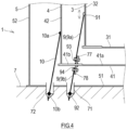
- FIG. 4 is a diagram for explaining Third Example of the structure in which the inner tank side plate 32 and the tank foundation 7 are coupled to each other by the first anchor straps 9.
- the intermediate tank bottom plate 41 includes a first coupling portion 77 located at the inner wall-side portion and a second coupling portion 78 located at the outer wall-side portion. It is desirable that the first coupling portion 77 and the second coupling portion 78 be located at the annular plate 41b of the intermediate tank bottom plate 41.
- Each of the first coupling portion 77 and the second coupling portion 78 includes an elongated hole that is substantially parallel to an extending direction of the first anchor strap 9.
- the first anchor strap 9 of Third Example is divided at a position between the first intermediate portion 93 and the second intermediate portion 94 and includes: the first strap body 9a extending from the first end portion 91 coupled to the inner tank side plate 32 to the first intermediate portion 93 coupled to the first coupling portion 77; and the second strap body 9b extending from the second intermediate portion 94 coupled to the second coupling portion 78 to the second end portion 92 coupled to the tank foundation 7.
- the first strap body 9a and the second strap body 9b are located on a substantially straight line.
- the first intermediate portion 93 of the first anchor strap 9 and the first coupling portion 77 are pin-joined to each other so as to be turnable.
- first intermediate portion 93 of the first strap body 9a and the first coupling portion 77 are pin-joined to each other by a pin inserted into the first intermediate portion 93 of the first strap body 9a and the elongated hole of the first coupling portion 77.
- a coupling position of the first intermediate portion 93 is variable within a range of the elongated hole located at the first coupling portion 77.
- the second intermediate portion 94 of the first anchor strap 9 and the second coupling portion 76 are pin-joined to each other so as to be turnable.
- the second intermediate portion 94 of the second strap body 9b and the second coupling portion 78 are pin-joined to each other by a bolt inserted into the second intermediate portion 94 of the second strap body 9b and the elongated hole of the second coupling portion 78.
- a coupling position of the second intermediate portion 94 is variable within a range of the elongated hole located at the second coupling portion 78.
- both of the first intermediate portion 93 and the second intermediate portion 94 do not have to be pin-joined, and one of the first intermediate portion 93 and the second intermediate portion 94 may be pin-joined.
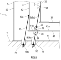
- FIG. 5 is a diagram for explaining a modified example of Third Example of the structure in which the inner tank side plate 32 and the tank foundation 7 are coupled to each other by the first anchor straps 9.
- the first coupling portion 77 and the second coupling portion 78 are located at the annular plate 41b of the intermediate tank bottom plate 41.
- the first intermediate portion 93 of the first anchor strap 9 and the first coupling portion 77 are pin-joined to each other by a bolt inserted into an elongated hole of the first coupling portion 77.
- a coupling position of the first intermediate portion 93 is variable within the range of the elongated hole of the first coupling portion 77.
- the second intermediate portion 94 of the first anchor strap 9 and the second coupling portion 78 are pin-joined to each other by a bolt inserted into an elongated hole of the second coupling portion 78.
- a coupling position of the second intermediate portion 94 is variable within the range of the elongated hole of the second coupling portion 78.
- the first anchor strap 9 does not penetrate the intermediate tank 4. Therefore, the airtightness of the intermediate tank 4 does not deteriorate, and the leakage of the gas from the first inter-tank region 61 to the second inter-tank region 62 can be prevented more surely.
- each of the first intermediate portion 93 and the second intermediate portion 94 is displaceable within the range of the elongated hole. Therefore, stress acting on the first anchor strap 9 by thermal contraction of the inner tank 3 can be relaxed by the displacement of the first intermediate portion 93 and the second intermediate portion 94.
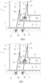
- FIG. 6 is a diagram for explaining Fourth Example of the structure in which the inner tank side plate 32 and the tank foundation 7 are coupled to each other by the first anchor straps 9.
- a connection box 80 including a side plate 81 and an upper plate 82 is located at the intermediate tank bottom plate 41.
- the side plate 81 is a tubular body fixed to the annular plate 41b of the intermediate tank bottom plate 41 by welding.
- An upper portion of the side plate 81 is closed by the upper plate 82.
- the upper plate 82 includes an expandable portion. The expandable portion is realized by, for example, corrugation formed on the upper plate 82.
- the first anchor strap 9 according to Fourth Example is a band-shaped or wire-shaped body that is continuous from the first end portion 91 to the second end portion 92.
- the first anchor strap 9 according to Fourth Example is inserted into the upper plate 82 at a position between the first end portion 91 and the second end portion 92.
- a portion located right above a portion inserted into the upper plate 82 is the first intermediate portion 93, and a portion right under the portion inserted into the upper plate 82 is the second intermediate portion 94.
- an upper surface of the upper plate 82 and the first intermediate portion 93 of the first anchor strap 9 are coupled to each other by welding, and a lower surface of the upper plate 82 and the second intermediate portion 94 of the first anchor strap 9 are coupled to each other by welding.
- a gap between the upper plate 82 and the first intermediate portion 93 and a gap between the upper plate 82 and the second intermediate portion 94 are filled by welding, and therefore, the airtightness of the intermediate tank 4 is maintained.
- connection box 80 includes the expandable portion. Therefore, unlike First Example, the stress acting on the intermediate tank 4 by the thermal contraction of the inner tank 3 can be relaxed by the deformation of the expandable portion.
- FIG. 7 is a diagram for explaining Fifth Example of the structure in which the inner tank side plate 32 and the tank foundation 7 are coupled to each other by the first anchor straps 9.
- the connection box 80 including the side plate 81 and the upper plate 82 is located at the intermediate tank bottom plate 41.
- the side plate 81 is a tubular body fixed to the annular plate 41b of the intermediate tank bottom plate 41 by welding.
- the upper portion of the side plate 81 is closed by the upper plate 82.
- the upper plate 82 includes an expandable portion. The expandable portion is realized in such a manner that the side plate 81 is formed by an expandable pipe.
- the first anchor strap 9 according to Fifth Example is a band-shaped or wire-shaped body that is continuous from the first end portion 91 to the second end portion 92.
- the first anchor strap 9 according to Fifth Example is inserted into the upper plate 82 at a position between the first end portion 91 and the second end portion 92.
- a portion located right above a portion inserted into the upper plate 82 is the first intermediate portion 93, and a portion right under the portion inserted into the upper plate 82 is the second intermediate portion 94.
- the first anchor strap 9 may be divided at a position between the first intermediate portion 93 and the second intermediate portion 94 without being inserted into the upper plate 82.
- the upper surface of the upper plate 82 and the first intermediate portion 93 of the first anchor strap 9 are coupled to each other by welding, and the lower surface of the upper plate 82 and the second intermediate portion 94 of the first anchor strap 9 are coupled to each other by welding.
- a gap between the upper plate 82 and the first intermediate portion 93 and a gap between the upper plate 82 and the second intermediate portion 94 are filled by welding, and therefore, the airtightness of the intermediate tank 4 is maintained.
- connection box 80 includes the expandable portion. Therefore, unlike First Example, the stress acting on the intermediate tank 4 by the thermal contraction of the inner tank 3 can be relaxed by the deformation of the expandable portion.
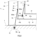
- FIG. 8 is a diagram for explaining Sixth Example of the structure in which the inner tank side plate 32 and the tank foundation 7 are coupled to each other by the first anchor straps 9.
- the intermediate tank bottom plate 41 includes: the annular plate 41b forming a peripheral portion of the intermediate tank bottom plate 41; and a bracket 84 fixed to the annular plate 41b and the intermediate tank side plate 42 by welding at the inner wall-side portion of the intermediate tank 4.
- the first anchor strap 9 of Sixth Example is divided at a position between the first intermediate portion 93 and the second intermediate portion 94 and includes: the first strap body 9a extending from the first end portion 91 coupled to the outer wall of the inner tank side plate 32 to the first intermediate portion 93 coupled to the bracket 84; and the second strap body 9b extending from the second intermediate portion 94 coupled to the outer wall of the intermediate tank side plate 42 to the second end portion 92 coupled to the tank foundation 7.
- the first strap body 9a and the second strap body 9b are coupled to each other by a rigid body including the annular plate 41b of the intermediate tank bottom plate 41, a lower portion of the intermediate tank side plate 42, and the bracket 84.
- the second strap body 9b and the second anchor strap 10 are integrated with each other. Therefore, as the second anchor strap 10 of Sixth Example, it is desirable to use a band-shaped body that is wider or thicker than those of First to Fifth Examples. However, the second strap body 9b and the second anchor strap 10 may be separately located and may be lined up.
- the first anchor strap 9 does not penetrate the intermediate tank 4. Therefore, the airtightness of the intermediate tank 4 does not deteriorate, and the leakage of the gas from the first inter-tank region 61 to the second inter-tank region 62 can be prevented more surely.
- the triple containment tank 1 includes:
- the first anchor strap 9 includes the first end portion 91 coupled to the inner tank side plate 32 and the second end portion 92 coupled to the tank foundation 7.
- the first anchor strap 9 further includes: the first intermediate portion 93 located between the first end portion 91 and the second end portion 92 and coupled to the inner wall-side portion of the intermediate tank 4 which is exposed to the first inter-tank region 61; and the second intermediate portion 94 located between the first end portion 91 and the second end portion 92 and coupled to the outer wall-side portion of the intermediate tank 4 which is exposed to the second inter-tank region 62.
- the inner tank side plate 32 and the tank foundation 7 can be coupled to each other by the first anchor strap 9 with the intermediate tank 4 interposed therebetween.
- the first inter-tank region 61 and the inside of the inner tank 3 communicate with each other.
- the first inter-tank region 61 is filled with the vaporized gas of the liquefied gas.
- the second inter-tank region 62 is filled with the gas having a higher boiling point than the liquefied gas.
- the first intermediate portion 93 of the first anchor strap 9 is coupled to the inner wall-side portion of the intermediate tank 4, and the second intermediate portion 94 of the first anchor strap 9 is coupled to the outer wall-side portion of the intermediate tank 4. Therefore, the first anchor strap 9 can be included while maintaining the airtightness inside and outside the intermediate tank 4. Thus, even when the gas filled in the first inter-tank region 61 and the gas filled in the second inter-tank region 62 are different from each other as described above, the leakage of these gases and the mixture of these gases are prevented.
- the pressure difference between the inner and outer tanks can be reduced, and the stress acting on the first anchor strap 9 can be reduced.
- the first anchor strap 9 may be a band-shaped or wire-shaped body that is continuous from the first end portion 91 to the second end portion 92.
- the first anchor strap 9 may be inserted into the intermediate tank bottom plate 41 at a position between the first end portion 91 and the second end portion 92.
- the first intermediate portion 93 and the second intermediate portion 94 may be coupled to the intermediate tank bottom plate 41 by welding.
- the intermediate tank bottom plate 41 may include: the first coupling portion 75 or 77 located at the inner wall-side portion; and the second coupling portion 76 or 78 located at the outer wall-side portion.
- the first anchor strap 9 may include: the first strap body 9a extending from the first end portion 91 coupled to the inner tank side plate 32 to the first intermediate portion 93 coupled to the first coupling portion 75 or 77; and the second strap body 9b extending from the second intermediate portion 94 coupled to the second coupling portion 76 or 78 to the second end portion 92 coupled to the tank foundation 7.
- the first strap body 9a and the second strap body 9b may be located on a substantially straight line.
- At least one of the first intermediate portion 93 and the second intermediate portion 94 may be pin-joined.
- the intermediate tank bottom plate 41 may include the connection box 80 including the side plate 81 and the upper plate 82.
- the first intermediate portion 93 and the second intermediate portion 94 may be coupled to the upper plate 82 by welding.
- the first anchor strap 9 may be a band-shaped or wire-shaped body that is continuous from the first end portion 91 to the second end portion 92.
- the intermediate tank bottom plate 41 may include: the annular plate 41b located at the peripheral portion of the intermediate tank bottom plate 41; and the bracket 84 fixed to the annular plate 41b and the intermediate tank side plate 42 at the inner wall-side portion of the intermediate tank 4.
- the first anchor strap 9 may include: the first strap body 9a extending from the first end portion 91 coupled to the inner tank side plate 32 to the first intermediate portion 93 coupled to the bracket 84; and the second strap body 9b extending from the second intermediate portion 94 coupled to the outer wall-side portion of the intermediate tank side plate 42 to the second end portion 92 coupled to the tank foundation 7.
- the second anchor strap 10 may be integrated with the second strap body 9b or may be lined up with the second strap body 9b.
- the inner tank 3, the intermediate tank 4, and the outer tank 5 are cylindrical flat-bottomed tanks.
- the shape of the tank is not limited to a cylindrical shape, and the tank may be a flat-bottomed tank having a substantially polygonal tubular shape.
- the dike 6 is located around the triple containment tank 1.
- the dike 6 may be omitted.
Landscapes
- Engineering & Computer Science (AREA)
- Mechanical Engineering (AREA)
- General Engineering & Computer Science (AREA)
- Physics & Mathematics (AREA)
- Thermal Sciences (AREA)
- Filling Or Discharging Of Gas Storage Vessels (AREA)
- Apparatus Associated With Microorganisms And Enzymes (AREA)
Applications Claiming Priority (2)
| Application Number | Priority Date | Filing Date | Title |
|---|---|---|---|
| JP2020218833A JP7498659B2 (ja) | 2020-12-28 | 2020-12-28 | 三重殻タンク |
| PCT/JP2021/047383 WO2022145296A1 (ja) | 2020-12-28 | 2021-12-21 | 三重殻タンク |
Publications (4)
| Publication Number | Publication Date |
|---|---|
| EP4269864A1 true EP4269864A1 (de) | 2023-11-01 |
| EP4269864A4 EP4269864A4 (de) | 2024-10-30 |
| EP4269864B1 EP4269864B1 (de) | 2026-04-08 |
| EP4269864B8 EP4269864B8 (de) | 2026-05-13 |
Family
ID=82260698
Family Applications (1)
| Application Number | Title | Priority Date | Filing Date |
|---|---|---|---|
| EP21915156.0A Active EP4269864B8 (de) | 2020-12-28 | 2021-12-21 | Dreiwandiger tank |
Country Status (7)
| Country | Link |
|---|---|
| US (1) | US12338955B2 (de) |
| EP (1) | EP4269864B8 (de) |
| JP (1) | JP7498659B2 (de) |
| KR (1) | KR102844593B1 (de) |
| AU (1) | AU2021414736B2 (de) |
| TW (1) | TWI844807B (de) |
| WO (1) | WO2022145296A1 (de) |
Families Citing this family (6)
| Publication number | Priority date | Publication date | Assignee | Title |
|---|---|---|---|---|
| JP7755943B2 (ja) * | 2021-06-04 | 2025-10-17 | 川崎重工業株式会社 | 多重殻タンク |
| CN117346054A (zh) * | 2022-06-28 | 2024-01-05 | 气体运输技术公司 | 用于储罐的支撑结构 |
| JP2024112601A (ja) | 2023-02-08 | 2024-08-21 | 川崎重工業株式会社 | 液化水素貯蔵タンク |
| JP2024112602A (ja) * | 2023-02-08 | 2024-08-21 | 川崎重工業株式会社 | 液化水素貯蔵タンク及びその施工方法 |
| WO2024263702A1 (en) * | 2023-06-22 | 2024-12-26 | Cb&I Sts Delaware Llc | Cryopumping-resistant lh2 storage vessel |
| AR133031A1 (es) * | 2023-06-22 | 2025-08-20 | Cb&I Sts Delaware Llc | Recipiente de almacenamiento de lh2 resistente al criobombeo |
Family Cites Families (15)
| Publication number | Priority date | Publication date | Assignee | Title |
|---|---|---|---|---|
| US2460355A (en) * | 1942-07-11 | 1949-02-01 | Linde Air Prod Co | Container for liquefied gases |
| US3768765A (en) * | 1972-02-14 | 1973-10-30 | Little Inc A | Thermally isolating structural support system and cryogenic assembly embodying the same |
| JPS5520937A (en) * | 1978-07-31 | 1980-02-14 | Ishikawajima Harima Heavy Ind Co Ltd | Inner tank supporting apparatus for multiple-shell tank |
| JPS5677474A (en) * | 1979-11-28 | 1981-06-25 | Ishikawajima Harima Heavy Ind | Method of constructing multiple shell tank |
| JPS58100727A (ja) | 1981-12-11 | 1983-06-15 | Hitachi Ltd | 容器の配管貫通部における漏洩検出装置 |
| JPS60245899A (ja) * | 1984-05-21 | 1985-12-05 | Hitachi Ltd | 極低温容器の断熱支持装置 |
| US4718239A (en) * | 1987-03-05 | 1988-01-12 | Union Carbide Corporation | Cryogenic storage vessel |
| JPS63158695U (de) * | 1987-04-06 | 1988-10-18 | ||
| JPH10220697A (ja) * | 1997-02-05 | 1998-08-21 | Ishikawajima Harima Heavy Ind Co Ltd | 低温タンクの内槽用アンカー構造 |
| JP4379899B2 (ja) | 1999-08-30 | 2009-12-09 | 株式会社Ihi | 低温タンク |
| JP2001248799A (ja) * | 2000-03-02 | 2001-09-14 | Ishikawajima Harima Heavy Ind Co Ltd | 低温タンクおよびその水張り試験方法 |
| JP2003269698A (ja) | 2002-03-12 | 2003-09-25 | Ishikawajima Harima Heavy Ind Co Ltd | 低温貯蔵タンクのアンカー |
| RU2554369C2 (ru) * | 2010-01-28 | 2015-06-27 | Осака Гэс Ко., Лтд. | Криогенный резервуар |
| EP3877597A1 (de) * | 2018-11-09 | 2021-09-15 | Martin Power | Gebäude und verfahren zur konstruktion eines gebäudes |
| KR20200106684A (ko) | 2019-03-05 | 2020-09-15 | 쌍용건설 주식회사 | 길이조절형 와이어 연결장치 및 이를 이용한 중량체 인양방법 |
-
2020
- 2020-12-28 JP JP2020218833A patent/JP7498659B2/ja active Active
-
2021
- 2021-12-21 EP EP21915156.0A patent/EP4269864B8/de active Active
- 2021-12-21 WO PCT/JP2021/047383 patent/WO2022145296A1/ja not_active Ceased
- 2021-12-21 AU AU2021414736A patent/AU2021414736B2/en active Active
- 2021-12-21 KR KR1020237024742A patent/KR102844593B1/ko active Active
- 2021-12-21 US US18/269,645 patent/US12338955B2/en active Active
- 2021-12-24 TW TW110148653A patent/TWI844807B/zh active
Also Published As
| Publication number | Publication date |
|---|---|
| JP7498659B2 (ja) | 2024-06-12 |
| EP4269864B8 (de) | 2026-05-13 |
| TW202238032A (zh) | 2022-10-01 |
| KR20230118689A (ko) | 2023-08-11 |
| EP4269864A4 (de) | 2024-10-30 |
| WO2022145296A1 (ja) | 2022-07-07 |
| EP4269864B1 (de) | 2026-04-08 |
| AU2021414736B2 (en) | 2024-10-17 |
| US12338955B2 (en) | 2025-06-24 |
| CN116710697A (zh) | 2023-09-05 |
| JP2022103917A (ja) | 2022-07-08 |
| TWI844807B (zh) | 2024-06-11 |
| KR102844593B1 (ko) | 2025-08-11 |
| US20240060604A1 (en) | 2024-02-22 |
| AU2021414736A1 (en) | 2023-07-27 |
| AU2021414736A9 (en) | 2024-09-19 |
Similar Documents
| Publication | Publication Date | Title |
|---|---|---|
| EP4269864B1 (de) | Dreiwandiger tank | |
| KR102036421B1 (ko) | Lng 탱크, 및 lng 탱크와 상기 lng 탱크의 탱크 연결 공간 사이에서 적어도 하나의 파이프를 연결하기 위한 시스템 | |
| JP2025123561A (ja) | 多重殻タンク | |
| EP3760910B1 (de) | Doppelwandiger tank und flüssiggasträgerschiff | |
| EP4129814B1 (de) | Flüssiggasspeicherschiff | |
| US4461399A (en) | Liquid storage tank conduit connection | |
| JP7498848B2 (ja) | 三重殻タンク | |
| EP4174360A1 (de) | Doppelwandiger tank | |
| KR102742192B1 (ko) | 가압형 극저온 저장탱크의 패싱 홀 구조 | |
| KR20230138222A (ko) | 발사체용 분리형 2중 겹벽 단열탱크 | |
| US20250333238A1 (en) | Multiple-shell tank and heat insulation material supply method for multiple-shell tank | |
| KR102404669B1 (ko) | 액화가스 화물창 | |
| KR20170034548A (ko) | 화물창의 단열박스 및 그 제작 방법 | |
| TWI852202B (zh) | 真空絕熱低溫儲存容器 | |
| EP4538583A1 (de) | Speicherbehälter für tiefkaltes flüssiggas | |
| KR20260032798A (ko) | 리퀴드 돔 | |
| JP7261007B2 (ja) | 二重殻タンク | |
| US20240426425A1 (en) | Cryopumping-resistant lh2 storage vessel | |
| AU2024275714A1 (en) | Low-temperature storage tank |
Legal Events
| Date | Code | Title | Description |
|---|---|---|---|
| STAA | Information on the status of an ep patent application or granted ep patent |
Free format text: STATUS: THE INTERNATIONAL PUBLICATION HAS BEEN MADE |
|
| PUAI | Public reference made under article 153(3) epc to a published international application that has entered the european phase |
Free format text: ORIGINAL CODE: 0009012 |
|
| STAA | Information on the status of an ep patent application or granted ep patent |
Free format text: STATUS: REQUEST FOR EXAMINATION WAS MADE |
|
| 17P | Request for examination filed |
Effective date: 20230704 |
|
| AK | Designated contracting states |
Kind code of ref document: A1 Designated state(s): AL AT BE BG CH CY CZ DE DK EE ES FI FR GB GR HR HU IE IS IT LI LT LU LV MC MK MT NL NO PL PT RO RS SE SI SK SM TR |
|
| DAV | Request for validation of the european patent (deleted) | ||
| DAX | Request for extension of the european patent (deleted) | ||
| A4 | Supplementary search report drawn up and despatched |
Effective date: 20240927 |
|
| RIC1 | Information provided on ipc code assigned before grant |
Ipc: F17C 13/08 20060101AFI20240923BHEP |
|
| GRAP | Despatch of communication of intention to grant a patent |
Free format text: ORIGINAL CODE: EPIDOSNIGR1 |
|
| STAA | Information on the status of an ep patent application or granted ep patent |
Free format text: STATUS: GRANT OF PATENT IS INTENDED |
|
| INTG | Intention to grant announced |
Effective date: 20260108 |
|
| GRAS | Grant fee paid |
Free format text: ORIGINAL CODE: EPIDOSNIGR3 |
|
| GRAA | (expected) grant |
Free format text: ORIGINAL CODE: 0009210 |
|
| STAA | Information on the status of an ep patent application or granted ep patent |
Free format text: STATUS: THE PATENT HAS BEEN GRANTED |
|
| AK | Designated contracting states |
Kind code of ref document: B1 Designated state(s): AL AT BE BG CH CY CZ DE DK EE ES FI FR GB GR HR HU IE IS IT LI LT LU LV MC MK MT NL NO PL PT RO RS SE SI SK SM TR |
|
| REG | Reference to a national code |
Ref country code: CH Ref legal event code: F10 Free format text: ST27 STATUS EVENT CODE: U-0-0-F10-F00 (AS PROVIDED BY THE NATIONAL OFFICE) Effective date: 20260408 Ref country code: GB Ref legal event code: FG4D |
|
| REG | Reference to a national code |
Ref country code: CH Ref legal event code: Q17 Free format text: ST27 STATUS EVENT CODE: U-0-0-Q10-Q17 (AS PROVIDED BY THE NATIONAL OFFICE) Effective date: 20260416 |
|
| REG | Reference to a national code |
Ref country code: DE Ref legal event code: R096 Ref document number: 602021051894 Country of ref document: DE |
|
| REG | Reference to a national code |
Ref country code: IE Ref legal event code: FG4D |