EP4269893A1 - Kältemittelleckerkennung unter verwendung einer sensorlesekontextanalyse - Google Patents
Kältemittelleckerkennung unter verwendung einer sensorlesekontextanalyse Download PDFInfo
- Publication number
- EP4269893A1 EP4269893A1 EP23170074.1A EP23170074A EP4269893A1 EP 4269893 A1 EP4269893 A1 EP 4269893A1 EP 23170074 A EP23170074 A EP 23170074A EP 4269893 A1 EP4269893 A1 EP 4269893A1
- Authority
- EP
- European Patent Office
- Prior art keywords
- sensor
- outputs
- context
- refrigerant
- operable
- Prior art date
- Legal status (The legal status is an assumption and is not a legal conclusion. Google has not performed a legal analysis and makes no representation as to the accuracy of the status listed.)
- Pending
Links
Images


Classifications
-
- F—MECHANICAL ENGINEERING; LIGHTING; HEATING; WEAPONS; BLASTING
- F25—REFRIGERATION OR COOLING; COMBINED HEATING AND REFRIGERATION SYSTEMS; HEAT PUMP SYSTEMS; MANUFACTURE OR STORAGE OF ICE; LIQUEFACTION SOLIDIFICATION OF GASES
- F25B—REFRIGERATION MACHINES, PLANTS OR SYSTEMS; COMBINED HEATING AND REFRIGERATION SYSTEMS; HEAT PUMP SYSTEMS
- F25B49/00—Arrangement or mounting of control or safety devices
- F25B49/02—Arrangement or mounting of control or safety devices for compression type machines, plants or systems
-
- F—MECHANICAL ENGINEERING; LIGHTING; HEATING; WEAPONS; BLASTING
- F25—REFRIGERATION OR COOLING; COMBINED HEATING AND REFRIGERATION SYSTEMS; HEAT PUMP SYSTEMS; MANUFACTURE OR STORAGE OF ICE; LIQUEFACTION SOLIDIFICATION OF GASES
- F25B—REFRIGERATION MACHINES, PLANTS OR SYSTEMS; COMBINED HEATING AND REFRIGERATION SYSTEMS; HEAT PUMP SYSTEMS
- F25B49/00—Arrangement or mounting of control or safety devices
- F25B49/005—Arrangement or mounting of control or safety devices of safety devices
-
- F—MECHANICAL ENGINEERING; LIGHTING; HEATING; WEAPONS; BLASTING
- F24—HEATING; RANGES; VENTILATING
- F24F—AIR-CONDITIONING; AIR-HUMIDIFICATION; VENTILATION; USE OF AIR CURRENTS FOR SCREENING
- F24F11/00—Control or safety arrangements
- F24F11/30—Control or safety arrangements for purposes related to the operation of the system, e.g. for safety or monitoring
- F24F11/32—Responding to malfunctions or emergencies
- F24F11/36—Responding to malfunctions or emergencies to leakage of heat-exchange fluid
-
- F—MECHANICAL ENGINEERING; LIGHTING; HEATING; WEAPONS; BLASTING
- F28—HEAT EXCHANGE IN GENERAL
- F28F—DETAILS OF HEAT-EXCHANGE AND HEAT-TRANSFER APPARATUS, OF GENERAL APPLICATION
- F28F27/00—Control arrangements or safety devices specially adapted for heat-exchange or heat-transfer apparatus
-
- G—PHYSICS
- G06—COMPUTING OR CALCULATING; COUNTING
- G06F—ELECTRIC DIGITAL DATA PROCESSING
- G06F18/00—Pattern recognition
- G06F18/20—Analysing
- G06F18/21—Design or setup of recognition systems or techniques; Extraction of features in feature space; Blind source separation
- G06F18/214—Generating training patterns; Bootstrap methods, e.g. bagging or boosting
-
- G—PHYSICS
- G06—COMPUTING OR CALCULATING; COUNTING
- G06F—ELECTRIC DIGITAL DATA PROCESSING
- G06F18/00—Pattern recognition
- G06F18/20—Analysing
- G06F18/24—Classification techniques
-
- G—PHYSICS
- G06—COMPUTING OR CALCULATING; COUNTING
- G06N—COMPUTING ARRANGEMENTS BASED ON SPECIFIC COMPUTATIONAL MODELS
- G06N20/00—Machine learning
-
- F—MECHANICAL ENGINEERING; LIGHTING; HEATING; WEAPONS; BLASTING
- F25—REFRIGERATION OR COOLING; COMBINED HEATING AND REFRIGERATION SYSTEMS; HEAT PUMP SYSTEMS; MANUFACTURE OR STORAGE OF ICE; LIQUEFACTION SOLIDIFICATION OF GASES
- F25B—REFRIGERATION MACHINES, PLANTS OR SYSTEMS; COMBINED HEATING AND REFRIGERATION SYSTEMS; HEAT PUMP SYSTEMS
- F25B2500/00—Problems to be solved
- F25B2500/22—Preventing, detecting or repairing leaks of refrigeration fluids
- F25B2500/222—Detecting refrigerant leaks
-
- F—MECHANICAL ENGINEERING; LIGHTING; HEATING; WEAPONS; BLASTING
- F28—HEAT EXCHANGE IN GENERAL
- F28F—DETAILS OF HEAT-EXCHANGE AND HEAT-TRANSFER APPARATUS, OF GENERAL APPLICATION
- F28F2265/00—Safety or protection arrangements; Arrangements for preventing malfunction
- F28F2265/16—Safety or protection arrangements; Arrangements for preventing malfunction for preventing leakage
Definitions
- the present invention relates to a detection assembly operable to detect a refrigerant leak event and a method of operating a detection assembly to detect a refrigerant leak event.
- Exemplary embodiments relate to refrigerant detection assemblies for detecting leaks of moderate to low global warming potential (GWP) refrigerants, and more particularly, to refrigerant leak detection systems and methods operable to detect refrigerant leaks using a novel sensor-reading context analysis.
- GWP global warming potential
- a wide variety of technologies exist for cooling applications including but not limited to evaporative cooling, convective cooling, or solid state cooling such as electrothermic cooling.
- One of the most prevalent technologies in use for residential and commercial refrigeration and air conditioning is the vapor compression refrigerant heat transfer loop.
- existing refrigerants are effective coolants, the effect they can have on the environment has led to the institution of requirements that new refrigerants, which have moderate-to-low GWP values, be employed instead.
- Moderate-to-low GWP refrigerants e.g., A2L refrigerants
- HVAC&R heating, ventilation, air conditioning and refrigeration
- Refrigerant leaks can be detected using various types of refrigerant detection assemblies.
- Conventional refrigerant detection assemblies utilize threshold-based refrigerant leak detectors, such as a nondispersive infrared (NDIR) sensor or a metal-oxide-semiconductor-based (MOS-based) sensor, that compare sensor values with a single threshold to decide whether to trigger an alarm.
- threshold-based detection schemes have the drawback of false alarms (i.e., generating a leak alarm when no leak has actually occurred) at a rate that is higher than acceptable for most applications. Frequent false alarms lead to downtime and require visits from technicians, thereby compromising the trustworthiness of the overall refrigerant detection system and, more specifically, the trustworthiness of the refrigerant detection sensors used in the detection system.
- a detection assembly operable to detect a refrigerant leak event includes a sensor network and a controller.
- the sensor network is operable to generate sensor outputs including triggering-sensor (TS) outputs and triggering-sensor context (TSC) outputs.
- the controller is operable to perform a sensor-reading context analysis on the sensor outputs.
- the sensor-reading context analysis includes accessing a set of the sensor outputs that occurred within a context time window, and determining that a pattern of the set of sensor outputs represents the refrigerant leak event.
- the controller includes a classifier operable to execute a machine learning algorithm trained to perform the sensor-reading context analysis as a classification task.
- the machine learning algorithm has been trained using a training dataset including experimental data that results from experimental tests applied to the detection assembly, and in-use data that results from in-use operations of the detection assembly.
- accessing the set of the sensor outputs that occurred within the context time window is based at least in part on a determination that at least one of the TS outputs represents a triggering event.
- the triggering event includes the at least one of the TS outputs exceeding a threshold.
- the at least one of the TS outputs includes a parameter of a refrigerant flowing through a closed loop refrigeration circuit.
- the parameter includes a concentration.
- the sensor network includes a triggering sensor operable to generate the TS outputs, along with a first type of context sensor operable to generate a first type of the TSC outputs.
- the sensor network further includes a second type of context sensor operable to generate a second type of the TSC outputs.
- the first type of the TSC outputs include temperature data that represents ambient temperature of the triggering sensor; and the second type of the TSC outputs includes humidity data that represents ambient humidity of the triggering sensor.
- a method of operating a detection assembly to detect a refrigerant leak event includes using a sensor network to generate sensor outputs that include triggering-sensor (TS) outputs and triggering-sensor context (TSC) outputs, and using a controller to perform a sensor-reading context analysis on the sensor outputs.
- the sensor-reading context analysis includes accessing a set of the sensor outputs that occurred within a context time window, and determining that a pattern of the set of sensor outputs represents the refrigerant leak event.
- the controller includes a classifier operable to execute a machine learning algorithm trained to perform the sensor-reading context analysis as a classification task.
- the machine learning algorithm has been trained using a training dataset including experimental data that results from experimental tests applied to the detection assembly, and in-use data that results from in-use operations of the detection assembly.
- accessing the set of the sensor outputs that occurred within the context time window is based at least in part on a determination that at least one of the TS outputs represents a triggering event.
- the triggering event includes the at least one of the TS outputs exceeding a threshold.
- the at least one of the TS outputs includes a parameter of a refrigerant flowing through a closed loop refrigeration circuit.
- the parameter includes a concentration.
- the sensor network includes a triggering sensor operable to generate the TS outputs, and a first type of context sensor operable to generate a first type of the TSC outputs.
- the sensor network further includes a second type of context sensor operable to generate a second type of the TSC outputs.
- the first type of the TSC outputs include temperature data that represents ambient temperature of the triggering sensor; and the second type of the TSC outputs includes humidity data that represents ambient humidity of the triggering sensor.
- the invention also provides a method of operating a detection assembly according to the first aspect and optionally including any of the other features described above, to detect a refrigerant leak event, the method comprising using the sensor network to generate sensor outputs comprising triggering-sensor (TS) outputs and triggering-sensor context (TSC) outputs; and using the controller to perform the sensor-reading context analysis on the sensor outputs.
- TS triggering-sensor
- TSC triggering-sensor context
- Embodiments of the present disclosure provide methods and systems that improve the trustworthiness of refrigerant sensors in refrigerant leak detection assemblies.
- Embodiments of the refrigerant leak detection systems and methods described herein utilize a novel sensor-reading context analysis to detect refrigerant leaks.
- the novel sensor-reading context analysis uses a sensor network that includes refrigerant sensors operable to detect parameters of a refrigerant (i.e., "refrigerant parameters”), along with context sensors operable to detect parameters that can impact how the refrigerant sensor operates (i.e., "refrigerant-sensor context parameters").
- the refrigerant-sensor context parameters can cause the refrigerant sensor to output false alarm data that indicates a refrigerant leak when in fact no refrigerant leak has occurred.
- refrigerant-sensor context parameters can be incorporated into the leak detection determination, operating conditions that can impact how the refrigerant sensor operates are taken into account so that false alarm conditions can be reduced and, in most instances, averted.
- the sensor-reading context analysis utilizes a classifier having machine learning algorithms trained to determine whether features of the refrigerant parameters and the refrigerant-context parameters match the features of a refrigerant leak event.
- the machine learning algorithms extract features from how the refrigerant parameters and the refrigerant context parameters change over time.
- the classifier is trained using a training dataset developed from lab-based experimental tests and in-use tests applied to the refrigerant sensor.
- the refrigerant parameters can include refrigerant concentration; and the refrigerant-context parameters can include ambient humidity and/or ambient temperature of the refrigerant sensor.
- embodiments described herein improve the trustworthiness of refrigerant sensors by greatly reducing false alarm rates with no or little compromise in detection rate; reducing refrigerant system downtime; and reducing the need for service visits from technicians in response to leak detection system false alarms.
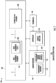
- FIG. 1 illustrates an example of a heating, ventilation, and air conditioning (HVAC) system 100 operable to incorporate a leak detection system 126.
- HVAC heating, ventilation, and air conditioning
- the leak detection system 126 is depicted separately from the cabinet 102. However, it is understood that some or all of the functionality of the leak detection system 126 can also be incorporated withing the cabinet 102.
- the HVAC system 100 is depicted in FIG. 1 as a furnace coil or fan coil unit 100. Although described herein as furnace or fan coil unit it should be appreciated that the HVAC system 100 can be any heating or cooling system. As shown, the furnace coil or fan coil unit 100 includes a cabinet or housing duct 102 within which various components of the HVAC system are located. For example, housed within the cabinet 102 of the furnace coil or fan coil unit 100 is a heat exchanger assembly 104 operable to heat and/or cool the adjacent air. A blower or fan assembly 106 can also be arranged within the cabinet 102 or alternatively, at a position outside of but in fluid communication with the cabinet 102.
- the blower 106 is operable to circulate a flow of air A through the interior of the cabinet 102, across the heat exchanger assembly 104.
- the blower 106 can be positioned either downstream with respect to the heat exchanger assembly 104 (i.e., a "draw through” configuration), or upstream with respect to the heat exchanger assembly 104 (i.e., a "blow through” configuration), as shown in FIG. 1 .
- the heat exchanger assembly 104 is part of a closed loop refrigeration circuit through which refrigeration (not shown separately from the heat exchanger assembly 104) flows.
- the heat exchanger assembly 104 can include any of a plurality of configurations. As illustrated in FIG. 1 , the heat exchanger assembly 104 includes one or more heat exchanger coils 108, which can be arranged in a non-linear configuration.
- the heat exchanger assembly 104 can have a generally V-shaped configuration, a generally A-shaped configuration, or a generally N-shaped configuration, or any other suitable configuration as is known in the art.
- the heat exchanger assembly 104 can include a single heat exchanger coil 108 arranged at an angle with respect to the flow path of air A through the cabinet 102.
- the heat exchanger assembly 104 absorbs heat from the air A passing through the heat exchanger assembly 104 and the resultant cool air A is provided to a space to be conditioned. It should be understood that the refrigeration system illustrated herein is intended as an example only and that a HVAC system 100 having any suitable configuration is within the scope of the disclosure.
- the HVAC system 100 can include the leak detection system 126 operable to detect a refrigerant leak of the cabinet 102.
- the leak detection system 126 includes a sensor network 110 and a controller 120, configured and arranged as shown.
- the controller 120 includes a sensor-reading context analyzer 122; and the sensor network 110 includes refrigerant sensor(s) (or triggering sensor) 112 and refrigerant-sensor context sensor(s) (or triggering-sensor context sensor(s)) 114.
- the refrigerant sensor(s) 112 can be coupled to the cabinet 102 in a way that allows the refrigerant sensor 112 to measure parameters of the refrigerant (not shown separately) that can provide an indication of a refrigerant leak.
- the refrigerant parameter can be a concentration of the refrigerant in the heat exchanger assembly 104 because the concentration of the refrigerant in the heat exchanger assembly 104 can provide an indication of whether or not refrigerant is leaking from the system 100 (i.e., refrigerant concentration in the system 100 increases where fluid is leaking from the system 100).
- the refrigerant sensor(s) 112 include but are not limited to a point sensor and a line of sight or beam sensor.
- the technologies used by one or more of the refrigerant sensors 112 can include non-dispersive infrared (NDIR), photoacoustic spectroscopy (PAS), quantum cascade laser spectroscopy (QCLS), tunable diode laser spectroscopy (TDLS), thermal conductivity (TC), metal oxide semiconductor (MOS), ultrasonic, speed of sound, and ultraviolet spectroscopy for example.
- NDIR non-dispersive infrared
- PAS photoacoustic spectroscopy
- QCLS quantum cascade laser spectroscopy
- TDLS tunable diode laser spectroscopy
- TC thermal conductivity
- MOS metal oxide semiconductor
- ultrasonic speed of sound
- ultraviolet spectroscopy for example.
- any suitable type of refrigerant sensor 112 may be used.
- the refrigerant-sensor context sensor(s) 114 can be any suitable sensor or sensor assembly that measures parameters of the context or conditions in which the refrigerant sensor(s) 112 operate.
- refrigerant sensor(s) 112 can be positioned near the heat exchanger assembly 104 so that the refrigerant sensor(s) 112 will be exposed to the high/low humidity and temperature cycles that result from the heat exchanger assembly 104 cycling through blowing cold air, warm air, cold air, warm air, etc.
- the refrigerant-sensor context sensor(s) 114 can include any suitable sensor for measuring ambient humidity to which the refrigerant sensor(s) are exposed.
- the refrigerant-sensor context sensor(s) 114 can include any suitable sensor for measuring ambient temperature to which the refrigerant sensor(s) are exposed.
- the controller 120 can include the sensor-reading context analyzer module 122, which is operable to analyze the outputs from the sensor network 110 to determine whether or not refrigerant is leaking from the system 100. Because the outputs from the sensor network 110 include outputs from the refrigerant-sensor context sensor(s) 114, operating conditions that can impact how the refrigerant sensor(s) 112 operate are taken into account by the sensor-reading context analyzer 122 so that false alarm conditions can be reduced and, in most instances, averted.
- the sensor-reading context analyzer module 122 is operable to analyze the outputs from the sensor network 110 to determine whether or not refrigerant is leaking from the system 100. Because the outputs from the sensor network 110 include outputs from the refrigerant-sensor context sensor(s) 114, operating conditions that can impact how the refrigerant sensor(s) 112 operate are taken into account by the sensor-reading context analyzer 122 so that false alarm conditions can be reduced and, in most instances, averted.
- the sensor-reading context analyzer 122 can utilize a classifier having machine learning algorithms (e.g., classifier 410 and machine learning algorithms 412 shown in FIG. 4 ) trained to determine whether features of the outputs from the sensor network 110 match the features of a refrigerant leak event.
- the machine learning algorithms can extract features from how the outputs from the sensor network 110 change over time.
- the classifier can be trained using a training dataset developed from lab-based experimental tests and in-use tests applied to the refrigerant sensor(s) 112.
- outputs from the refrigerant sensor(s) 112 can include refrigerant concentration; and the outputs from the refrigerant-sensor context sensor(s) 114 can include ambient humidity and/or ambient temperature to which the refrigerant sensor(s) 112 are or have been exposed. Accordingly, embodiments described herein improve the trustworthiness of the refrigerant sensor(s) 112 by greatly reducing false alarm rates with no or little compromise in detection rate; reducing refrigerant system downtime; and reducing the need for service visits from technicians in response to leak detection system false alarms.
- the controller 120 can be operably coupled to the sensor network 110 and to a motor (not shown separately) of the blower 106.
- a thermostat 130 for selecting a temperature demand of the area to be conditioned by the HVAC system 100 is arranged in communication with the controller 120.
- the controller 120 is operable to control operation of the furnace coil or fan coil unit 100 in response to the temperature setting of the thermostat 130.
- the leak detection system 126 enters an alarm state and the controller 120 is operable to operate the HVAC system 100 in a first mode.
- the controller 120 can be made operable to isolate one or more possible ignition sources by turning off the HVAC system 100 as needed.
- the controller 120 could cut power to the thermostat 130 to prevent calls for heat and/or cooling provided to the thermostat 130 from being communicated to the controller 120 and activating the HVAC system 100.
- isolating one or more possible ignition sources includes de-energizing HVAC operating circuits directly, such as the furnace ignition circuit, AC compressor circuit, etc.
- the controller 120 can be made operable to initiate operation of a blower 106. Operation of the blower 106 is intended to dissipate the refrigerant within the atmosphere.
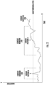
- FIG. 2 is a simplified plot diagram
- FIG. 3 is a flow diagram illustrating a methodology 300. More specifically, FIG. 2 is a plot diagram illustrating a simplified example of sensor output(s) 220 of the sensor network 110, content windows 230, 240, sensor patterns A, B, and a leak threshold (Th), that can be utilized by the sensor-reading context analyzer 122 (shown in FIG. 1 ) to perform the methodology 300 shown in FIG. 3 .
- Th leak threshold
- the methodology 300 begins at block 302 by using the sensor network 110 (shown in FIG. 1 ) to make continuous sensor readings or measurements, and by using the controller 120 (shown in FIG. 1 ) to receive and store the sensor readings or measurements.
- FIG. 2 provides a simplified representation of the sensor readings of the sensor network 110 as sensor output(s) 220.
- the sensor output(s) 220 are simplified in that they represent a combination of sensor readings generated over time by the refrigerant sensor(s) 112 and the refrigerant-sensor context sensor(s) 114.
- each instance of the refrigerant sensor(s) 112 and the refrigerant-sensor context sensor(s) 114 generates its own sensor output.
- the sensor output(s) 220 are further simplified in that the change in magnitude over time in FIG. 2 is random and provided for ease of illustration and explanation.
- the pattern of the output(s) 220 is not intended to represent an actual or expected change in magnitude over time for the sensor readings generated by the sensor network 110.
- the output(s) 220 are intended to illustrate that the magnitude of the sensor readings from the sensor network 110 change over time, and are further intended to illustrate that the magnitude of the output(s) can exceed a leak threshold (Th) value.
- Th leak threshold
- the leak Th may correspond to a threshold for sensor readings from the sensor network 110, where the threshold functions as a trigger to capture the context window (e.g., context window 230 and/or context window 240 shown in FIG. 2 ) and the associated sensor output pattern (e.g., sensor output pattern A and/or context output pattern B shown in FIG. 2 ) that will be analyzed by the sensor-readings context analyzer 122 (shown in FIG. 1 ).
- the threshold functions as a trigger to capture the context window (e.g., context window 230 and/or context window 240 shown in FIG. 2 ) and the associated sensor output pattern (e.g., sensor output pattern A and/or context output pattern B shown in FIG. 2 ) that will be analyzed by the sensor-readings context analyzer 122 (shown in FIG. 1 ).
- Sensor readings from the refrigerant sensor(s) 112 may function as the trigger, and the leak Th may be a value of a sensor reading from the refrigerant sensor(s) 112 that provides a preliminary indication that the refrigerant sensor(s) 112 may or may not have detected a refrigerant leak in the system 100 (shown in FIG. 1 ).
- the sensor-reading context analyzer 122 may perform additional analysis using the information depicted in FIG. 2 to determine whether the preliminary indication that the refrigerant sensor(s) 112 may or may not have detected a refrigerant leak represents an actual refrigerant leak or a false alarm.
- the methodology 300 moves to decision block 304 where the controller 120 (shown in FIG. 1 ) monitors the sensor outputs stored at block 302 to determine when the portion of the sensor output(s) 220 generated by the refrigerant sensor(s) 112 exceeds the leak Th (shown in FIG. 2 ). If the answer to the inquiry at decision block 304 is no, the methodology 300 returns to the input of decision block 304 and continues to monitor the sensor outputs stored at block 302.
- the methodology 300 moves to block 306 where the controller 120 determines, selects, and/or accesses a context window (e.g., context window 230 and/or context window 240 shown in FIG. 2 ) around the point in time where the portion of the sensor output(s) 220 generated by the refrigerant sensor(s) 112 exceeds the leak Th.
- a context window e.g., context window 230 and/or context window 240 shown in FIG. 2
- the width or duration of the context window needs to be large enough such that the sensor pattern (e.g., sensor output pattern A and/or sensor output pattern B shown in FIG. 2 ) defined by the context window provides sufficient data for the sensor pattern analysis at decision block 312.
- the width or size of the context window may be selected in advance of initiating the methodology 300.
- the width or size of the context window may be determined dynamically by the sensor-reading context analyzer 122 using the sensor output(s) 220.
- the sensor-reading context analyzer 122 includes a classifier (e.g., classifier 410 shown in FIG. 4 )
- the classifier can be trained to dynamically selected the context window based on a dynamic determination of the width or duration of the sensor output pattern (e.g., sensor output pattern A and/or sensor output pattern B) needed in order to determine at a sufficiently high confident level whether sensor readings from the refrigerant sensor(s) 112 exceeding leak Th represent an actual refrigerant leak or a false alarm.
- the controller 120 determines whether or not the selected or determined context window has ended. If the answer to the inquiry at decision block 308 is no, the methodology 300 returns to the input the decision block 308. If the answer to the inquiry at decision block 308 is yes, the context window has closed or ended, and the methodology 300 moves to block 310 where the controller 120 captures the sensor output pattern (e.g., sensor output pattern A and/or sensor output pattern B shown in FIG. 2 ) of the selected context window (e.g., context window 230 and/or context window 240 shown in FIG. 2 ).
- the sensor output pattern e.g., sensor output pattern A and/or sensor output pattern B shown in FIG. 2
- the selected context window e.g., context window 230 and/or context window 240 shown in FIG. 2 .
- the methodology 300 moves to decision block 312, where the controller 120 and the sensor-reading context analyzer 122 evaluate the sensor pattern captured at block 310 to determine whether the refrigerant sensor output exceeding leak Th at decision block 304 represents an actual refrigerant leak or a false alarm.
- the analysis performed by the sensor-reading context analyzer 122 at decision block 304 may utilize a classifier (e.g., classifier 410 shown in FIG. 4 ) having machine learning algorithms (e.g., machine learning algorithms 412 shown in FIG. 4 ) trained to determine whether features of the sensor pattern match the features of a refrigerant leak event.
- the machine learning algorithms may extract features from the sensor pattern changes over time.
- the classifier may be trained using a training dataset developed from lab-based experimental tests and in-use tests applied to the refrigerant sensor(s) 112.
- the methodology 300 moves to block 320 and logs the various aspects of the evaluations at decision block 304 and decision block 312 as a false alarm. From block 320, the methodology 300 branches to block 318 and to another iteration of decision block 304 and the overall methodology 300. Where the evaluation at decision block 312 is performed by a trained classifier (e.g., the classifier 410 shown in FIG. 4 ), block 318 uses the false alarm event logged at block 320 to update the trained classifier of decision block 312. If the answer to the inquiry at decision block 312 is yes, the methodology 300 moves to block 314 where the controller 120 initiates an alarm and logs the alarm as an alarm event.
- a trained classifier e.g., the classifier 410 shown in FIG. 4
- the methodology 300 branches to block 318 and block 316. Where the evaluation at decision block 312 is performed by a trained classifier, block 318 uses the alarm event logged at block 314 to update the trained classifier of decision block 312. At block 316, the methodology 300 initiates a refrigerant leak response strategy, which can include shutting down the HVAC system 100 (shown in FIG. 1 ) or initiating a service call.
- a refrigerant leak response strategy can include shutting down the HVAC system 100 (shown in FIG. 1 ) or initiating a service call.
- machine learning techniques can be implemented using machine learning and/or natural language processing techniques.
- machine learning techniques are run on so-called "learning machines,” which can be implemented as programmable computers operable to run sets of machine learning algorithms and/or natural language processing algorithms.
- Machine learning algorithms incorporate knowledge from a variety of disciplines, including neurophysiology, cognitive science/psychology, physics (statistical mechanics), control theory, computer science, artificial intelligence, statistics/mathematics, pattern recognition, computer vision, parallel processing and hardware (e.g., digital/analog/VLSI/optical).
- Unstructured real-world data in its native form e.g., images, sound, text, or time series data
- a numerical form e.g., a vector having magnitude and direction
- the machine learning algorithm performs multiple iterations of learning-based analysis on the real-world data vectors until patterns (or relationships) contained in the real-world data vectors are uncovered and learned.
- the learned patterns/relationships function as predictive models that can be used to perform a variety of tasks, including, for example, classification (or labeling) of real-world data and clustering of real-world data.
- Classification tasks often depend on the use of labeled datasets to train the classifier (i.e., the model) to recognize the correlation between labels and data. This is known as supervised learning. Examples of classification tasks include identifying objects in images (e.g., stop signs, pedestrians, lane markers, etc.), recognizing gestures in video, detecting voices, detecting voices in audio, identifying particular speakers, transcribing speech into text, and the like. Clustering tasks identify similarities between objects, which the clustering task groups according to those characteristics in common and which differentiate them from other groups of objects. These groups are known as "clusters.”
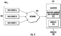
- FIG. 4 depicts a block diagram showing a classifier system 400 capable of implementing various predicting and determining aspects of the embodiments described herein. More specifically, the functionality of the system 400 can be used in embodiments to generate various models and/or sub-models that can be used to implement predicting and determining functionality in embodiments of the invention.
- the classifier system 400 includes multiple data sources 402 in communication (e.g., through a network 404) with a classifier 410. In some examples, the data sources 402 can bypass the network 404 and feed directly into the classifier 410.
- the data sources 402 provide data/information inputs that will be evaluated by the classifier 410 in accordance with embodiments.
- the data sources 402 also provide data/information inputs that can be used by the classifier 410 to train and/or update model(s) 416 created by the classifier 410.
- the data sources 402 can be implemented as a wide variety of data sources, including but not limited to, sensors operable to gather real time data, data repositories (including training data repositories), and outputs from other classifiers.
- the network 404 can be any type of communications network, including but not limited to local networks, wide area networks, private networks, the Internet, and the like.
- the classifier 410 can be implemented as algorithms executed by a programmable computer such as the computing system 600 (shown in FIG. 6 ). As shown in FIG. 4 , the classifier 410 includes a suite of machine learning (ML) algorithms 412; and model(s) 416 that are relationship (or prediction) algorithms generated (or learned) by the ML algorithms 412.
- ML machine learning
- model(s) 416 that are relationship (or prediction) algorithms generated (or learned) by the ML algorithms 412.
- the algorithms 412, 416 of the classifier 410 are depicted separately for ease of illustration and explanation. The functions performed by the various algorithms 412, 416 of the classifier 410 can be distributed differently than shown. Natural language processing (NLP) algorithms can be integrated within the ML algorithms 412.
- NLP Natural language processing
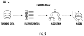
- FIG. 5 depicts an example of a learning phase 500 performed by the ML algorithms 412 to generate the above-described models 416.
- the classifier 410 extracts features from the training data and converts the features to vector representations that can be recognized and analyzed by the ML algorithms 412.
- the features vectors are analyzed by the ML algorithm 412 to "classify" the training data against the target model (or the model's task) and uncover relationships between and among the classified training data.
- suitable implementations of the ML algorithms 412 include but are not limited to neural networks, support vector machines (SVMs), logistic regression, decision trees, hidden Markov Models (HMMs), etc.
- the learning or training performed by the ML algorithms 412 can be supervised, unsupervised, or a hybrid that includes aspects of supervised and unsupervised learning.
- Supervised learning is when training data is already available and classified/labeled.
- Unsupervised learning is when training data is not classified/labeled so must be developed through iterations of the classifier 410 and the ML algorithms 412.
- Unsupervised learning can utilize additional learning/training methods including, for example, clustering, anomaly detection, neural networks, deep learning, and the like.
- the data sources 402 that generate "real world” data are accessed, and the "real world” data is applied to the models 416 to generate usable versions of the results 420.
- the results 420 can be fed back to the classifier 410 and used by the ML algorithms 412 as additional training data for updating and/or refining the models 416.
- FIG. 6 illustrates an example of a computer system 600 that can be used to implement the controller 120 described herein.
- the computer system 600 includes an exemplary computing device ("computer") 602 configured for performing various aspects of the content-based semantic monitoring operations described herein.
- exemplary computer system 600 includes network 614, which connects computer 602 to additional systems (not depicted) and can include one or more wide area networks (WANs) and/or local area networks (LANs) such as the Internet, intranet(s), and/or wireless communication network(s).
- WANs wide area networks
- LANs local area networks
- Computer 602 and additional system are in communication via network 614, e.g., to communicate data between them.
- Exemplary computer 602 includes processor cores 604, main memory (“memory”) 610, and input/output component(s) 612, which are in communication via bus 603.
- Processor cores 604 includes cache memory (“cache") 606 and controls 608, which include branch prediction structures and associated search, hit, detect and update logic, which will be described in more detail below.
- Cache 606 can include multiple cache levels (not depicted) that are on or off-chip from processor 604.
- Memory 610 can include various data stored therein, e.g., instructions, software, routines, etc., which, e.g., can be transferred to/from cache 606 by controls 608 for execution by processor 604.
- Input/output component(s) 612 can include one or more components that facilitate local and/or remote input/output operations to/from computer 602, such as a display, keyboard, modem, network adapter, etc. (not depicted).
- Examples described herein can be a system, a method, and/or a computer program product at any possible technical detail level of integration
- the computer program product can include a computer readable storage medium (or media) having computer readable program instructions thereon for causing a controller or processor to carry out aspects of the described examples.
- the computer readable storage medium can be a tangible device that can retain and store instructions for use by an instruction execution device.
- the computer readable storage medium can be, for example, but is not limited to, an electronic storage device, a magnetic storage device, an optical storage device, an electromagnetic storage device, a semiconductor storage device, or any suitable combination of the foregoing.
- a non-exhaustive list of more specific examples of the computer readable storage medium includes the following: a portable computer diskette, a hard disk, a random access memory (RAM), a read-only memory (ROM), an erasable programmable read-only memory (EPROM or Flash memory), a static random access memory (SRAM), a portable compact disc read-only memory (CD-ROM), a digital versatile disk (DVD), a memory stick, a floppy disk, a mechanically encoded device such as punch-cards or raised structures in a groove having instructions recorded thereon, and any suitable combination of the foregoing.
- RAM random access memory
- ROM read-only memory
- EPROM or Flash memory erasable programmable read-only memory
- SRAM static random access memory
- CD-ROM compact disc read-only memory
- DVD digital versatile disk
- memory stick a floppy disk
- a mechanically encoded device such as punch-cards or raised structures in a groove having instructions recorded thereon
- a computer readable storage medium is not to be construed as being transitory signals per se, such as radio waves or other freely propagating electromagnetic waves, electromagnetic waves propagating through a waveguide or other transmission media (e.g., light pulses passing through a fiber-optic cable), or electrical signals transmitted through a wire.
Landscapes
- Engineering & Computer Science (AREA)
- General Engineering & Computer Science (AREA)
- Physics & Mathematics (AREA)
- Mechanical Engineering (AREA)
- Theoretical Computer Science (AREA)
- Data Mining & Analysis (AREA)
- Thermal Sciences (AREA)
- General Physics & Mathematics (AREA)
- Evolutionary Computation (AREA)
- Artificial Intelligence (AREA)
- Computer Vision & Pattern Recognition (AREA)
- Combustion & Propulsion (AREA)
- Chemical & Material Sciences (AREA)
- Bioinformatics & Computational Biology (AREA)
- Evolutionary Biology (AREA)
- Life Sciences & Earth Sciences (AREA)
- Bioinformatics & Cheminformatics (AREA)
- Software Systems (AREA)
- Medical Informatics (AREA)
- Computing Systems (AREA)
- Mathematical Physics (AREA)
- Examining Or Testing Airtightness (AREA)
Applications Claiming Priority (1)
| Application Number | Priority Date | Filing Date | Title |
|---|---|---|---|
| US202263335014P | 2022-04-26 | 2022-04-26 |
Publications (1)
| Publication Number | Publication Date |
|---|---|
| EP4269893A1 true EP4269893A1 (de) | 2023-11-01 |
Family
ID=86226689
Family Applications (1)
| Application Number | Title | Priority Date | Filing Date |
|---|---|---|---|
| EP23170074.1A Pending EP4269893A1 (de) | 2022-04-26 | 2023-04-26 | Kältemittelleckerkennung unter verwendung einer sensorlesekontextanalyse |
Country Status (3)
| Country | Link |
|---|---|
| US (1) | US12385678B2 (de) |
| EP (1) | EP4269893A1 (de) |
| CN (1) | CN116951845A (de) |
Families Citing this family (1)
| Publication number | Priority date | Publication date | Assignee | Title |
|---|---|---|---|---|
| JP7805535B1 (ja) * | 2024-12-04 | 2026-01-23 | 三菱電機株式会社 | 冷媒漏洩検知装置及び冷凍サイクル装置 |
Citations (6)
| Publication number | Priority date | Publication date | Assignee | Title |
|---|---|---|---|---|
| US20130036796A1 (en) * | 2011-08-12 | 2013-02-14 | Mueller International, Llc | Enclosure for leak detector |
| US20140005958A1 (en) * | 2012-06-27 | 2014-01-02 | General Monitors, Inc. | Multi-spectral ultrasonic gas leak detector |
| US20160109162A1 (en) * | 2013-09-13 | 2016-04-21 | Mitsubishi Electric Corporation | Refrigeration cycle apparatus |
| US20190170603A1 (en) * | 2017-12-01 | 2019-06-06 | Johnson Controls Technology Company | Systems and methods for refrigerant leak management based on acoustic leak detection |
| EP3511657A1 (de) * | 2016-11-16 | 2019-07-17 | Mitsubishi Electric Corporation | Klimatisierungsvorrichtung und kältemittelleckagedetektionsverfahren |
| US20210356155A1 (en) * | 2018-11-29 | 2021-11-18 | Daikin Industries, Ltd. | Refrigerant leakage determination system and refrigeration cycle apparatus |
Family Cites Families (1)
| Publication number | Priority date | Publication date | Assignee | Title |
|---|---|---|---|---|
| US11125457B1 (en) * | 2020-07-16 | 2021-09-21 | Emerson Climate Technologies, Inc. | Refrigerant leak sensor and mitigation device and methods |
-
2023
- 2023-04-20 US US18/303,728 patent/US12385678B2/en active Active
- 2023-04-25 CN CN202310454249.9A patent/CN116951845A/zh active Pending
- 2023-04-26 EP EP23170074.1A patent/EP4269893A1/de active Pending
Patent Citations (6)
| Publication number | Priority date | Publication date | Assignee | Title |
|---|---|---|---|---|
| US20130036796A1 (en) * | 2011-08-12 | 2013-02-14 | Mueller International, Llc | Enclosure for leak detector |
| US20140005958A1 (en) * | 2012-06-27 | 2014-01-02 | General Monitors, Inc. | Multi-spectral ultrasonic gas leak detector |
| US20160109162A1 (en) * | 2013-09-13 | 2016-04-21 | Mitsubishi Electric Corporation | Refrigeration cycle apparatus |
| EP3511657A1 (de) * | 2016-11-16 | 2019-07-17 | Mitsubishi Electric Corporation | Klimatisierungsvorrichtung und kältemittelleckagedetektionsverfahren |
| US20190170603A1 (en) * | 2017-12-01 | 2019-06-06 | Johnson Controls Technology Company | Systems and methods for refrigerant leak management based on acoustic leak detection |
| US20210356155A1 (en) * | 2018-11-29 | 2021-11-18 | Daikin Industries, Ltd. | Refrigerant leakage determination system and refrigeration cycle apparatus |
Also Published As
| Publication number | Publication date |
|---|---|
| US12385678B2 (en) | 2025-08-12 |
| CN116951845A (zh) | 2023-10-27 |
| US20230341160A1 (en) | 2023-10-26 |
Similar Documents
| Publication | Publication Date | Title |
|---|---|---|
| Albayati et al. | Semi-supervised machine learning for fault detection and diagnosis of a rooftop unit | |
| CN119002607B (zh) | 一种配电柜的柜内温度智能控制系统 | |
| Yan et al. | ARX model based fault detection and diagnosis for chillers using support vector machines | |
| Li et al. | A data-driven strategy for detection and diagnosis of building chiller faults using linear discriminant analysis | |
| US11187446B2 (en) | Anomaly detection in a refrigeration condensor system | |
| US7188482B2 (en) | Fault diagnostics and prognostics based on distance fault classifiers | |
| US11644212B2 (en) | Monitoring and optimizing HVAC system | |
| Gao et al. | Fault detection and diagnosis method for cooling dehumidifier based on LS-SVM NARX model | |
| US11860038B2 (en) | Method, apparatus and system for passive infrared sensor framework | |
| US12385678B2 (en) | Refrigerant leak detection using a sensor-reading context analysis | |
| US11371741B2 (en) | Air conditioning apparatus and method for controlling using learned sleep modes | |
| US20230349608A1 (en) | Anomaly detection for refrigeration systems | |
| Rajeswari et al. | Intelligent refrigerator using machine learning and IoT | |
| US20240418386A1 (en) | Determining HVAC System Type Using Measured Data and Machine Learning | |
| Ejenakevwe et al. | Automated fault detection and diagnosis of airflow and refrigerant charge faults in residential HVAC systems using IoT-enabled measurements | |
| CN118687712B (zh) | 数据中心运行温度监测方法、柜门检测方法及监测系统 | |
| US10690548B2 (en) | Environmental factor assessment by a non-intrusive sensor in a fluid transfer pumping system | |
| Kim et al. | Cooling mode fault detection and diagnosis method for a residential heat pump | |
| KR102847337B1 (ko) | 인공지능을 활용한 공기조화설비 고장진단 시스템 및 그 방법 | |
| Soltani et al. | Fault Detection of Supermarket Refrigeration Systems Using Convolutional Neural Network. | |
| Soltani et al. | Robustness analysis of PCA-SVM model used for fault detection in supermarket refrigeration systems | |
| Bezyan et al. | Fault Detection and Diagnosis of Chillers under Transient Conditions | |
| US11480935B2 (en) | System and method for auto-tagging BMS points | |
| US20240019155A1 (en) | Distributed smart thermostat | |
| St-Laurent et al. | Analysis and prediction of chilled water plant performance based on multivariate statistical methods and large historical data |
Legal Events
| Date | Code | Title | Description |
|---|---|---|---|
| PUAI | Public reference made under article 153(3) epc to a published international application that has entered the european phase |
Free format text: ORIGINAL CODE: 0009012 |
|
| STAA | Information on the status of an ep patent application or granted ep patent |
Free format text: STATUS: THE APPLICATION HAS BEEN PUBLISHED |
|
| AK | Designated contracting states |
Kind code of ref document: A1 Designated state(s): AL AT BE BG CH CY CZ DE DK EE ES FI FR GB GR HR HU IE IS IT LI LT LU LV MC ME MK MT NL NO PL PT RO RS SE SI SK SM TR |
|
| STAA | Information on the status of an ep patent application or granted ep patent |
Free format text: STATUS: REQUEST FOR EXAMINATION WAS MADE |
|
| 17P | Request for examination filed |
Effective date: 20240501 |
|
| RBV | Designated contracting states (corrected) |
Designated state(s): AL AT BE BG CH CY CZ DE DK EE ES FI FR GB GR HR HU IE IS IT LI LT LU LV MC ME MK MT NL NO PL PT RO RS SE SI SK SM TR |
|
| STAA | Information on the status of an ep patent application or granted ep patent |
Free format text: STATUS: EXAMINATION IS IN PROGRESS |
|
| 17Q | First examination report despatched |
Effective date: 20250731 |