EP4269918A2 - Réfrigérateur - Google Patents
Réfrigérateur Download PDFInfo
- Publication number
- EP4269918A2 EP4269918A2 EP23181040.9A EP23181040A EP4269918A2 EP 4269918 A2 EP4269918 A2 EP 4269918A2 EP 23181040 A EP23181040 A EP 23181040A EP 4269918 A2 EP4269918 A2 EP 4269918A2
- Authority
- EP
- European Patent Office
- Prior art keywords
- drawer
- door
- connection
- elevation
- shaft
- Prior art date
- Legal status (The legal status is an assumption and is not a legal conclusion. Google has not performed a legal analysis and makes no representation as to the accuracy of the status listed.)
- Granted
Links
Images


Classifications
-
- F—MECHANICAL ENGINEERING; LIGHTING; HEATING; WEAPONS; BLASTING
- F25—REFRIGERATION OR COOLING; COMBINED HEATING AND REFRIGERATION SYSTEMS; HEAT PUMP SYSTEMS; MANUFACTURE OR STORAGE OF ICE; LIQUEFACTION SOLIDIFICATION OF GASES
- F25D—REFRIGERATORS; COLD ROOMS; ICE-BOXES; COOLING OR FREEZING APPARATUS NOT OTHERWISE PROVIDED FOR
- F25D23/00—General constructional features
- F25D23/02—Doors; Covers
- F25D23/028—Details
-
- F—MECHANICAL ENGINEERING; LIGHTING; HEATING; WEAPONS; BLASTING
- F25—REFRIGERATION OR COOLING; COMBINED HEATING AND REFRIGERATION SYSTEMS; HEAT PUMP SYSTEMS; MANUFACTURE OR STORAGE OF ICE; LIQUEFACTION SOLIDIFICATION OF GASES
- F25D—REFRIGERATORS; COLD ROOMS; ICE-BOXES; COOLING OR FREEZING APPARATUS NOT OTHERWISE PROVIDED FOR
- F25D25/00—Charging, supporting, and discharging the articles to be cooled
- F25D25/02—Charging, supporting, and discharging the articles to be cooled by shelves
- F25D25/024—Slidable shelves
- F25D25/025—Drawers
-
- A—HUMAN NECESSITIES
- A47—FURNITURE; DOMESTIC ARTICLES OR APPLIANCES; COFFEE MILLS; SPICE MILLS; SUCTION CLEANERS IN GENERAL
- A47B—TABLES; DESKS; OFFICE FURNITURE; CABINETS; DRAWERS; GENERAL DETAILS OF FURNITURE
- A47B88/00—Drawers for tables, cabinets or like furniture; Guides for drawers
- A47B88/40—Sliding drawers; Slides or guides therefor
- A47B88/453—Actuated drawers
- A47B88/457—Actuated drawers operated by electrically-powered actuation means
-
- A—HUMAN NECESSITIES
- A47—FURNITURE; DOMESTIC ARTICLES OR APPLIANCES; COFFEE MILLS; SPICE MILLS; SUCTION CLEANERS IN GENERAL
- A47B—TABLES; DESKS; OFFICE FURNITURE; CABINETS; DRAWERS; GENERAL DETAILS OF FURNITURE
- A47B88/00—Drawers for tables, cabinets or like furniture; Guides for drawers
- A47B88/90—Constructional details of drawers
-
- B—PERFORMING OPERATIONS; TRANSPORTING
- B66—HOISTING; LIFTING; HAULING
- B66F—HOISTING, LIFTING, HAULING OR PUSHING, NOT OTHERWISE PROVIDED FOR, e.g. DEVICES WHICH APPLY A LIFTING OR PUSHING FORCE DIRECTLY TO THE SURFACE OF A LOAD
- B66F7/00—Lifting frames, e.g. for lifting vehicles; Platform lifts
- B66F7/02—Lifting frames, e.g. for lifting vehicles; Platform lifts with platforms suspended from ropes, cables, or chains or screws and movable along pillars
- B66F7/025—Lifting frames, e.g. for lifting vehicles; Platform lifts with platforms suspended from ropes, cables, or chains or screws and movable along pillars screw operated
-
- F—MECHANICAL ENGINEERING; LIGHTING; HEATING; WEAPONS; BLASTING
- F25—REFRIGERATION OR COOLING; COMBINED HEATING AND REFRIGERATION SYSTEMS; HEAT PUMP SYSTEMS; MANUFACTURE OR STORAGE OF ICE; LIQUEFACTION SOLIDIFICATION OF GASES
- F25D—REFRIGERATORS; COLD ROOMS; ICE-BOXES; COOLING OR FREEZING APPARATUS NOT OTHERWISE PROVIDED FOR
- F25D23/00—General constructional features
- F25D23/02—Doors; Covers
- F25D23/021—Sliding doors
-
- F—MECHANICAL ENGINEERING; LIGHTING; HEATING; WEAPONS; BLASTING
- F25—REFRIGERATION OR COOLING; COMBINED HEATING AND REFRIGERATION SYSTEMS; HEAT PUMP SYSTEMS; MANUFACTURE OR STORAGE OF ICE; LIQUEFACTION SOLIDIFICATION OF GASES
- F25D—REFRIGERATORS; COLD ROOMS; ICE-BOXES; COOLING OR FREEZING APPARATUS NOT OTHERWISE PROVIDED FOR
- F25D25/00—Charging, supporting, and discharging the articles to be cooled
- F25D25/005—Charging, supporting, and discharging the articles to be cooled using containers
-
- A—HUMAN NECESSITIES
- A47—FURNITURE; DOMESTIC ARTICLES OR APPLIANCES; COFFEE MILLS; SPICE MILLS; SUCTION CLEANERS IN GENERAL
- A47B—TABLES; DESKS; OFFICE FURNITURE; CABINETS; DRAWERS; GENERAL DETAILS OF FURNITURE
- A47B88/00—Drawers for tables, cabinets or like furniture; Guides for drawers
- A47B88/90—Constructional details of drawers
- A47B2088/901—Drawers having a lifting mechanism
-
- F—MECHANICAL ENGINEERING; LIGHTING; HEATING; WEAPONS; BLASTING
- F25—REFRIGERATION OR COOLING; COMBINED HEATING AND REFRIGERATION SYSTEMS; HEAT PUMP SYSTEMS; MANUFACTURE OR STORAGE OF ICE; LIQUEFACTION SOLIDIFICATION OF GASES
- F25D—REFRIGERATORS; COLD ROOMS; ICE-BOXES; COOLING OR FREEZING APPARATUS NOT OTHERWISE PROVIDED FOR
- F25D25/00—Charging, supporting, and discharging the articles to be cooled
- F25D25/04—Charging, supporting, and discharging the articles to be cooled by conveyors
Definitions
- refrigerators are home appliances for storing foods at a low temperature in a storage space that is covered by a door.
- refrigerators cool the inside of the storage space by using cool air generated by being heat-exchanged with a refrigerant circulated through a refrigeration cycle to store foods in an optimum state.
- Embodiments also provide a refrigerator in which a driving device and an elevation device, which are disposed to be spaced apart from each other, are capable of selectively receiving power through coupling and separation of a connection device and a power transmission member.
- An opening through which a portion of the connection device is exposed may be defined in the door cover.
- the power transmission member may include: a shaft provided on each of both the sides of the drawer part; a transmission gear provided one end of the shaft and gear-coupled to a shaft gear provided on the elevation shaft to allow the elevation shaft to rotate; and a connection member provided on the other end of the shaft and coupled to the connection device to allow the connection member and the shaft to rotate together with each other.
- the inside of the drawer part may be divided into a front space disposed in a direction in which the drawer part is withdrawn and a rear space defined at a rear side of the front space, and the support member and the elevation device may be disposed in the front space.
- the drawer part may be withdrawn to become a state in which at least a portion of the rear space is disposed inside the lower storage space.
- connection device may include: a connection device case mounted on the door part; a connection gear accommodated in the connection device case and gear-coupled to the driving gear in a direction crossing each other; a connection member moving to the inside of the connection device case by user's manipulation so as to be selectively connected to the power transmission member; an elastic member supporting the connection gear and the connection member; and a push member which is connected to the connection member and of which at least a portion is exposed to the rear surface of the door part so that the user manipulate the push member to allow the connection member to move.
- a door frame may be coupled to both the sides of the drawer part to allow the door part and the drawer part to be inserted and withdrawn together with each other, and the connection device may be manipulated to separate the door part from the drawer part when the door frame and the drawer part are separated from each other.
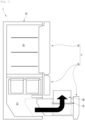
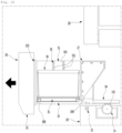
- the refrigerator 1 may have an outer appearance that is defined by a cabinet 1 defining a storage space and a door 2 covering an opened front surface of the cabinet 1.
- the door 2 may be constituted by a rotation door 2 opening and closing the upper space through rotation thereof and a drawer door 3 opening and closing the lower space by being inserted or withdrawn in a drawer type.
- the lower space may be vertically divided again.
- the drawer door 3 may be constituted by an upper drawer door 3 and a lower drawer door 3. Also, an outer appearance of each of the rotation door 2 and the drawer door 3 may be made of a metal material and be exposed to the front side.
- a display 21 may be disposed on one side of a front surface of the rotation door 2.
- the display 21 may have a liquid crystal display structure or a 88 segment structure. Also, when the outer appearance of the door 2 is made of the metal material, a plurality of fine holes are punched in the display 21 to display information by using light passing therethrough.
- a manipulation part 31 may also be provided on the drawer door 3.
- the manipulation part 31 may be disposed on one side of the drawer door 3 that is disposed at the lowermost portion of the drawer door 3.
- the manipulation part 31 may operate in a touch or button manner.
- the manipulation part 31 may be provided as a sensor detecting proximity or movement of a user or provided as an input unit that operates by a user's motion or voice.
- a manipulation device 32 may be disposed on a lower end of the lower drawer door 3 to illuminate an image on a bottom surface and thereby to output a virtual switch and to input an operation in such a manner that the user approaches a corresponding area.
- the automatic insertion and withdrawal and/or automatic elevation of the lower drawer door 3 may be performed by at least one of a plurality of manipulation devices 22, 31, and 32. As necessary, only one of the plurality of manipulation devices 22, 31, and 32 may be provided.
- the lower drawer door 3 will be described in more detail, and also, the lower drawer door 3 will be called a drawer door unless otherwise specified.
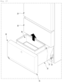
- Fig. 3 is a perspective view illustrating a state in which the container of the drawer door is separated. Also, Fig. 4 is an exploded perspective view of the drawer door.
- the draw-out rail 33 may be provided on a lower end of each of both the side surfaces of the drawer part 32.
- the draw-out rail 33 is disposed on the bottom surface of the drawer part 32.
- the draw-out rail 33 may be provided on the bottom surface of the drawer part 32 and called an under rail.
- the draw-out rail may be disposed on a lower portion or the bottom surface of the drawer part to prevent the draw-out rail from interfering with the elevation device 51 and secure independent operations of the draw-out rail 33 and the elevation device 51.
- the draw-out rack 34 may not be provided on the drawer part 32.
- the user may hold a side of the door part 31 to push and pull the door part 31 so that the drawer door 3 is directly inserted and withdrawn.
- the inside of the drawer part 32 may be divided into a front space S1 and a rear space S2.
- the support member 35 that is vertically elevated and a container seated on the support member 35 to be elevated together with the support member 35 may be disposed in the front space S 1.
- the container 36 is illustrated in the form of a basket having an opened upper portion, the container 36 may have a closed box structure such as a kimchi box. Also, a plurality of containers 36 may be stacked or arranged in parallel to each other.
- the support member 35 is accommodated in the front space S1.
- the support member 35 may be elevated together with the food or container 36 seated on the support member 35 inside the drawer part 32.
- constituents for the elevation of the support member 35 may be disposed on both left and right surfaces of the drawer part 32 and coupled to a central point of both side surfaces of the support member 35 to fix the support member 35 to be elevated without allowing the support member to be lean to one side.
- the food or container 36 accommodated in the support member 35 that is elevated in the front space S1 may be prevented from dropping into the rear space.
- the food or container 36 seated on the support member 35 may be prevented from being separated from the front space S1.
- a separate structure for accommodating may be provided in the rear space S2.
- a rear surface of the door part 31 and a front surface of the drawer part 32 may be coupled to each other.
- power for the elevation of the support member 35 may be provided.
- the elevation assembly (see reference numeral 4 of Fig. 9 ) for the elevation of the support member 35 may be disposed on each of the door part 31 and the drawer part 32.
- the elevation assembly may be selectively connected.
- a protrusion and a groove may be provided on the connection device 6 and the second connection member 522, respectively.
- the protrusion and the groove may have a polygonal shape or a shape that is capable of transmitting the power and be interlocked with each other.
- the connection device 6 and the second connection member 522 may have a different coupling structure in which the power is capable of being transmitted and detachable.
- the door cover 315 may be disposed on the rear surface of the door part 31.
- the door cover 315 may be assembled to be mounted so that the driving device 41 is covered after the driving device 41 is mounted behind the door part 31.
- the door cover 315 may be configured to cover the entire rear surface of the door part 31 or cover only an area corresponding to the driving device 41.
- a pair of door frames 316 may be disposed on the rear surface of the door 2. The coupled state of the door part 31 and the drawer part 32 may be maintained by the door frames 316.
- Fig. 5 is an exploded perspective view illustrating the door part of the drawer door. Also, Fig. 6 is a partial cutaway perspective view of the door part.
- the door part 31 may have an outer appearance that is defined by an outer case 311 defining a front surface and a portion of a circumferential surface, a door liner 314 defining a rear surface, and an upper deco 312 and a lower deco 313 which respectively define top and bottom surfaces. Also, an insulation material may be filled into the door part 31.
- the outer case 311 may be formed by bending a plate-shaped metal material, and an inclined part 311a may be provided on a lower end of a front surface of the outer case 311.
- a manipulation device hole 311b is defined in one side of the inclined part 311a, and the manipulation device 32 for detecting an output of a virtual switch and user's manipulation may be disposed in the manipulation device hole 311b.
- the manipulation device 32 may be constituted by a projector light that outputs an image to be used as a virtual switch and a proximity sensor.
- a manipulation part bracket 313a for the mounting of the manipulation device 32 and an arrangement of a line connected to electrical components within the door part 31 may be provided in the lower deco 313.
- the door liner 314 may be injection-molded by using a plastic material to define the rear surface of the door part 31. Also, the door liner 314 may have a recess part 314a in which the driving device 41 is mounted. The door cover 315 may be mounted on the door liner 314 to cover the driving device 41 mounted on the door part 31 and the recess part 314a.
- a cold air inflow hole 315b may be defined in an upper portion of the door cover 315. At least a portion of the cold air inflow hole 315b may be exposed at a height higher than that of the upper end of the drawer part 32 when the door part 31 and the drawer part 32 are coupled to each other. Thus, a portion of cold air supplied to the drawer part 32 may be introduced into the door cover 315 through the cold air inflow hole 315b. Also, a cold air discharge hole 315c may be defined in a lower portion of the door cover 315. The cold air discharge hole 315c is opened downward between the door part 31 and the drawer part 32. Thus, the cold air introduced into the door cover 315 may flow up to a lower side of the drawer part 32.
- the door cover 315 may provide a flow and circulating path of the cold air at the front of the drawer part 32 therein.
- the cold air may circulate around the drawer part 32 to more efficiently cool the drawer part 32.
- connection device hole 315a may be defined in the rear surface of the door part 31.
- the connection device hole 315a may be defined in the door cover 315.
- the connection device 6 may be exposed to the rear surface of the door part 31 through the connection device hole 315a.
- the connection device 6 may move forward and backward according to the user's manipulation. When the door part 31 and the drawer part 32 are separated from each other by the user's manipulation, the connection device 6 and the power transmission member 52 may be separated from each other.
- the driving device 41 may be provided on the door part 31.
- the driving device 41 may be constitutes disposed in the door part 31 of the elevation assembly 4 and may be called a door-side device.
- the driving device 41 may include the motor assembly 412 configured to provide power and the door-side shaft 413 passing through the motor assembly 412. Also, the driving device 41 may further include the connection device 6. A configuration of each of the constituents of the driving device 41 will be described below in more detail.
- the motor assembly 412 may be disposed in parallel to the front surface of the door part 31 to minimize a recessed depth of the inside of the door part 31, thereby securing insulation performance.
- the door frames 316 may be constituted by a door frame part 316a fixed to the rear surface of the door part 31 and a drawer frame part 316b fixed to the bottom surface of the drawer part 32.
- the door frame part 316a and the drawer frame part 316b may be vertically perpendicular to each other.
- a frame reinforcement part 316c connecting the door frame part 316a to the drawer frame part 316b to prevent the door frames 316 from being deformed may be further provided.
- the door frame part 316a may be mounted on the rear surface of the door part 31 and provided in the door part 31 so that the drawer frame part 316b extends to pass through the rear surface of the door part 31. Also, the drawer frame part 316b may extend backward from a lower end of the door frame part 316a to support the drawer part 32 at a lower side.
- a gasket 317 contacting the front end of the cabinet 1 to seal the storage space may be disposed around the rear surface of the door liner 314.
- Fig. 7 is an exploded perspective view illustrating the drawer part of the drawer door.
- the drawer part 32 may include a drawer body 38 defining an entire shape of the drawer part 32, a drawer-side device 5 provided in the drawer body 38 to constitute the elevation assembly 4, and a plurality of plates 391, 392, and 393 defining an outer appearance of the drawer part 32.
- the drawer body 38 may be injection-molded by using a plastic material and define an entire shape of the drawer part 32.
- the drawer body 38 may have a basket shape having an opened top surface to define a food storage space therein.
- An inclined surface 321 may be disposed on a rear surface of the drawer body 38. Thus, an interference with the machine room 3 may not occur.
- the door frames 316 may be mounted on both sides of the drawer part 32.
- the door frame 316 may be coupled to a lower portion of each of both sides of the bottom surface or both left and right surfaces of the drawer part 32.
- the drawer part 32 and the door part 31 may be integrally coupled to each other and be inserted and withdrawn together with each other.
- the draw-out rack 34 may be disposed on each of both the sides of the bottom surface of the drawer part 32.
- the drawer part 32 may be inserted and withdrawn forward and backward by the draw-out rack 34.
- at least a portion of the rear space S2 is disposed in the lower storage space.
- the draw-out rack 34 may be coupled to a pinion gear 141 disposed on the bottom surface of the storage space.
- the draw-out motor see reference numeral 14 of Fig. 26
- the pinion gear see reference numeral 141 of Fig. 26
- the drawer door 3 may be inserted and withdrawn.
- the drawer door 3 may not be automatically inserted and withdrawn. That is, the user may push or pull the drawer door 3 to be inserted and withdrawn.
- the draw-out rack 34 may be omitted, and thus, the insertion and withdrawal may be performed through only the draw-out rail 33.
- a plurality of reinforcement ribs 381 may extend in vertical and horizontal directions on both left and right sides of the drawer body 38.
- the reinforcement ribs 381 may prevent the drawer body 38 from being deformed by a load applied to both the left and right surfaces of the drawer body.
- the elevation device 51 which is a main component for the elevation of the support member 35, may be disposed on both side surfaces of the drawer body 38.
- the reinforcement ribs 381 may maintain the shape of the drawer body 38, particularly, the drawer part 32 even under the concentrated load.
- a rail mounting part 382 on which the draw-out rail 33 for guiding the insertion and withdrawal of the drawer body 38 is mounted may be disposed on a lower portion of each of both the side surfaces of the drawer body 38.
- the rail mounting part 382 may extend from a front end to a rear end and provide a space in which the draw-out rail 33 is accommodated.
- the draw-out rail 33 may be a rail that extends in multistage.
- the draw-out rail 33 may have one end fixed to the storage space inside the cabinet 1 and the other end fixed to the rail mounting part 382 to more stably realize insertion and the withdrawal of the drawer door 3.
- the rail mounting part 382 may be disposed in an inner region of the drawer flange 38, which will be described below, and may be covered by the outer side plate 391.
- a mounting part 383 on which the elevation device 51 that is a main component is mounted may be recessed inside both the side surfaces of the drawer body 38.
- the mounting part 383 may be recessed outward from the inner surface of the drawer body 38 providing the drawer space.
- the mounting part 383 may extend in the vertical direction.
- the mounting part 383 may vertically extend from the upper end of the drawer body 38 to the bottom surface of the drawer body 38.
- a lower end of the mounting part 383 may be disposed above a lower end of each of both the side surfaces of the drawer body 38.
- the lower end of the mounting part 383 may extend up to the rail mounting part 382.
- the mounting part 383 may not interfere with the draw-out rail 33 and the constitutes for the mounting of the draw-out rail.
- the inner surface of the mounting part 383 may have a shape corresponding to that of the outer surface of the elevation device 51.
- the stably mounted state of the elevation device 51 may be maintained.
- the mounting part 383 may include a first mounting part 383c recessed at a central portion and a second mounting part 383d recessed at each of both sides of the first mounting part 383c.
- the first mounting part 383c may be further recessed than the second mounting part 383d to form a stepped portion between the first mounting part 383c and the second mounting part 383d.
- the elevation device 51 having the corresponding shape may be restricted in the mounted state without rotating.
- the elevation device 51 may be disposed on the same plane as the inner surface of the drawer body 38 in the state of being mounted on the mounting part 383 to prevent the interference when the support member 35 is elevated and provide a sense of unity.
- a bottom surface of the mounting part 383 may support a lower end of the elevation device 51. Also, the top surface of the mounting part 383 may be opened so that the elevation device 51 is inserted through the opened upper side. Here, the elevation device 51 may be inserted to be slid from the upper side so that both ends of the elevation device 51 is restricted within the mounting part 383.
- a mounting part bracket 53 may be disposed on the opened top surface of the mounting part 383.
- the mounting part bracket 53 may be made of a metal material and restrict the upper end of the elevation device 51.
- the mounting part bracket 53 may be mounted on the upper end of each of both the ends of the drawer body 38 to pass through the opened top surface of the mounting part 383.
- the mounting part bracket 53 may be fixed to the upper ends of both side surfaces of the drawer body 38, and simultaneously, the elevation device 51 mounted on the mounting part 383 may be restricted.
- the mounting part bracket 53 may extend from the front end to rear end of each of both the side surfaces of the drawer body 38 and be firmly fixed to the drawer body 38 by a plurality of fixing members.
- the elevation device may be maintained in the state of being more stably and firmly mounted on the drawer body 38.
- the elevation device 51 may be connected to both ends of the support member 35 by the connecting bracket 54. Also, the elevation device 51 may operate to allow the support member 35 to vertically move and guide smooth vertical movement of the support member 35.
- the transmission member mounting part 384 may be opened outward from the upper end of each of both the side surfaces of the drawer body 38 to communicate with the mounting part 383.
- the power transmission member 52 mounted on the transmission member mounting part 384 may be coupled to the elevation device 51 mounted on the mounting part 383 to transmit the power.
- the mounting part 383 may have a shape that is recessed from the inner surface of the drawer body 38, and the transmission member mounting part 384 may have a shape that is recessed from the outer surface of the drawer body 38.
- a mold may have a simple structure so that the drawer body 38 is easily molded.
- the mounting part 383 and the transmission member mounting part 384 may be disposed inside a region of the drawer flange 38 that is bent outward from an upper end of each of both side surfaces of the drawer body 38. That is, the mounting part 383 and the transmission member mounting part 384 may be disposed below the region in which the drawer flange 38 is bent outward. Also, in addition to the mounting part 383, the transmission member mounting part 384, and the rail mounting part 382, the elevation device 51 and the power transmission member 52, which are mounted on the mounting part 383 and the transmission member mounting part 384, may not also protrude inward or outward from the drawer flange 38.
- all of the drawer-side device 5 constituting a portion of the elevation assembly 4 and the structure for mounting the drawer-side device 5 may be disposed in the region of the drawer flange 38. Thus, a loss of the storage space inside the drawer body 38 may be prevented from occurring.
- the support member 35 of the drawer-side device 5 and the elevation device 51 may be disposed on the inner surface of the drawer body 38, and the power transmission member 52 may be disposed outside the drawer body 38. Also, the mounting part 383 and the transmission member mounting part 384 may communicate with each other, and the power transmission member 52 and the elevation device 51 may be connected to each other in the state of being mounted on the drawer body 38.
- the plurality of plates 391, 392, and 393 made of a plate-shaped metal material such as stainless steel to define at least portions of the inside and outside of the drawer body 38 may be provided on the drawer body 38.
- the outer side plate 391 may be disposed on each of both left and right surfaces of the outside of the drawer body 38.
- the outer side plate 391 may be mounted on each of both the left and right surfaces of the drawer body 38 to define an outer appearance of each of both the side surfaces.
- the constituents such as the power transmission member 52 and the draw-out rail 33, which are mounted on both the sides of the drawer body 38 may not be exposed to the outside.
- an upper bent part 391a may be disposed on an upper end of the outer side plate 391.
- the upper bent part 391a may cover the upper end of each of both the side surfaces of the drawer body 38 and the mounting part bracket 53.
- An inner side plate 392 may be disposed on each of both left and right surfaces of the inside of the drawer body 38.
- the inner side plate 392 may be mounted on each of both the side surfaces of the drawer body 38 to define both the left and right surfaces of the inside thereof.
- An extending end of the upper bent part 391a may contact the upper end of the inner side plate 391.
- all of the inside and outside and the top surface of both the left and right surfaces of the drawer body 38 may be covered by the inner side plate 392 and the outer side plate 391.
- a side opening 394 having a size corresponding to the mounting part 383 may be defined in the inner side plate 392.
- An inner plate 395 may be disposed on each of front, bottom, and rear surfaces of the inside of the drawer body 38.
- the inner plate 395 may be constituted by a front surface part 395a, a bottom surface part 395b, and a rear surface part 395c, which have sizes correspond to the front surface, the bottom surface, and the rear surface of the inside of the drawer body 38.
- the inner plate 395 may be provided by bending the plate-shaped stainless material so that the inner plate 395 defines the inner surface of the remaining portion except for both the left and right surfaces of the drawer body 38. Also, both left and right ends of the inner plate 395 may contact the inner side plate 392.
- the front surface part 395a, the bottom surface part 395b, and the rear surface part 395c constituting the inner plate 395 may be separately provided and then coupled to or contact each other.
- the entire inner surfaces of the drawer body 38 may be defined by the inner side plate 392 and the inner plate 395, and the inner surface of the drawer body 38 may provide texture of the metal.
- the inner surface of the drawer part 32 may more easily transfer heat by the inner side plate 392 and the inner plate 395, and thus, the entire drawer part 32 may be uniformly cooled by the surrounding cold air.
- the foods accommodated in the drawer part 32 may be more uniformly cooled and thus stored at a low temperature in the more uniform region.
- visually excellent cooling performance and storage performance may be provided to the user.
- upper bent parts 395d and 395e that are bent outward may be further disposed on the front surface part 395a and the rear surface part 395c of the inner plate 395 to cover the top surfaces of the front end and the rear end of the drawer body 38, respectively.
- the rear surface part 395c may have a shape corresponding to the inclined surface 321 of the rear surface of the drawer body 38 and thus be closely attached to the inclined surface 321.
- a bottom surface opening 395f may be further defined in the rear end of the bottom surface part 395b adjacent to the lower end of the rear surface part 395c.
- the bottom surface opening 395f may be opened at a position corresponding to a cover support part 388 protruding from the bottom surface of the drawer body.
- the cover support part 388 may be exposed through the bottom surface opening 395f.
- the lower end of the drawer cover 37 may be coupled to the cover support part 388 so that the drawer cover 37 is mounted.
- the drawer cover 37 may include a cover front part 371 that partitions the inside of the drawer body 38 into a front space S1 and a rear space S2 and a cover top surface part 372 bent from an upper end of the cover front part 371 to cover a top surface of the rear space S2.
- the drawer cover 37 when the drawer cover 37 is mounted, only the front space S1, in which the support member 35 is disposed, may be exposed in the drawer body 38, and the rear space S2 may be covered by the drawer cover 37.
- a lower end of the cover front part 371 may be coupled to the cover support part 388.
- a plurality of cover restriction parts 373 may be disposed along both the left and right ends of the drawer cover 37.
- the cover restriction part 373 may be disposed at a position corresponding to a plurality of cover restriction protrusions 385 protruding inward from the inner surface of the drawer body 38.
- Each of the cover restriction protrusions 385 may pass through a protrusion hole 392b defined in the inner side plate 392 to protrude.
- cover restriction part 373 may be press-fitted into the cover restriction protrusion 385.
- the cover restriction protrusion 385 may be coupled to the cove restriction part 373 to fix the drawer cover 37.
- the support member 35 may be provided in the drawer body 38.
- the support member 35 may include one component of the elevation assembly 4.
- the support member 35 may have a size that is enough to be accommodated in the front space S1 of the bottom surface of the drawer body 38.
- the support member 35 may have a plate shape as illustrated in Fig. 3 .
- the support member 35 may include an elevation plate 351 supporting the food or container and an elevation frame 352 supporting the elevation plate 351 at a lower side and reinforcing strength of the elevation plate 351.
- the support member 35 may be a portion on which the food or container 36 is substantially seated and supported and thus may be called a seating member or a tray.
- the support member 35 may be provided as one of the elevation plate 351 or the elevation frame 352.
- the elevation plate 351 may have a rectangular plate shape and also protrude upward along the circumference and contact a circumference of the bottom surface of the container 36 to prevent the container 36 from moving.
- the connecting bracket 54 may have one side fixed to the elevation frame 352 and the other side coupled to the elevation device 51. Thus, when the elevation device 51 operates, the elevation frame 352 connected to the connecting bracket 54, i.e., the support member 35 may vertically move together with the connecting bracket 54.
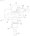
- Fig. 8 is an exploded perspective view illustrating a coupling structure between the elevation assembly and the support member of the refrigerator.
- a shaft gear 572 may be disposed on an upper portion of the elevation shaft 57, i.e., an upper end of the screw thread 571.
- the shaft gear 572 may be disposed above an end of the screw thread 571 and be integrally coupled to the elevation shaft 57 to rotate together with the elevation shaft 57.
- the shaft gear 572 may be gear-coupled to the power transmission member 52 in the state of perpendicularly crossing the transmission gear 523 mounted on the power transmission member 52.
- the shaft fixing member 524 may be disposed on the power transmission member 52.
- the shaft fixing member 524 may be provided on both right and left sides of the drawer part 32.
- a shaft fixing member 524 may be mounted on the transmission member mounting part 384 to allow the power transmission member 52 to rotate without being tilted or moving.
- the door part 31 and the drawer part 32 may be coupled to and separated from each other.
- the power transmission member 52 may be separated from the driving device 41 by manipulating the connection device 6.
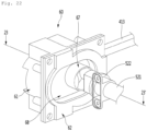
- Fig. 18 is a perspective view of the door before the connection device is manipulated. Also,
- Fig. 19 is a view illustrating a state before the connection device is manipulated. Also, Fig. 2 is a cross-sectional view of Fig. 19 .
- one side of the door cover 315 and a portion of the connection device 6 may be exposed through the rear surface of the door part 31 or a space between the door part 31 and the drawer part 32.
- At least a portion of the push member 68 for the user's manipulation may be disposed on one side of the door part 31 exposed between the door part 31 and the drawer part 32 or to the outside of the drawer part 32 so as to be manipulated by the user.
- the push member 68 may be disposed so as to be exposed through the outer surface of the door cover 315 in the state of protruding to the outside of the connection device cover 62.
- the user may confirm the coupled state of the first connection member 67 and the second connection member 522 through the protruding state of the push member 68.
- the user may input an operation for manipulating the elevation device 51, and the elevation of the support member 35 in the drawer part 32 may be performed.
- Fig. 21 is a perspective view of the door during the manipulation of the connection device.
- Fig. 22 is a view illustrating a communication state between the refrigerator and an oven.
- Fig. 23 is a cross-sectional view of Fig. 22 .
- connection device 6 may be manipulated to separate the door part 31 and the drawer part 32 from each other.
- an operation of releasing the restriction before and after the manipulation of the connection device 6 may be additionally performed.
- the drawer part 32 and the door frame 316 may be separated from each other, and then the door part 31 may be manipulated by manipulating the connection device 6 to completely separating the door part 31 and the drawer part 32 from each other.
- the elevation assembly 4 may also separate the door-side device 41 provided in the door part 31 and the drawer-side device 5 disposed in the drawer part 32 from each other.
- the user may press the push member 68 on both sides exposed through the rear surface of the door part 31 as shown in F21. 21 and press the push member 68 to push the elastic member 66, and the first connection member 67 may move together with the push member 68 to the inside of the connection device 6.
- the user may prevent electric shock by the electric device in the state in which the door part 31 and the drawer part 32 are separated from each other and prevent the electric device from being damaged during the cleaning.
- the door part 31 and the drawer part 32 may be coupled to each other when the door part 31 and the drawer part 32 are separated from each other.
- the first connection part 673 and the second connection part 522a may be aligned by the coupling of the door frame 316 and the drawer part 32.
- the connection device 6 and the power transmission member 52 may be connected to each other without performing a separate manipulation process.
- Fig. 24 is a perspective view illustrating a state in which the drawer door is closed.
- the refrigerator 1 in the state in which the food is stored, the refrigerator 1 may be maintained in a state in which all of the rotation door 2 and the drawer door 3 are closed. In this state, the user may withdraw the drawer door 3 to accommodate the food.
- the drawer door 3 may be configured to be inserted and withdrawn by the driving of the draw-out motor 14, not by a method of directly pulling the drawer door 3 by the user.
- the draw-out rack 34 provided on the bottom surface of the drawer door 3 may be coupled to the pinion gear 141 rotating when the draw-out motor 14 provided in the cabinet 1 is driven.
- the drawer door 3 may be inserted and withdrawn according to the driving of the draw-out motor 14.
- a switch may be provided at each of positions at which the drawer door 3 is completely inserted and withdrawn to detect the draw-out state of the drawer door 3.
- the draw-out state of the drawer door 3 may be detected by counting the rotation number of draw-out motor 14 or measuring a distance between the rear surface of the door part 31 and the front end of the cabinet 1.
- the support member 35 may ascend to prevent the container 36 or the stored food seated on the support member 35 from interfering with the doors 2 and 3 or the cabinet 1.
- the ascending of the support member 35 may start in a state in which the drawer door 3 is completely withdrawn. Also, to secure the user's safety and prevent the food from being damaged, the ascending of the support member 35 may start after a set time elapses after the drawer door 3 is completely withdrawn.
- the user may manipulate the manipulation part 31 to input the ascending of the support member 35. That is, the manipulation part 31 may be manipulated to withdraw the drawer door 3, and the manipulation part 31 may be manipulated again to elevate the support member 35. Also, the drawer door 3 may be manually inserted and withdrawn by a user's hand. After the drawer door 3 is withdrawn, the manipulation part 31 is manipulated to elevate the support member 35.
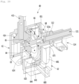
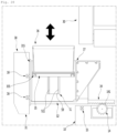
- Fig. 27 is a perspective view illustrating a state in which the support member of the drawer door is completely elevated.
- Fig. 28 is a cross-sectional view of the drawer door in the state of Fig. 27 .
- the elevation of the support member 35 may be performed in the state in which the drawer door 3 is withdrawn.
- the support member 35 may be elevated by the operation of the driving motor 411.
- the power may be transmitted to elevate the support member 35.
- the driving shafts 413 connected to the driving motor 411 may rotate, and also the first gear 414 and the second gear 415 connected to the driving shaft 413 may rotate.
- the rotation force of the driving device 41 may be transmitted to the drawer-side device 5 by connection device 6 and the second member 522, which are coupled to each other.
- the rotation force transmitted from the driving device 41 may allow the power transmission member 52 and the transmission gear 523 of the end of the power transmission member 52 to rotate.
- the rotation force may be transmitted in the state in which the transmission gear 523 and the shaft gear 572 are connected to each other, and the rotation force of the power transmission member 52 may allow the elevation shaft 57 to rotate. Due to the rotation of the elevation shaft 57, the elevation block 567 and the block holder 56 may move upward along the elevation shaft 57. Here, all of the portions of the elevation device 51, which is exposed to the inside of the drawer part 32, may be covered by the rail cover 59. Also, the block holder 56 may vertically move along the guide slit 511 defined by the rail cover 59.
- the support member 35 may continuously ascend by a sufficient height so that the user is accessible to the food or container 36 seated on the support member 35. Thus, the user may easily lift the food or container.
- the support member 35 may ascend until the block holder 56 is disposed at the upper end of the guide slit. When the ascending of the support member 35 is completed, the driving of the driving motor 411 is stopped.
- a height detection device 16 for detecting a position of the support member 35 may be provided.
- the height detection device 16 may be provided in the door part 31 at a height corresponding to the uppermost ascending position of the support member 35 and the lowermost descending position of the support member 35.
- the driving of the driving motor 411 is stopped in the state in which the support member 35 maximally ascends.
- the support member 35 is disposed inside the drawer part 32
- the food or container 36 seated on the support member 35 may be disposed at a position higher than the opened top surface of the drawer part 32.
- the user may easily access the food or container 36.
- the user may allow the support member 35 to descend by manipulating the manipulation part 31.
- the descending of the support member 35 may be performed by reverse rotation of the driving motor 411 and may be gradually performed through the reverse procedure with respect to the above-described procedure.
- the completion of the descending of the support member 35 may be performed by the height detection device 16.
- the height detection device 16 may be further provided at a position that detects the magnet disposed on the support member 35 when the support member 35 is disposed at the lowermost descending position.
- the drawer door 3 may be inserted.
- the drawer door 3 may be closed by the user's manipulation or by the driving of the draw-out motor 14.
- a state of Fig. 16 may become.
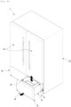
- Fig. 29 is a perspective view of a refrigerator according to another embodiment.
- a refrigerator 1 may include a cabinet 1 having a storage space that is vertically partitioned and a door 2 opening and closing the storage space.
- the door 2 may include a pair of rotation doors 2 which are provided in an upper portion of a front surface of the cabinet 1 to open and close an upper storage space and a drawer door 3 disposed in a lower portion of the front surface of the cabinet 1 to open and close a lower storage space.
- the drawer door 3 may be inserted and withdrawn forward and backward like the foregoing embodiment. In the state in which the drawer door 3 is withdrawn, the support member 35 within the drawer door 3 may be vertically elevated.
- a manipulation part 31 or a manipulation device 32 may be provided at one side of the door part 31.
- the insertion and withdrawal of the drawer door 3 and/or the elevation of the support member 35 may be realized by manipulating the manipulation part 31 or the manipulation device 32.
- the support member 35 may be provided in the drawer part 32.
- the support member 35 may be elevated by driving the elevation assembly provided in the door part 31 and the drawer part 32. Since the structure of the drawer door 3 and the structure of the elevation assembly 4 are the same as those according to the foregoing embodiment, their detailed descriptions will be omitted.
- a plurality of containers 361 may be provided in the support member 35.
- the container 361 may be a sealed container such as a kimchi passage, and a plurality of the containers 361 may be seated on the support member 35.
- the container 361 may be elevated together with the support member 35 when the support member 35 is elevated. Thus, in the state in which the container 361 ascends, at least a portion of the drawer part 32 may protrude, and thus, the user may easily lift the container 361.
- the support member 35 may interfere with the rotation door 2 in the rotation door 2 is opened even though the drawer door 3 is withdrawn. Thus, the support member 35 may ascend in a state in which the rotation door 2 is closed. For this, a door switch for detecting the opening/closing of the rotation door 2 may be further provided.
- Fig. 3 is a perspective view of a refrigerator according to another embodiment.
- a refrigerator 1 includes a cabinet 1 defining a storage space therein and a door 2 opening and closing an opened front surface of the cabinet 1, which define an outer appearance of the refrigerator 1.
- the door 2 may include a rotation door 2 which is provided in an upper portion of the cabinet 1 to open and close the upper storage space and a drawer door 2 disposed in a lower portion of the cabinet 1 to open and close the lower storage space.
- the lower space of the cabinet may be divided into left and right spaces.
- the drawer door 3 may be provided in a pair so that the pair of drawer doors 3 respectively open and close the lower spaces.
- the pair of drawer doors 3 may be disposed in parallel to each other at left and right sides.
- the drawer doors 3 may have the same structure.
- the drawer door 3 may have the same structure as the drawer door according to the foregoing embodiment. Thus, the drawer door 3 may be inserted and withdrawn by user's manipulation. In the drawer door 3 is withdrawn, the support member 35 may ascend so that a user more easily accesses a food or container within the drawer door 3.
- the portion of the storage space within the drawer door may be elevated in the state in which the drawer door is withdrawn.
- the user may not excessively turn its back to improve the convenience in use.
- the support member on which the food or the container is seated may be disposed in the drawer door, and the elevation assembly may be provided on both the sides of the drawer door to elevate the support member.
- the support member may be elevated in the state in which both ends of the support member are supported.
- the support member may be prevented from being eccentric or tilted to secure the stable elevation and the operation reliability.
- the support member may constitute a portion of the space within the drawer part and be disposed in the front space of the drawer part to elevate the support member in the state in which the drawer part is withdrawn so that only the front space is disposed to the outside without withdrawing the entire drawer part.
- the drawer door may include the door part defining the front surface of the door and the drawer part defining the accommodation space, and the door part and the drawer part may be coupled to be separated from each other.
- the elevation assembly may include the door-side device provided in the door part and the drawer-side device provided in the drawer part.
- the door-side device and the drawer-side device may be connected to each other to transmit the power.
- the assemblability and the service performance of the drawer door may be improved.
- connection device on the rear surface of the door may be manipulated to simply separate the driving device of the door part from the elevation device of the drawer part, and the driving device and the elevation device may be separated from each other through the simple manipulation without using the separate mechanism or performing the separate separation process. Furthermore, the door part and the drawer part may be easily separated from each other.
Landscapes
- Engineering & Computer Science (AREA)
- Mechanical Engineering (AREA)
- Chemical & Material Sciences (AREA)
- Combustion & Propulsion (AREA)
- Physics & Mathematics (AREA)
- Thermal Sciences (AREA)
- General Engineering & Computer Science (AREA)
- Life Sciences & Earth Sciences (AREA)
- Geology (AREA)
- Structural Engineering (AREA)
- Refrigerator Housings (AREA)
Priority Applications (1)
| Application Number | Priority Date | Filing Date | Title |
|---|---|---|---|
| EP25157595.7A EP4530561B1 (fr) | 2018-03-30 | 2019-03-18 | Réfrigérateur |
Applications Claiming Priority (3)
| Application Number | Priority Date | Filing Date | Title |
|---|---|---|---|
| KR1020180037249A KR102510855B1 (ko) | 2018-03-30 | 2018-03-30 | 냉장고 |
| EP20201813.1A EP3798557B1 (fr) | 2018-03-30 | 2019-03-18 | Réfrigérateur |
| EP19163397.3A EP3546866B1 (fr) | 2018-03-30 | 2019-03-18 | Réfrigérateur |
Related Parent Applications (3)
| Application Number | Title | Priority Date | Filing Date |
|---|---|---|---|
| EP20201813.1A Division-Into EP3798557B1 (fr) | 2018-03-30 | 2019-03-18 | Réfrigérateur |
| EP20201813.1A Division EP3798557B1 (fr) | 2018-03-30 | 2019-03-18 | Réfrigérateur |
| EP19163397.3A Division EP3546866B1 (fr) | 2018-03-30 | 2019-03-18 | Réfrigérateur |
Related Child Applications (2)
| Application Number | Title | Priority Date | Filing Date |
|---|---|---|---|
| EP25157595.7A Division EP4530561B1 (fr) | 2018-03-30 | 2019-03-18 | Réfrigérateur |
| EP25157595.7A Division-Into EP4530561B1 (fr) | 2018-03-30 | 2019-03-18 | Réfrigérateur |
Publications (4)
| Publication Number | Publication Date |
|---|---|
| EP4269918A2 true EP4269918A2 (fr) | 2023-11-01 |
| EP4269918A3 EP4269918A3 (fr) | 2024-01-03 |
| EP4269918C0 EP4269918C0 (fr) | 2025-05-07 |
| EP4269918B1 EP4269918B1 (fr) | 2025-05-07 |
Family
ID=65818299
Family Applications (4)
| Application Number | Title | Priority Date | Filing Date |
|---|---|---|---|
| EP23181040.9A Active EP4269918B1 (fr) | 2018-03-30 | 2019-03-18 | Réfrigérateur |
| EP20201813.1A Active EP3798557B1 (fr) | 2018-03-30 | 2019-03-18 | Réfrigérateur |
| EP19163397.3A Active EP3546866B1 (fr) | 2018-03-30 | 2019-03-18 | Réfrigérateur |
| EP25157595.7A Active EP4530561B1 (fr) | 2018-03-30 | 2019-03-18 | Réfrigérateur |
Family Applications After (3)
| Application Number | Title | Priority Date | Filing Date |
|---|---|---|---|
| EP20201813.1A Active EP3798557B1 (fr) | 2018-03-30 | 2019-03-18 | Réfrigérateur |
| EP19163397.3A Active EP3546866B1 (fr) | 2018-03-30 | 2019-03-18 | Réfrigérateur |
| EP25157595.7A Active EP4530561B1 (fr) | 2018-03-30 | 2019-03-18 | Réfrigérateur |
Country Status (4)
| Country | Link |
|---|---|
| US (4) | US10648727B2 (fr) |
| EP (4) | EP4269918B1 (fr) |
| KR (3) | KR102510855B1 (fr) |
| CN (1) | CN110319646B (fr) |
Families Citing this family (6)
| Publication number | Priority date | Publication date | Assignee | Title |
|---|---|---|---|---|
| EP4664041A3 (fr) * | 2017-12-29 | 2026-03-04 | LG Electronics Inc. | Réfrigérateur |
| KR102510856B1 (ko) * | 2018-03-26 | 2023-03-15 | 엘지전자 주식회사 | 냉장고 |
| KR102510855B1 (ko) * | 2018-03-30 | 2023-03-15 | 엘지전자 주식회사 | 냉장고 |
| KR102492728B1 (ko) | 2018-05-08 | 2023-01-27 | 엘지전자 주식회사 | 냉장고 |
| KR102595327B1 (ko) * | 2018-08-30 | 2023-10-30 | 엘지전자 주식회사 | 냉장고 |
| US12018881B2 (en) * | 2020-11-23 | 2024-06-25 | Whirlpool Corporation | Adjustment assembly for appliance door |
Citations (2)
| Publication number | Priority date | Publication date | Assignee | Title |
|---|---|---|---|---|
| KR20060053420A (ko) | 2004-11-15 | 2006-05-22 | 엘지전자 주식회사 | 냉장고 |
| KR20080101335A (ko) | 2007-05-17 | 2008-11-21 | 삼성전자주식회사 | 냉장고 |
Family Cites Families (30)
| Publication number | Priority date | Publication date | Assignee | Title |
|---|---|---|---|---|
| US210212A (en) * | 1878-11-26 | Improvement in horse-detachers | ||
| CA2364217C (fr) * | 2000-11-29 | 2005-10-25 | Faubion Associates, Inc. | Appareil de securite d'une vitrine d'exposition |
| US6494150B1 (en) * | 2001-03-02 | 2002-12-17 | Precision Lifts Of Deerfield Beach, Incorporated | Elevating apparatus for visual displays |
| AU2004242445B2 (en) * | 2004-07-16 | 2006-02-02 | Lg Electronics Inc | Refrigerator having basket lift apparatus |
| KR100652583B1 (ko) * | 2004-07-29 | 2006-12-06 | 엘지전자 주식회사 | 바스켓 승강장치를 구비한 냉장고 |
| KR100690647B1 (ko) * | 2004-07-29 | 2007-03-09 | 엘지전자 주식회사 | 바스켓 승강장치를 구비한 냉장고 |
| KR100690649B1 (ko) * | 2004-08-26 | 2007-03-09 | 엘지전자 주식회사 | 바스켓 승강장치를 구비한 냉장고 |
| KR100700777B1 (ko) | 2005-03-02 | 2007-03-27 | 엘지전자 주식회사 | 냉장고 및 냉장고의 바스켓 구동장치 |
| EP1775536A3 (fr) * | 2005-10-17 | 2013-01-23 | Samsung Electronics Co., Ltd. | Réfrigérateur |
| US8061790B2 (en) | 2007-12-20 | 2011-11-22 | General Electric Company | Powered drawer for an appliance |
| KR101787095B1 (ko) * | 2009-07-07 | 2017-10-18 | 엘지전자 주식회사 | 냉장고 |
| DE102009029142A1 (de) * | 2009-09-02 | 2011-03-03 | BSH Bosch und Siemens Hausgeräte GmbH | Kältegerät mit herausziehbarer Schale |
| KR20110024883A (ko) * | 2009-09-03 | 2011-03-09 | 삼성전자주식회사 | 도어자동개폐장치 및 이를 구비한 냉장고 |
| CN102155840B (zh) * | 2011-04-22 | 2013-07-03 | 合肥美的荣事达电冰箱有限公司 | 一种抽屉组件和具有其的冰箱 |
| CN102226626B (zh) * | 2011-04-22 | 2013-07-03 | 合肥美的荣事达电冰箱有限公司 | 用于冰箱的控制方法 |
| US9377238B2 (en) * | 2013-03-14 | 2016-06-28 | Electrolux Home Products, Inc. | Refrigerator with a scissor-type lift mechanism |
| US9107494B2 (en) * | 2013-03-14 | 2015-08-18 | Electrolux Home Products, Inc. | Refrigerator with a lift mechanism including at least one pivot arm |
| US20140265798A1 (en) * | 2013-03-14 | 2014-09-18 | Electrolux Home Products, Inc. | Direct drive rack & pinion lift mechanism for refrigerated storage bin |
| WO2018088802A1 (fr) * | 2016-11-10 | 2018-05-17 | Samsung Electronics Co., Ltd. | Dispositif de levage et réfrigérateur le comprenant |
| KR102289689B1 (ko) * | 2017-03-10 | 2021-08-13 | 삼성전자주식회사 | 승강장치 및 이를 갖는 냉장고 |
| EP4664041A3 (fr) * | 2017-12-29 | 2026-03-04 | LG Electronics Inc. | Réfrigérateur |
| KR20190109069A (ko) * | 2018-03-16 | 2019-09-25 | 엘지전자 주식회사 | 냉장고 |
| KR102640307B1 (ko) * | 2018-03-26 | 2024-02-22 | 엘지전자 주식회사 | 냉장고 |
| KR102464922B1 (ko) * | 2018-03-26 | 2022-11-08 | 엘지전자 주식회사 | 냉장고 |
| KR102510855B1 (ko) * | 2018-03-30 | 2023-03-15 | 엘지전자 주식회사 | 냉장고 |
| KR102492728B1 (ko) * | 2018-05-08 | 2023-01-27 | 엘지전자 주식회사 | 냉장고 |
| KR102474912B1 (ko) * | 2018-06-11 | 2022-12-06 | 엘지전자 주식회사 | 냉장고 |
| KR102586889B1 (ko) * | 2018-08-30 | 2023-10-06 | 엘지전자 주식회사 | 냉장고 |
| KR102596480B1 (ko) * | 2018-10-19 | 2023-11-01 | 엘지전자 주식회사 | 냉장고 |
| KR102579883B1 (ko) * | 2018-12-28 | 2023-09-18 | 엘지전자 주식회사 | 냉장고 |
-
2018
- 2018-03-30 KR KR1020180037249A patent/KR102510855B1/ko active Active
- 2018-12-21 US US16/230,902 patent/US10648727B2/en active Active
-
2019
- 2019-03-01 CN CN201910157223.1A patent/CN110319646B/zh active Active
- 2019-03-18 EP EP23181040.9A patent/EP4269918B1/fr active Active
- 2019-03-18 EP EP20201813.1A patent/EP3798557B1/fr active Active
- 2019-03-18 EP EP19163397.3A patent/EP3546866B1/fr active Active
- 2019-03-18 EP EP25157595.7A patent/EP4530561B1/fr active Active
-
2020
- 2020-04-08 US US16/843,481 patent/US11105551B2/en active Active
-
2021
- 2021-07-26 US US17/385,103 patent/US11867453B2/en active Active
-
2022
- 2022-11-25 KR KR1020220160742A patent/KR102640808B1/ko active Active
-
2023
- 2023-12-01 US US18/526,689 patent/US12535265B2/en active Active
-
2024
- 2024-02-20 KR KR1020240024425A patent/KR102790991B1/ko active Active
Patent Citations (2)
| Publication number | Priority date | Publication date | Assignee | Title |
|---|---|---|---|---|
| KR20060053420A (ko) | 2004-11-15 | 2006-05-22 | 엘지전자 주식회사 | 냉장고 |
| KR20080101335A (ko) | 2007-05-17 | 2008-11-21 | 삼성전자주식회사 | 냉장고 |
Also Published As
| Publication number | Publication date |
|---|---|
| EP3546866A1 (fr) | 2019-10-02 |
| KR102790991B1 (ko) | 2025-04-07 |
| US20190301789A1 (en) | 2019-10-03 |
| US20240102726A1 (en) | 2024-03-28 |
| EP3798557B1 (fr) | 2023-08-02 |
| CN110319646B (zh) | 2021-02-05 |
| KR102640808B1 (ko) | 2024-02-23 |
| EP3546866B1 (fr) | 2020-11-25 |
| KR102510855B1 (ko) | 2023-03-15 |
| KR20220165682A (ko) | 2022-12-15 |
| US10648727B2 (en) | 2020-05-12 |
| KR20240027657A (ko) | 2024-03-04 |
| EP4530561A3 (fr) | 2025-06-11 |
| CN110319646A (zh) | 2019-10-11 |
| KR20190114478A (ko) | 2019-10-10 |
| EP4269918C0 (fr) | 2025-05-07 |
| US12535265B2 (en) | 2026-01-27 |
| EP4269918B1 (fr) | 2025-05-07 |
| EP4530561A2 (fr) | 2025-04-02 |
| US20210348833A1 (en) | 2021-11-11 |
| EP4530561B1 (fr) | 2025-12-31 |
| EP3798557A1 (fr) | 2021-03-31 |
| US11105551B2 (en) | 2021-08-31 |
| US11867453B2 (en) | 2024-01-09 |
| EP4269918A3 (fr) | 2024-01-03 |
| US20200232702A1 (en) | 2020-07-23 |
Similar Documents
| Publication | Publication Date | Title |
|---|---|---|
| US11898794B2 (en) | Refrigerator | |
| US11002478B2 (en) | Refrigerator | |
| US11486634B2 (en) | Refrigerator | |
| US10465970B1 (en) | Refrigerator | |
| EP3546866B1 (fr) | Réfrigérateur | |
| US11047618B2 (en) | Refrigerator | |
| EP4368799A2 (fr) | Réfrigérateur |
Legal Events
| Date | Code | Title | Description |
|---|---|---|---|
| PUAI | Public reference made under article 153(3) epc to a published international application that has entered the european phase |
Free format text: ORIGINAL CODE: 0009012 |
|
| STAA | Information on the status of an ep patent application or granted ep patent |
Free format text: STATUS: REQUEST FOR EXAMINATION WAS MADE |
|
| 17P | Request for examination filed |
Effective date: 20230622 |
|
| AC | Divisional application: reference to earlier application |
Ref document number: 3546866 Country of ref document: EP Kind code of ref document: P Ref document number: 3798557 Country of ref document: EP Kind code of ref document: P |
|
| AK | Designated contracting states |
Kind code of ref document: A2 Designated state(s): AL AT BE BG CH CY CZ DE DK EE ES FI FR GB GR HR HU IE IS IT LI LT LU LV MC MK MT NL NO PL PT RO RS SE SI SK SM TR |
|
| PUAL | Search report despatched |
Free format text: ORIGINAL CODE: 0009013 |
|
| AK | Designated contracting states |
Kind code of ref document: A3 Designated state(s): AL AT BE BG CH CY CZ DE DK EE ES FI FR GB GR HR HU IE IS IT LI LT LU LV MC MK MT NL NO PL PT RO RS SE SI SK SM TR |
|
| RIC1 | Information provided on ipc code assigned before grant |
Ipc: F25D 25/02 20060101AFI20231124BHEP |
|
| GRAP | Despatch of communication of intention to grant a patent |
Free format text: ORIGINAL CODE: EPIDOSNIGR1 |
|
| STAA | Information on the status of an ep patent application or granted ep patent |
Free format text: STATUS: GRANT OF PATENT IS INTENDED |
|
| INTG | Intention to grant announced |
Effective date: 20241024 |
|
| GRAS | Grant fee paid |
Free format text: ORIGINAL CODE: EPIDOSNIGR3 |
|
| GRAA | (expected) grant |
Free format text: ORIGINAL CODE: 0009210 |
|
| STAA | Information on the status of an ep patent application or granted ep patent |
Free format text: STATUS: THE PATENT HAS BEEN GRANTED |
|
| AC | Divisional application: reference to earlier application |
Ref document number: 3546866 Country of ref document: EP Kind code of ref document: P Ref document number: 3798557 Country of ref document: EP Kind code of ref document: P |
|
| AK | Designated contracting states |
Kind code of ref document: B1 Designated state(s): AL AT BE BG CH CY CZ DE DK EE ES FI FR GB GR HR HU IE IS IT LI LT LU LV MC MK MT NL NO PL PT RO RS SE SI SK SM TR |
|
| REG | Reference to a national code |
Ref country code: GB Ref legal event code: FG4D |
|
| REG | Reference to a national code |
Ref country code: CH Ref legal event code: EP |
|
| REG | Reference to a national code |
Ref country code: DE Ref legal event code: R096 Ref document number: 602019069851 Country of ref document: DE |
|
| REG | Reference to a national code |
Ref country code: IE Ref legal event code: FG4D |
|
| U01 | Request for unitary effect filed |
Effective date: 20250528 |
|
| U07 | Unitary effect registered |
Designated state(s): AT BE BG DE DK EE FI FR IT LT LU LV MT NL PT RO SE SI Effective date: 20250606 |
|
| PG25 | Lapsed in a contracting state [announced via postgrant information from national office to epo] |
Ref country code: ES Free format text: LAPSE BECAUSE OF FAILURE TO SUBMIT A TRANSLATION OF THE DESCRIPTION OR TO PAY THE FEE WITHIN THE PRESCRIBED TIME-LIMIT Effective date: 20250507 |
|
| PG25 | Lapsed in a contracting state [announced via postgrant information from national office to epo] |
Ref country code: GR Free format text: LAPSE BECAUSE OF FAILURE TO SUBMIT A TRANSLATION OF THE DESCRIPTION OR TO PAY THE FEE WITHIN THE PRESCRIBED TIME-LIMIT Effective date: 20250808 Ref country code: NO Free format text: LAPSE BECAUSE OF FAILURE TO SUBMIT A TRANSLATION OF THE DESCRIPTION OR TO PAY THE FEE WITHIN THE PRESCRIBED TIME-LIMIT Effective date: 20250807 |
|
| PG25 | Lapsed in a contracting state [announced via postgrant information from national office to epo] |
Ref country code: PL Free format text: LAPSE BECAUSE OF FAILURE TO SUBMIT A TRANSLATION OF THE DESCRIPTION OR TO PAY THE FEE WITHIN THE PRESCRIBED TIME-LIMIT Effective date: 20250507 |
|
| PG25 | Lapsed in a contracting state [announced via postgrant information from national office to epo] |
Ref country code: HR Free format text: LAPSE BECAUSE OF FAILURE TO SUBMIT A TRANSLATION OF THE DESCRIPTION OR TO PAY THE FEE WITHIN THE PRESCRIBED TIME-LIMIT Effective date: 20250507 |
|
| PG25 | Lapsed in a contracting state [announced via postgrant information from national office to epo] |
Ref country code: RS Free format text: LAPSE BECAUSE OF FAILURE TO SUBMIT A TRANSLATION OF THE DESCRIPTION OR TO PAY THE FEE WITHIN THE PRESCRIBED TIME-LIMIT Effective date: 20250807 |
|
| PG25 | Lapsed in a contracting state [announced via postgrant information from national office to epo] |
Ref country code: IS Free format text: LAPSE BECAUSE OF FAILURE TO SUBMIT A TRANSLATION OF THE DESCRIPTION OR TO PAY THE FEE WITHIN THE PRESCRIBED TIME-LIMIT Effective date: 20250907 |
|
| PG25 | Lapsed in a contracting state [announced via postgrant information from national office to epo] |
Ref country code: SM Free format text: LAPSE BECAUSE OF FAILURE TO SUBMIT A TRANSLATION OF THE DESCRIPTION OR TO PAY THE FEE WITHIN THE PRESCRIBED TIME-LIMIT Effective date: 20250507 |
|
| PG25 | Lapsed in a contracting state [announced via postgrant information from national office to epo] |
Ref country code: CZ Free format text: LAPSE BECAUSE OF FAILURE TO SUBMIT A TRANSLATION OF THE DESCRIPTION OR TO PAY THE FEE WITHIN THE PRESCRIBED TIME-LIMIT Effective date: 20250507 |
|
| PG25 | Lapsed in a contracting state [announced via postgrant information from national office to epo] |
Ref country code: SK Free format text: LAPSE BECAUSE OF FAILURE TO SUBMIT A TRANSLATION OF THE DESCRIPTION OR TO PAY THE FEE WITHIN THE PRESCRIBED TIME-LIMIT Effective date: 20250507 |
|
| PLBE | No opposition filed within time limit |
Free format text: ORIGINAL CODE: 0009261 |
|
| STAA | Information on the status of an ep patent application or granted ep patent |
Free format text: STATUS: NO OPPOSITION FILED WITHIN TIME LIMIT |
|
| REG | Reference to a national code |
Ref country code: CH Ref legal event code: L10 Free format text: ST27 STATUS EVENT CODE: U-0-0-L10-L00 (AS PROVIDED BY THE NATIONAL OFFICE) Effective date: 20260318 |
|
| 26N | No opposition filed |
Effective date: 20260210 |
|
| U20 | Renewal fee for the european patent with unitary effect paid |
Year of fee payment: 8 Effective date: 20260323 |