EP4269976B1 - Procédé pour déterminer une quantité de gaz dans un appareillage de commutation isolé - Google Patents
Procédé pour déterminer une quantité de gaz dans un appareillage de commutation isolé Download PDFInfo
- Publication number
- EP4269976B1 EP4269976B1 EP22305632.6A EP22305632A EP4269976B1 EP 4269976 B1 EP4269976 B1 EP 4269976B1 EP 22305632 A EP22305632 A EP 22305632A EP 4269976 B1 EP4269976 B1 EP 4269976B1
- Authority
- EP
- European Patent Office
- Prior art keywords
- gas
- tank
- temperature
- instant
- pressure
- Prior art date
- Legal status (The legal status is an assumption and is not a legal conclusion. Google has not performed a legal analysis and makes no representation as to the accuracy of the status listed.)
- Active
Links
Images



Classifications
-
- G—PHYSICS
- G01—MEASURING; TESTING
- G01M—TESTING STATIC OR DYNAMIC BALANCE OF MACHINES OR STRUCTURES; TESTING OF STRUCTURES OR APPARATUS, NOT OTHERWISE PROVIDED FOR
- G01M3/00—Investigating fluid-tightness of structures
- G01M3/02—Investigating fluid-tightness of structures by using fluid or vacuum
- G01M3/26—Investigating fluid-tightness of structures by using fluid or vacuum by measuring rate of loss or gain of fluid, e.g. by pressure-responsive devices, by flow detectors
- G01M3/32—Investigating fluid-tightness of structures by using fluid or vacuum by measuring rate of loss or gain of fluid, e.g. by pressure-responsive devices, by flow detectors for containers, e.g. radiators
- G01M3/3236—Investigating fluid-tightness of structures by using fluid or vacuum by measuring rate of loss or gain of fluid, e.g. by pressure-responsive devices, by flow detectors for containers, e.g. radiators by monitoring the interior space of the containers
-
- G—PHYSICS
- G01—MEASURING; TESTING
- G01M—TESTING STATIC OR DYNAMIC BALANCE OF MACHINES OR STRUCTURES; TESTING OF STRUCTURES OR APPARATUS, NOT OTHERWISE PROVIDED FOR
- G01M3/00—Investigating fluid-tightness of structures
- G01M3/02—Investigating fluid-tightness of structures by using fluid or vacuum
- G01M3/26—Investigating fluid-tightness of structures by using fluid or vacuum by measuring rate of loss or gain of fluid, e.g. by pressure-responsive devices, by flow detectors
- G01M3/32—Investigating fluid-tightness of structures by using fluid or vacuum by measuring rate of loss or gain of fluid, e.g. by pressure-responsive devices, by flow detectors for containers, e.g. radiators
-
- G—PHYSICS
- G01—MEASURING; TESTING
- G01D—MEASURING NOT SPECIALLY ADAPTED FOR A SPECIFIC VARIABLE; ARRANGEMENTS FOR MEASURING TWO OR MORE VARIABLES NOT COVERED IN A SINGLE OTHER SUBCLASS; TARIFF METERING APPARATUS; MEASURING OR TESTING NOT OTHERWISE PROVIDED FOR
- G01D21/00—Measuring or testing not otherwise provided for
- G01D21/02—Measuring two or more variables by means not covered by a single other subclass
-
- G—PHYSICS
- G01—MEASURING; TESTING
- G01L—MEASURING FORCE, STRESS, TORQUE, WORK, MECHANICAL POWER, MECHANICAL EFFICIENCY, OR FLUID PRESSURE
- G01L27/00—Testing or calibrating of apparatus for measuring fluid pressure
- G01L27/002—Calibrating, i.e. establishing true relation between transducer output value and value to be measured, zeroing, linearising or span error determination
-
- G—PHYSICS
- G01—MEASURING; TESTING
- G01N—INVESTIGATING OR ANALYSING MATERIALS BY DETERMINING THEIR CHEMICAL OR PHYSICAL PROPERTIES
- G01N9/00—Investigating density or specific gravity of materials; Analysing materials by determining density or specific gravity
- G01N9/26—Investigating density or specific gravity of materials; Analysing materials by determining density or specific gravity by measuring pressure differences
- G01N9/266—Investigating density or specific gravity of materials; Analysing materials by determining density or specific gravity by measuring pressure differences for determining gas density
-
- H—ELECTRICITY
- H01—ELECTRIC ELEMENTS
- H01H—ELECTRIC SWITCHES; RELAYS; SELECTORS; EMERGENCY PROTECTIVE DEVICES
- H01H33/00—High-tension or heavy-current switches with arc-extinguishing or arc-preventing means
- H01H33/02—Details
- H01H33/53—Cases; Reservoirs, tanks, piping or valves, for arc-extinguishing fluid; Accessories therefor, e.g. safety arrangements, pressure relief devices
- H01H33/56—Gas reservoirs
- H01H33/563—Gas reservoirs comprising means for monitoring the density of the insulating gas
Definitions
- This disclosure relates to medium voltage electrical distribution systems, and more particularly to a method for determining the quantity of the gas contained in the tank of a gas insulated switchgear.
- this method of quantity determination can be a basis used by a leak detection method.
- Gas insulated switchgears include a connection/disconnection element for one or several phases of a medium voltage electrical network.
- This connection/disconnection element is installed in a tank filled with gas.
- the dielectric properties of the gas help to assist the arc switching or to provide electrical insulation between the different phases.
- the tank and all its interfaces are sealed, so that the tank doesn't need to be replenished throughout the useful life of the equipment.
- the gas may for example be an inert gas like SF6. In other applications, the gas can also be pressurized air.
- a small leak causes by nature a slow decrease in gas quantity. For example, a pressure drop from 1.2 bar to 1.1 bar can take several weeks or months and still should be detected.
- the pressure inside the tank is influenced by the temperature of the gas, which is itself influenced, on top of the ambient temperature, by the intensity of the current in the electrical conductors, and is therefore influenced by the way the electrical equipment is operated.
- the gas pressure and temperature sensors are located on the walls of the tank, the measured temperature may not be representative of the gas average temperature.
- the thermal sensor is located on the wall of the tank and is not perfectly adiabatic, a thermal exchange between the inner gas in the sensor and the external environment exists and reduces the accuracy of the temperature measurement itself. Therefore, the accuracy of the quantity calculation required to detect a low level of leakage may be difficult to achieve.
- the present disclosure proposes a method for estimating gas quantity in a gas-filled tank with an increased accuracy.
- a leakage detection method using the method for estimating gas quantity is also proposed.
- the temperature measurement provided by the sensor may be significantly different from the actual temperature of the gas contained in the tank, because the sensor is not inside the tank and is not perfectly thermally isolated. Furthermore, the actual position of the temperature sensor relatively to the tank influences the heat transfer and in turn the measurements of the sensor. In order to better estimate the quantity of the gas contained inside the tank, the proposed method integrates a model of the heat transfer towards the measurement sensor, in order to estimate the actual gas temperature with a better accuracy.
- the proposed thermal exchanges model uses only data obtained at two different instants without fitting any additional sensor inside the tank. Therefore, the model can be configuration that will be used throughout the equipment life. The calibration is thus easy and with no risk for the equipment reliability.
- the gas temperature sensor comprises a temperature sensing element configured to be in contact with the gas inside the tank and a sensor body configured to be in contact with the ambient air outside the tank.
- the gas temperature sensor is fixed to a panel of the tank.
- the interface plug defines an opening in a panel of the tank. This opening is obtured by the body of the gas temperature sensor when the gas temperature sensor is fitted.
- the body of the gas temperature sensor protrudes from an external side of a panel of the tank.
- the implementation of the sensor is easy since it is disposed outside the tank.
- the gas pressure sensor comprises a pressure sensing element configured to be in contact with the gas contained in the tank.
- the pressure sensing element and the temperature sensing element are housed in the same sensor body.
- a single interface plug is needed to obtain the two measurements.
- the steady-state model comprises the ratio of:
- gas quantity according to the present disclosure, it is also meant any measurement or calculation that allows to derive the gas quantity contained in the tank. Also, the term “gas quantity” encompasses related physical parameters that may be gas number of moles, gas mass, gas density, etc. since the internal volume of the tank is kept constant.
- T0 is for example 293K.
- the gas quantity according to the present disclosure can correspond to any parameter that is proportional to a fraction between the acquired gas pressure measured by the gas pressure sensor and the corrected temperature, and that can give a true reflection of the quantity of gas contained in the tank.
- the step (iii) of determining a steady-state model of the tank thermal exchanges comprises the sub-steps :
- This model with two different thermal resistance provides a good accuracy and requires only reasonable effort for its calibration. Furthermore, this model is robust and can be used for various equipment configurations.
- the step (iii) of determining a steady-state model of the tank thermal exchanges comprises the sub-step: (iii3) after the acquisition of the first temperature and before the acquisition of the second temperature measurement, modifying an electrical current intensity in the switchgear so that the temperature of the gas contained in the tank is modified.
- the first instant and the second instant are selected such that: the difference between the second instant and the first instant is higher than a first predetermined threshold.
- the first predetermined threshold is for example 3 hours.
- the duration between the first instant and the second instant is selected to be long enough so that a new thermal equilibrium is obtained when the second temperature measurement and the second pressure measurement are performed.
- the first instant and the second instant are selected such that: the difference between the second acquired temperature and the first acquired temperature is higher than a second predetermined threshold.
- the second predetermined threshold is for example 5°C.
- This temperature difference indicates that the transition between the first state and the second state has enough amplitude to be differentiated from the background noise of a steady state operation.
- the first instant and the second instant are selected such that: the difference between the second acquired temperature and the second ambient temperature is higher than a third predetermined threshold.
- the third predetermined threshold is for instance 5°C.
- this temperature difference indicates that the transition between the first state and the second state has enough amplitude for allowing a accurate identification of the model parameters.
- the sub-steps (iii1), (iii2) and (iii3) are iterated for determining the steady-state model of the tank thermal exchanges.
- the ratio R1/R2 is initialized for instance to 1,25.
- the present disclosure relates also to a method for detecting a gas leakage in a tank of a gas insulated switchgear, comprising the steps:
- Tank leakage detection methods are generally based on a monitoring of the pressure inside the tank. As this pressure is influenced by the temperature of the gas, a drop in pressure is not necessarily caused by a leakage but can also be caused by a temperature drop. On the other hand, the effect of a real leakage may remain undetected if the gas temperature increases simultaneously.
- a detection method based on monitoring of gas quantity in order to directly compensate the effect of temperature evolutions is more accurate. The detection of a leakage may be quicker, as the safety margin to avoid false detection can be reduced.
- the sampling frequency of the gas pressure measurement is comprised between 0,01 Hz and 1 Hz.
- the method comprises the steps:
- Using a filtered value allows putting into evidence the long term evolution of the quantity of the gas contained inside the tank, independently from the short-term evolutions due to the changes in operating conditions, like current intensity.
- the method comprises the steps:
- the filtered value of the gas quantity is a sliding average of the gas quantity over a predetermined duration.
- the predetermined duration is comprised between 10 days and 20 days.
- the filtered value of the gas quantity is obtained by a first order filter applied to the gas quantity.
- the time constant of the first order filter is for example comprised between 1 hour and 6 hours.
- the disclosure also refers to an electrical equipment comprising a switchgear, a tank configured for accommodating the switchgear, and an electronic control unit configured for implementing a gas temperature correction method as described above or for implementing a gas leakage detection method as described before.
- the electrical equipment comprises a gas temperature sensor.
- the electrical equipment comprises a gas pressure sensor.
- the electrical equipment comprises an ambient temperature sensor.
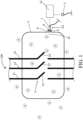
- Figure 1 illustrates schematically an electrical equipment 100 comprising a switchgear 2, a tank 1 configured for accommodating the switchgear 2, and an electronic control unit 15.
- the electronic control unit 15 is configured for implementing a gas temperature correction method that will be described below.
- the electronic control unit 15 is also configured for implementing a gas leakage detection method that will be later described.
- the tank 1 defines an enclosure configured to accommodate the switchgear 2. This inside volume of the tank 1 is filled with a gas G when the tank 1 is in normal operating conditions. The pressurized gas avoids the creation of an electric arc when the switchgear 2 is operated to interrupt the electrical current in the circuit.
- the outside of the tank 1 is exposed to the ambient temperature and ambient pressure of the ambient air A of the room in which the tank 1 is installed. The pressure of the gas is higher than the ambient pressure outside of the tank 1, which is the local atmospheric pressure.
- the tank 1 comprises several panels assembled to form a sealed enclosure defining a sealed volume. For example, the panels of the tank 1 are welded together. The panels may be fixed on a subframe that ensures a stiffness sufficient to resist to the pressure differential between the inside and the outside of the tank 1.
- the tank 1 comprises sealed interfaces allowing the entry and exit of the electrical conductors 11, 12, 13 connected to the switchgear 2.
- Each of the electrical conductor correspond here to a different phase of an electrical network.
- the tank 1 may be filled with inert gas like sulfur hexafluoride (SF 6 ).
- the tank 1 may also be filled by air.
- Each phase of the electrical circuit can be interrupted by an interrupter 21, 22, 23.
- Figure 1 represents the switchgear 2 in an opened position of the interrupters 21, 22, 23.
- the tank is built to be fluid tight, small leakages may occur during the lifetime of the electrical equipment 100 and the quantity of gas contained within the tank 1 may be slowly deplenished. The dielectric properties thus slowly deteriorate and the risks of creation of an electric arc increase. For this reason, the quantity of the gas contained in the tank 1 is monitored so that the users of the electrical equipment can receive an alert signal if the gas quantity becomes insufficient. In order to monitor gas quantity, gas temperature and gas pressure are measured.
- the electrical equipment 100 thus comprises a gas temperature sensor 3.
- the electrical equipment 100 also comprises a gas pressure sensor 4.
- the electrical equipment 100 additionally comprises an ambient temperature sensor 5.
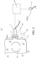
- the gas temperature sensor 3 comprises a temperature sensing element 6 configured to be in contact with the gas G inside the tank 1 and a sensor body 7 configured to be in contact with the ambient air A outside the tank 1.
- the gas temperature sensor 3 is here fixed to a panel of the tank 1.
- the panel of the tank 1 comprises an interface plug 9 on which the gas temperature sensor 3 is fixed.
- the interface plug 9 may comprise an internal thread in which the sensor body 7 is fixed like a screw.
- the interface plug 9 defines an opening 10 in a panel of the tank 1. This opening 10 is obtured by the body 7 of the gas temperature sensor 3 when the gas temperature sensor 3 is fitted. A seal may be disposed between the interface plug 9 and the body 7 of the temperature sensor to ensure fluid tightness of the tank 1.
- the body 7 of the gas temperature sensor 3 protrudes from an external side of a panel of the tank 1.
- the implementation of the sensor is easy, since it is disposed outside the tank 1, and the wires of the gas temperature sensor 3 are kept outside the internal volume of the tank.
- the body 7 of the gas temperature sensor 3 is exposed to the atmospheric pressure of the room.
- the gas pressure sensor 4 comprises a pressure sensing element 8 configured to be in contact with the gas contained in the tank 1.
- the pressure sensing element 8 and the temperature sensing element 6 are housed in the same sensor body 7.
- a single interface plug 9 is required to install two different sensors and obtain gas temperature measurement and gas pressure measurement.
- the sensor is here a multifunction sensor combining pressure measurement and temperature measurement.
- the gas pressure sensor 4 may be a dedicated sensor, separated and independent from the gas temperature sensor 3.
- the pressure sensor 4 is fixed to a specific interface plug defining another opening hole in a panel of the tank 1.
- the temperature sensing element 6 of the gas temperature sensor 3 may comprise a thermistor, for instance a negative coefficient thermistor.
- the temperature sensing element 6 may also comprise a thermocouple.
- the ambient temperature sensor 5 may comprise a thermistor, like a negative coefficient thermistor, or may comprise a thermocouple.
- the ambient temperature sensor 5 is for example installed on a control panel of the switchgear 2.
- the ambient temperature sensor 5 and the external surface of the tank 1 can be spaced apart from each other.
- the distance between the ambient temperature sensor 5 and the external surface of the tank 1 is preferably larger than 30 centimeters.
- the ambient temperature measurement is thus not affected by the heat dissipated by the tank 1.
- the measurement of the ambient temperature sensor 5 is considered to be fully representative of the ambient temperature of the room in which the tank 1 is installed.
- the ambient temperature sensor 5 comprises a temperature sensing element in contact with the ambient air A.
- the ambient temperature sensor 5 may comprise a thermistor, like for example a negative coefficient thermistor.
- the ambient temperature sensor 5 may comprise a thermocouple.
- the proposed method is for determining a quantity n of a gas G contained in a tank 1 of a gas insulated switchgear 2, the tank 1 comprising a gas temperature sensor 3 and a gas pressure sensor 4.
- the method comprises the following steps during a calibration phase:
- Gas temperature directly affects its quantity.
- the temperature measurement provided by the gas temperature sensor 3 may be significantly different from the actual temperature of the gas in close proximity to the switchgear 2, because the gas temperature sensor 3 is not located inside the tank and is not perfectly thermally isolated.
- the actual position of the gas temperature sensor 3 relatively to the tank 1 influences the thermal transfer and in turn the measurements of the gas temperature sensor 3.
- the measurement may be different whether the sensor is fitted at the top of the tank 1 or at the bottom.
- the proposed method integrates a model of the heat transfer towards the measurement sensor, in order to estimate the actual gas temperature with a better accuracy.
- the proposed thermal exchanges model uses only data obtained at two different instants without fitting any additional sensor inside the tank.
- the model can be individually calibrated on each individual equipment without any deviation from the configuration that will be used throughout the equipment life.
- the calibration is thus easy and with no risk for the equipment reliability.
- the method involves an initial calibration phase to identify the model parameters. Once the model parameters are identified they can be used for the measurement phase.
- the first pressure measurement P1 can be an average value of several consecutive samples.
- the second pressure measurement P2 can be an average value of several consecutive samples. Measurement noise is thus reduced.
- the steady-state model M comprises the ratio of:
- the temperature sensing element 6 of the gas temperature sensor 3 measures the temperature of the gas surrounding the sensing element 6.
- the first thermal resistance R1 is the thermal resistance between the gas G contained in the tank 1 and the gas in the temperature sensor 3.
- arrows referenced by signs f1, f2, f3 indicate the main contributors to thermal exchanges.
- f1 is a schematic representation of the natural convection inside the tank.
- f2 represents the heat flux between the walls of the tank 1 and the ambient air.
- f3 represents the heat flux between the ambient air and the gas temperature sensor 3, particularly the heat flux between the ambient air and the body 7 of the gas temperature sensor 3.
- Thermal exchanges and heat transfer are equivalent wordings.
- n K ⁇ Psens Tcor wherein K is a constant.
- K V R wherein R is the ideal gas constant and V is the internal volume of the tank 1.
- Gas quantity n determination is here based on ideal gas model. Different models could also be used without changing the general principal of the proposed methods. For instance, real gases model could also be used. Coefficient K is determined according to the model selected for the gas quantity determination.
- gas quantity can also be determined by other - parameters, such as gas density D or equivalent gas pressure P0.
- T0 is for example 293K.
- the gas quantity according to the present disclosure can correspond to any parameter that is proportional to a fraction between the acquired gas pressure measured by the gas pressure sensor and the determined corrected temperature, which provides a true reflection of the quantity of gas contained in the tank.
- the step (iii) of determining a steady-state model M of the tank thermal exchanges comprises the sub-steps :
- This model with two different thermal resistance provides a good accuracy and requires only reasonable effort for its calibration. Furthermore, this model is robust and can be used for various equipment configurations.
- the step (iii) of determining a steady-state model M of the tank 1 thermal exchanges comprises the sub-step: (iii3) after the acquisition of the first temperature T1 and before the acquisition of the second temperature measurement T2, modifying an electrical current intensity in the switchgear 2 so that the temperature of the gas contained in the tank 1 is modified.
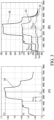
- Figure 3 represents the evolution versus time of the pressure and temperature of the gas contained in the tank 1, over a duration of about two hours (7000 seconds).
- Part A of figure 3 is the evolution of the measured pressure, represented by curve 34.
- Part B of figure 3 is the evolution of ambient temperature Tamb represented by curve 35, measured gas temperature Tsens represented by curve 33, and real gas temperature represented by curve 38.
- the real gas temperature is here measured by an experimental set-up specifically added for experimental studies, in which a temperature sensor is installed in immediate proximity to the switchgear contacts. This set-up is not implemented on production equipment, and the proposed method will not rely on this experimental set-up.
- Real gas temperature is represented on curve 38 for information only.
- current intensity is comprised between 1000 A and 1200 A when the first measurement of pressure P1 and temperature T1 is performed at instant t 1 . Then, current intensity is increased to a value comprised between 1600 A and 2000 A. This higher intensity dissipates more heat inside the tank 1 and the gas progressively warms-up until new steady state conditions are obtained.
- the second measurement of pressure P2 and temperature T2, at instant t2, corresponds to these new steady state conditions. No fan is present inside the tank 1. No forced convection is involved in the heat transfer inside the tank 1.
- the first instant t 1 and the second instant t 2 are selected such that the difference between the second instant t 2 and the first instant t 1 is higher than a first predetermined threshold Th1.
- the first predetermined threshold Th1 is for example 3 hours.
- the duration between t 1 and t 2 for instance satisfies the condition: (t 2 - t 1 ) > 3 hours. Other minimum durations between t 1 and t 2 are possible.
- the duration between t 1 and t 2 is selected to be long enough so that a new thermal equilibrium is obtained when the second temperature measurement T2 and the second pressure measurement P2 are performed.
- first instant t 1 and the second instant t 2 are selected such that: the difference between the second acquired temperature T2 and the first acquired temperature T1 is higher than a second predetermined threshold Th2.
- the second predetermined threshold Th2 is for example 5°C.
- the temperature T2 which corresponds to instant t 2 satisfies for instance the condition: T2 - T1 > 5°C.
- This temperature difference indicates that the transition between the first state and the second state has enough amplitude to be differentiated from the background noise of a steady state operation.
- Figure 3 represents a situation in which temperature is increased between instant t 1 and instant t 2 . Transitions in which temperature decreases between instant t 1 and instant t 2 can equally be used for the calibration phase of the model.
- the first instant t 1 and the second instant t 2 are also selected such that: the difference between the second acquired temperature T2 and the second ambient temperature Tamb2 is higher than a third predetermined threshold Th3.
- the third predetermined threshold Th3 is for instance 5°C.
- the temperature T2 which corresponds to instant t 2 also satisfies the condition: (T2 - Tamb2) > 5°C. As before, this temperature difference indicates that the transition between the first state and the second state has enough amplitude for allowing an accurate identification of the model parameters.
- the sub-steps (iii1), (iii2) and (iii3) are iterated for determining the steady-state model M of the tank thermal exchanges. For this, successive current steps may be performed. The consistency of the identification of the model parameters can thus be checked.
- the ratio R1/R2 is initialized for instance to 1,25. This baseline value of the ratio R1/R2 is then updated according to the calculation of equation 5 when the conditions to calculate this ratio are met.
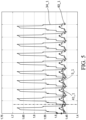
- Figure 4 illustrates the results of the measurement phase of the method.
- curve 40 indicates the evolution of the determined equivalent pressure P0 and curve 34 indicate the gas pressure Psens measured by the gas pressure sensor 4.
- Curve 39 is, for comparison, a calculation of equivalent gas pressure performed from the raw measurement of pressure Psens and the raw measured temperature Tsens, in other words without modelling the tank heat transfers.
- Instants t 3 and t 4 are instants at which operating conditions are modified and tank pressure increases, which reflects on the curve evolution. The evolution is represented over a two-hour time window, 0 to 8000 seconds.
- Instant t 5 and t 6 are instants at which operating conditions are modified and the internal pressure of the tank 1 decreases.
- the modelling of the thermal transfer affecting the gas temperature measurement it can be observed than the fluctuations of curve 40 are much smaller than the fluctuations of curve 39.
- the modelling of the tank heat transfer affecting the gas temperature measurement improves the accuracy of the pressure (and thus gas quantity) determination.
- the present disclosure relates also to a method for detecting a gas leakage in a tank 1 of a gas insulated switchgear 2, comprising the steps:
- Tank leakage detection methods are generally based on a monitoring of the pressure inside the tank. As this pressure is influenced by the temperature of the gas, an observed drop in pressure is not necessarily caused by a leakage but can also be caused by a temperature drop. Similarly, the effect of a real leakage may remain undetected if the gas temperature increases simultaneously and tends to maintain the existing pressure. Using a gas quantity as monitored parameter increases the accuracy of the leakage detection method. The fault detection may be quicker, as the safety margin integrated to avoid false detections can be reduced.
- the sampling frequency of the gas pressure measurement may be comprised between 0,01 Hz and 1 Hz.
- the ratio R1/R2 is kept constant when the gas leakage detection method is activated.
- the method comprises the step:
- Using a filtered value helps putting into evidence the long-term evolution of the quantity of the gas contained inside the tank, independently from the short-term fluctuations caused by the changes in operating conditions, like current intensity.
- the filtered value Nfilt of the gas quantity n is a sliding average of the gas quantity n over a predetermined duration T.
- the predetermined duration T is higher than 10 days, or even higher than 20 days.
- the filtered value Nfilt of the gas quantity n is obtained by a first order filter applied to the gas quantity D.
- the time constant of the first order filter is for example comprised between 1 hour and 6 hours. Other filtering methods are of course possible.
- the method comprises the steps:
- a warning signal can be emitted.
- the users of the electrical equipment can thus take corrective actions in response to the warning signal.
- the warning signal can be a warning indicator lighting on.
- the warning signal can be a sound indicator.
- the warning signal can be a fault code stored in a permanent memory of the electronic control unit on which the method is implemented.
- the severity of the identified fault can be quantified.
- the context associated with the detected fault like current intensity, date and time, ambient temperature, and any other parameters, can be stored in memory for subsequent analysis of the identified fault.
- Figure 5 illustrates the different parameters of the leakage detection method in a situation where the tank is sealed, i.e no leakage is present.
- Figure 6 illustrates the same parameters when a leakage is actually present. Horizontal axis is elapsed time t. The displayed time window is 40 days.
- gas quantity n and corresponding filtered value Nfilt are more particularly determined through the equivalent gas pressure P0 and corresponding filtered value Pfilt.
- curve 40_1 is the temporal evolution of equivalent pressure P0 determined by the proposed method.
- Curve 41_1 is the temporal evolution of the filtered pressure Pfilt.
- Parameter S_1 represents the slope of the filtered quantity 41_1.
- Curve 34_1 represents, for comparison, the temporal evolution of the measured pressure Psens, with the same scale as quantity.
- the different curves are referenced by the same main number associated with the index "_2".
- curve 40_1 of determined gas equivalent pressure shows oscillations due to the periodic evolution of the current intensity in the switchgear 2.
- Curve 41_1 is the filtered value of determined pressure. This filtered value is almost constant, and its slope S_1 is almost null. The slope can be determined by linear regression of the curve 41_1. This temporal evolution shows that there' s no leakage during the represented time window.
- curve 34_1 shows that the measured pressure Psens is affected by much larger fluctuations that the determined quantity.
- curve 40_2 of determined equivalent pressure still shows oscillations due to the periodic evolution of the current intensity, associated with a slow long-term decrease.
- the filtered value 41_2 of gas pressure has a quasi-linear evolution with a negative slope S_2. This slope is here lower than the threshold Smax, represented as dashed line. This indicates that the gas equivalent pressure (and thus gas quantity) decreases more quickly than the acceptable reference. A leakage is thus detected.
- Curve 34_2 illustrates the variations of measured pressure Psens versus time. For comparison, the pressure variations in absence of leakage, represented by curve 34_1, are superposed on the same graph. The amplitude of the periodic variations of pressure are much larger than the slow long-term drift, making leakage detection more difficult. The proposed method is able to confirm a leakage earlier and more accurately.
Landscapes
- Physics & Mathematics (AREA)
- General Physics & Mathematics (AREA)
- Gas-Insulated Switchgears (AREA)
Claims (15)
- Procédé de détermination d'une quantité (n) d'un gaz (G) contenu dans une cuve (1) d'un appareillage de commutation (2) à isolation gazeuse, la cuve (1) comprenant un capteur de température de gaz (3) et un capteur de pression de gaz (4), le procédé comprenant les étapes suivantes lors d'une phase de mesure :(iv) l'acquisition d'une température de gaz (Tsens) mesurée par le capteur de température de gaz (3),(v) l'acquisition d'une pression de gaz (Psens) mesurée par le capteur de pression de gaz (4),(vi) l'acquisition d'une température ambiante (Tamb) mesurée par un capteur de température ambiante (5) à l'extérieur de la cuve (1) pendant la phase de mesure,caractérisé en ce que le procédé comprend en outre les étapes suivantes lors d'une phase d'étalonnage :(i) l'acquisition d'une première température (T1) et d'une seconde température (T2) mesurées par le capteur de température de gaz (3) respectivement à un premier instant (t1) et à un second instant (t2),(ii) l'acquisition d'une première pression (P1) et d'une seconde pression (P2) mesurées par le capteur de pression de gaz (4) au premier instant (t1) et au second instant (t2),(iii) la détermination d'un modèle de régime permanent (M) des échanges thermiques de la cuve à partir des première et seconde températures (T1, T2) acquises et des première et seconde pressions (P1, P2) acquises ;et comprenant en outre l'étape suivante lors de la phase de mesure :
(vii) la détermination de la quantité (n) à partir de la température de gaz (Tsens) acquise, de la pression de gaz (Psens) acquise, de la température ambiante (Tamb) acquise et du modèle de régime permanent (M) déterminé. - Procédé selon la revendication 2, dans lequel le modèle de régime permanent (M) comprend le rapport :- d'une première résistance thermique (R1) entre le gaz (G) contenu dans la cuve (1) et le capteur de température de gaz (3), et- d'une seconde résistance thermique (R2) entre le capteur de température de gaz (3) et l'air ambiant (A) à l'extérieur de la cuve (1).
- Procédé selon la revendication 1 ou 2, dans lequel la quantité (n) de gaz est déterminée à partir du rapport de la pression de gaz (Psens) acquise et d'une température de gaz corrigée (Tcor), la température de gaz corrigée (Tcor) étant calculée à partir de l'équation :
 Tcor est la température corrigée (Tcor) du gaz à l'intérieur de la cuve (1),Tsens est la température de gaz (Tsens) mesurée par le capteur de température de gaz (3),R1 est la première résistance thermique (R1) entre le gaz (G) contenu dans la cuve (1) et le capteur de température de gaz (3),R2 est la seconde résistance thermique (R2) entre le capteur de température de gaz (3) et l'air ambiant (A) à l'extérieur de la cuve (1),Tamb est la température ambiante (Tamb) mesurée à l'extérieur de la cuve (1).
 - Procédé selon l'une quelconque des revendications précédentes, dans lequel l'étape (iii) de détermination d'un modèle de régime permanent (M) des échanges thermiques de la cuve comprend les sous-étapes suivantes :(iii1) l'acquisition d'une première température ambiante (Tamb1) et d'une seconde température ambiante (Tamb2), respectivement au premier instant (t1) et au second instant (t2) pendant la phase d'étalonnage,(iii2) le calcul d'une valeur actualisée du rapport de la première résistance thermique (R1) entre le gaz (G) contenu dans la cuve (1) et le capteur de température de gaz (3) et de la seconde résistance thermique (R2) entre le capteur de température de gaz (3) et l'air ambiant (A) à l'extérieur de la cuve (1), à partir de l'équation :
 R1 est la première résistance thermique (R1) entre le gaz (G) contenu dans la cuve (1) et le capteur de température de gaz (3),R2 est la seconde résistance thermique (R2) entre le capteur de température de gaz (3) et l'air ambiant (A) à l'extérieur de la cuve (1),P1 est la pression (P1) mesurée par le capteur de pression de gaz (4) au premier instant (t1),P2 est la pression (P2) mesurée par le capteur de pression de gaz (4) au second instant (t2),T1 est la première température (T1) mesurée par le capteur de température de gaz (3) au premier instant (t1),T2 est la seconde température (T2) mesurée par le capteur de température de gaz (3) au second instant (t2),Tamb1 est la température ambiante (Tamb1) au premier instant (t1),Tamb2 est la température ambiante (Tamb2) au second instant (t2).
 - Procédé selon l'une des revendications précédentes, dans lequel l'étape (iii) de détermination d'un modèle de régime permanent (M) des échanges thermiques de la cuve (1) comprend la sous-étape suivante :
(iii3) après l'acquisition de la première température (T1) et avant l'acquisition de la seconde mesure de température (T2), la modification d'une intensité de courant électrique dans l'appareillage de commutation (2) de sorte que la température du gaz contenu dans la cuve (1) est modifiée. - Procédé selon l'une quelconque des revendications précédentes, dans lequel le premier instant (t1) et le second instant (t2) sont sélectionnés de telle sorte que :
la différence entre le second instant (t2) et le premier instant (t1) est supérieure à un premier seuil prédéterminé. - Procédé selon l'une quelconque des revendications précédentes, dans lequel le premier instant (t1) et le second instant (t2) sont sélectionnés de telle sorte que :
la différence entre la seconde température (T2) acquise et la première température (T1) acquise est supérieure à un deuxième seuil prédéterminé. - Procédé selon l'une quelconque des revendications précédentes en combinaison avec la revendication 4, dans lequel le premier instant (t1) et le second instant (t2) sont sélectionnés de telle sorte que :
la différence entre la seconde température (T2) acquise et la seconde température ambiante (Tamb2) est supérieure à un troisième seuil prédéterminé. - Procédé selon l'une quelconque des revendications précédentes en combinaison avec la revendication 4, dans lequel les sous-étapes (iii1), (iii2) et (iii3) sont itérées pour déterminer le modèle de régime permanent (M) des échanges thermiques de la cuve.
- Procédé de détection d'une fuite de gaz dans une cuve (1) d'un appareillage de commutation (2) à isolation gazeuse, comprenant les étapes suivantes :- la détermination de la quantité (n) du gaz (G) contenu dans la cuve (1) par le procédé selon l'une des revendications précédentes,- la détection d'une fuite de gaz sur la base de l'évolution de la quantité (n) de gaz en fonction du temps.
- Procédé selon la revendication 10, comprenant les étapes suivantes :- la détermination d'une valeur filtrée (Nfilt) de la quantité (n) de gaz en fonction du temps,- la détection d'une fuite de gaz sur la base de l'évolution de la valeur filtrée (Nfilt) de la quantité (n) de gaz en fonction du temps.
- Procédé selon la revendication précédente, comprenant les étapes suivantes :- le calcul d'une pente moyenne (S) de la valeur filtrée (Nfilt) de la quantité (n) de gaz,- si la pente moyenne (S) est supérieure à un seuil prédéterminé (Smax), la détection qu'une fuite est présente,- si la pente moyenne (S) est inférieure ou égale au seuil prédéterminé (Smax), la détection que la cuve (1) est étanche.
- Procédé selon la revendication 11 ou 12, dans lequel la valeur filtrée (Nfilt) de la quantité (n) de gaz est une moyenne mobile de la quantité (n) de gaz sur une durée (n) prédéterminée.
- Procédé selon la revendication 11 ou 12, dans lequel la valeur filtrée (Nfilt) de la quantité (n) de gaz est obtenue par un filtre de premier ordre appliqué à la quantité (n) de gaz.
- Équipement électrique (100) comprenant un appareillage de commutation (2), une cuve (1) configurée pour loger l'appareillage de commutation (2), et une unité électronique de commande (15),
caractérisé en ce que :
l'unité de commande (15) est configurée pour mettre en oeuvre un procédé de détermination de quantité de gaz selon l'une des revendications 1 à 9 ou pour mettre en oeuvre un procédé de détection de fuite de gaz selon l'une des revendications 10 à 14.
Priority Applications (3)
| Application Number | Priority Date | Filing Date | Title |
|---|---|---|---|
| EP22305632.6A EP4269976B1 (fr) | 2022-04-28 | 2022-04-28 | Procédé pour déterminer une quantité de gaz dans un appareillage de commutation isolé |
| US18/135,776 US12546678B2 (en) | 2022-04-28 | 2023-04-18 | Method for determining a gas quantity in an insulated switchgear |
| CN202310465117.6A CN116973054A (zh) | 2022-04-28 | 2023-04-26 | 用于确定绝缘开关设备中的气体的量的方法 |
Applications Claiming Priority (1)
| Application Number | Priority Date | Filing Date | Title |
|---|---|---|---|
| EP22305632.6A EP4269976B1 (fr) | 2022-04-28 | 2022-04-28 | Procédé pour déterminer une quantité de gaz dans un appareillage de commutation isolé |
Publications (3)
| Publication Number | Publication Date |
|---|---|
| EP4269976A1 EP4269976A1 (fr) | 2023-11-01 |
| EP4269976B1 true EP4269976B1 (fr) | 2024-12-25 |
| EP4269976C0 EP4269976C0 (fr) | 2024-12-25 |
Family
ID=81654944
Family Applications (1)
| Application Number | Title | Priority Date | Filing Date |
|---|---|---|---|
| EP22305632.6A Active EP4269976B1 (fr) | 2022-04-28 | 2022-04-28 | Procédé pour déterminer une quantité de gaz dans un appareillage de commutation isolé |
Country Status (3)
| Country | Link |
|---|---|
| US (1) | US12546678B2 (fr) |
| EP (1) | EP4269976B1 (fr) |
| CN (1) | CN116973054A (fr) |
Families Citing this family (2)
| Publication number | Priority date | Publication date | Assignee | Title |
|---|---|---|---|---|
| CN117629414B (zh) * | 2024-01-25 | 2024-05-03 | 国网辽宁省电力有限公司电力科学研究院 | 一种混合气体绝缘变电站的母线温度检测装置及方法 |
| CN120404001B (zh) * | 2025-05-16 | 2026-04-17 | 靖江市亚泰特种材料制造有限公司 | 一种用于高原环境下的方舱气密性检测方法 |
Family Cites Families (9)
| Publication number | Priority date | Publication date | Assignee | Title |
|---|---|---|---|---|
| JP2011130581A (ja) * | 2009-12-17 | 2011-06-30 | Mitsubishi Electric Corp | ガス圧監視装置ならびにガス絶縁電気機器 |
| WO2013087683A1 (fr) * | 2011-12-13 | 2013-06-20 | Abb Technology Ag | Procédé de fonctionnement d'un appareil électrique |
| FR3001345B1 (fr) * | 2013-01-22 | 2016-01-22 | Alstom Technology Ltd | Determination d'un taux de fuite d'un gaz d'isolation |
| US9696248B2 (en) * | 2014-04-29 | 2017-07-04 | Solon Manufacturing Company | Gas insulated switchgear monitoring apparatus and method |
| WO2016115388A1 (fr) * | 2015-01-15 | 2016-07-21 | Solon Manufacturing Company | Appareil de mesure de gaz |
| GB2552447B (en) * | 2016-04-06 | 2019-06-12 | Qhi Group Ltd | Fault monitoring systems and methods for detecting connectivity faults |
| EP3621096A1 (fr) * | 2018-09-07 | 2020-03-11 | Siemens Aktiengesellschaft | Système de surveillance de gaz pour appareils de commutation à isolation gazeuse |
| EP3671997B1 (fr) * | 2018-12-20 | 2025-04-09 | ABB Schweiz AG | Système de surveillance d'un appareillage de commutation |
| EP4145650B1 (fr) * | 2021-09-07 | 2024-10-09 | Eaton Intelligent Power Limited | Prédiction de la durée de vie de remplissage au gaz d'un appareillage électrique |
-
2022
- 2022-04-28 EP EP22305632.6A patent/EP4269976B1/fr active Active
-
2023
- 2023-04-18 US US18/135,776 patent/US12546678B2/en active Active
- 2023-04-26 CN CN202310465117.6A patent/CN116973054A/zh active Pending
Also Published As
| Publication number | Publication date |
|---|---|
| EP4269976C0 (fr) | 2024-12-25 |
| EP4269976A1 (fr) | 2023-11-01 |
| CN116973054A (zh) | 2023-10-31 |
| US20230349787A1 (en) | 2023-11-02 |
| US12546678B2 (en) | 2026-02-10 |
Similar Documents
| Publication | Publication Date | Title |
|---|---|---|
| EP2519957B1 (fr) | Système pour surveiller le niveau d'huile et détecter des fuites dans des transformateurs de puissance, réacteurs, transformateurs de courant et de tension, traversées haute tension et analogue | |
| US12546678B2 (en) | Method for determining a gas quantity in an insulated switchgear | |
| TW484087B (en) | Intelligent analysis system and method for fluid-filled electrical equipment | |
| US20150355049A1 (en) | Determination of a leakage rate of an insulation gas | |
| JP6514598B2 (ja) | ガスリーク検知装置およびガスリーク検知方法 | |
| CN112655063B (zh) | 用于气体绝缘开关设备的气体监测系统 | |
| US20150308938A1 (en) | Gas insulated switchgear monitoring apparatus and method | |
| JP2011130581A (ja) | ガス圧監視装置ならびにガス絶縁電気機器 | |
| EP2113929A1 (fr) | Procédé et dispositif pour déterminer l'humidité relative d'un appareil électrique isolé rempli de liquide | |
| KR20110108550A (ko) | 가스절연 송전선의 누기 측정장치 | |
| JP2016057135A (ja) | ガスリーク検知装置およびガスリーク検査方法 | |
| EP4145650B1 (fr) | Prédiction de la durée de vie de remplissage au gaz d'un appareillage électrique | |
| JPH05283240A (ja) | 油入変圧器 | |
| JP2014142996A (ja) | 密閉型開閉装置の真空度劣化検出装置 | |
| US20240377238A1 (en) | Method for determining a quantity of gas contained in an insulated switchgear | |
| JP5233728B2 (ja) | ガス圧監視装置ならびにガス絶縁電気機器 | |
| KR20150048286A (ko) | 가스절연개폐장치 가스 저압경보 시험방법 및 장치 | |
| CN114325180B (zh) | 一种基于六氟化硫表计压力监测的电力设备发热诊断方法 | |
| JPH07129870A (ja) | ガス絶縁開閉装置のガス漏れ検出装置 | |
| JP6207805B1 (ja) | 真空バルブの真空劣化監視装置及びこれを備えた開閉装置 | |
| CN114729960A (zh) | 具有集成传感器的智能电气套管 | |
| JPH07287040A (ja) | ガス絶縁変圧器の監視装置 | |
| CN104137358A (zh) | 对气体绝缘隔室进行监视的方法和装置 | |
| KR102808541B1 (ko) | 육불화황 가스 배관 관통형 가스 상태 감지 장치 및 방법 | |
| EP4675288A1 (fr) | Procédé et appareil de vérification de simulation pour relais de densité de gaz |
Legal Events
| Date | Code | Title | Description |
|---|---|---|---|
| PUAI | Public reference made under article 153(3) epc to a published international application that has entered the european phase |
Free format text: ORIGINAL CODE: 0009012 |
|
| STAA | Information on the status of an ep patent application or granted ep patent |
Free format text: STATUS: THE APPLICATION HAS BEEN PUBLISHED |
|
| AK | Designated contracting states |
Kind code of ref document: A1 Designated state(s): AL AT BE BG CH CY CZ DE DK EE ES FI FR GB GR HR HU IE IS IT LI LT LU LV MC MK MT NL NO PL PT RO RS SE SI SK SM TR |
|
| STAA | Information on the status of an ep patent application or granted ep patent |
Free format text: STATUS: REQUEST FOR EXAMINATION WAS MADE |
|
| 17P | Request for examination filed |
Effective date: 20240417 |
|
| RBV | Designated contracting states (corrected) |
Designated state(s): AL AT BE BG CH CY CZ DE DK EE ES FI FR GB GR HR HU IE IS IT LI LT LU LV MC MK MT NL NO PL PT RO RS SE SI SK SM TR |
|
| GRAP | Despatch of communication of intention to grant a patent |
Free format text: ORIGINAL CODE: EPIDOSNIGR1 |
|
| STAA | Information on the status of an ep patent application or granted ep patent |
Free format text: STATUS: GRANT OF PATENT IS INTENDED |
|
| RIC1 | Information provided on ipc code assigned before grant |
Ipc: H01H 33/56 20060101ALI20240815BHEP Ipc: G01N 9/26 20060101ALI20240815BHEP Ipc: G01L 27/00 20060101ALI20240815BHEP Ipc: G01M 3/32 20060101AFI20240815BHEP |
|
| GRAJ | Information related to disapproval of communication of intention to grant by the applicant or resumption of examination proceedings by the epo deleted |
Free format text: ORIGINAL CODE: EPIDOSDIGR1 |
|
| STAA | Information on the status of an ep patent application or granted ep patent |
Free format text: STATUS: REQUEST FOR EXAMINATION WAS MADE |
|
| INTG | Intention to grant announced |
Effective date: 20240917 |
|
| RAP3 | Party data changed (applicant data changed or rights of an application transferred) |
Owner name: SCHNEIDER ELECTRIC INDUSTRIES SAS |
|
| GRAP | Despatch of communication of intention to grant a patent |
Free format text: ORIGINAL CODE: EPIDOSNIGR1 |
|
| STAA | Information on the status of an ep patent application or granted ep patent |
Free format text: STATUS: GRANT OF PATENT IS INTENDED |
|
| GRAS | Grant fee paid |
Free format text: ORIGINAL CODE: EPIDOSNIGR3 |
|
| INTC | Intention to grant announced (deleted) | ||
| GRAA | (expected) grant |
Free format text: ORIGINAL CODE: 0009210 |
|
| STAA | Information on the status of an ep patent application or granted ep patent |
Free format text: STATUS: THE PATENT HAS BEEN GRANTED |
|
| INTG | Intention to grant announced |
Effective date: 20241030 |
|
| AK | Designated contracting states |
Kind code of ref document: B1 Designated state(s): AL AT BE BG CH CY CZ DE DK EE ES FI FR GB GR HR HU IE IS IT LI LT LU LV MC MK MT NL NO PL PT RO RS SE SI SK SM TR |
|
| REG | Reference to a national code |
Ref country code: GB Ref legal event code: FG4D |
|
| REG | Reference to a national code |
Ref country code: CH Ref legal event code: EP |
|
| REG | Reference to a national code |
Ref country code: DE Ref legal event code: R096 Ref document number: 602022009085 Country of ref document: DE |
|
| REG | Reference to a national code |
Ref country code: IE Ref legal event code: FG4D |
|
| U01 | Request for unitary effect filed |
Effective date: 20241225 |
|
| U07 | Unitary effect registered |
Designated state(s): AT BE BG DE DK EE FI FR IT LT LU LV MT NL PT RO SE SI Effective date: 20250113 |
|
| PG25 | Lapsed in a contracting state [announced via postgrant information from national office to epo] |
Ref country code: HR Free format text: LAPSE BECAUSE OF FAILURE TO SUBMIT A TRANSLATION OF THE DESCRIPTION OR TO PAY THE FEE WITHIN THE PRESCRIBED TIME-LIMIT Effective date: 20241225 |
|
| PG25 | Lapsed in a contracting state [announced via postgrant information from national office to epo] |
Ref country code: NO Free format text: LAPSE BECAUSE OF FAILURE TO SUBMIT A TRANSLATION OF THE DESCRIPTION OR TO PAY THE FEE WITHIN THE PRESCRIBED TIME-LIMIT Effective date: 20250325 |
|
| PG25 | Lapsed in a contracting state [announced via postgrant information from national office to epo] |
Ref country code: GR Free format text: LAPSE BECAUSE OF FAILURE TO SUBMIT A TRANSLATION OF THE DESCRIPTION OR TO PAY THE FEE WITHIN THE PRESCRIBED TIME-LIMIT Effective date: 20250326 |
|
| PG25 | Lapsed in a contracting state [announced via postgrant information from national office to epo] |
Ref country code: RS Free format text: LAPSE BECAUSE OF FAILURE TO SUBMIT A TRANSLATION OF THE DESCRIPTION OR TO PAY THE FEE WITHIN THE PRESCRIBED TIME-LIMIT Effective date: 20250325 |
|
| U20 | Renewal fee for the european patent with unitary effect paid |
Year of fee payment: 4 Effective date: 20250424 |
|
| PG25 | Lapsed in a contracting state [announced via postgrant information from national office to epo] |
Ref country code: SM Free format text: LAPSE BECAUSE OF FAILURE TO SUBMIT A TRANSLATION OF THE DESCRIPTION OR TO PAY THE FEE WITHIN THE PRESCRIBED TIME-LIMIT Effective date: 20241225 |
|
| PG25 | Lapsed in a contracting state [announced via postgrant information from national office to epo] |
Ref country code: PL Free format text: LAPSE BECAUSE OF FAILURE TO SUBMIT A TRANSLATION OF THE DESCRIPTION OR TO PAY THE FEE WITHIN THE PRESCRIBED TIME-LIMIT Effective date: 20241225 |
|
| PG25 | Lapsed in a contracting state [announced via postgrant information from national office to epo] |
Ref country code: ES Free format text: LAPSE BECAUSE OF FAILURE TO SUBMIT A TRANSLATION OF THE DESCRIPTION OR TO PAY THE FEE WITHIN THE PRESCRIBED TIME-LIMIT Effective date: 20241225 |
|
| PG25 | Lapsed in a contracting state [announced via postgrant information from national office to epo] |
Ref country code: IS Free format text: LAPSE BECAUSE OF FAILURE TO SUBMIT A TRANSLATION OF THE DESCRIPTION OR TO PAY THE FEE WITHIN THE PRESCRIBED TIME-LIMIT Effective date: 20250425 |
|
| PG25 | Lapsed in a contracting state [announced via postgrant information from national office to epo] |
Ref country code: SK Free format text: LAPSE BECAUSE OF FAILURE TO SUBMIT A TRANSLATION OF THE DESCRIPTION OR TO PAY THE FEE WITHIN THE PRESCRIBED TIME-LIMIT Effective date: 20241225 |
|
| PG25 | Lapsed in a contracting state [announced via postgrant information from national office to epo] |
Ref country code: CZ Free format text: LAPSE BECAUSE OF FAILURE TO SUBMIT A TRANSLATION OF THE DESCRIPTION OR TO PAY THE FEE WITHIN THE PRESCRIBED TIME-LIMIT Effective date: 20241225 |
|
| PLBE | No opposition filed within time limit |
Free format text: ORIGINAL CODE: 0009261 |
|
| STAA | Information on the status of an ep patent application or granted ep patent |
Free format text: STATUS: NO OPPOSITION FILED WITHIN TIME LIMIT |
|
| REG | Reference to a national code |
Ref country code: CH Ref legal event code: L10 Free format text: ST27 STATUS EVENT CODE: U-0-0-L10-L00 (AS PROVIDED BY THE NATIONAL OFFICE) Effective date: 20251105 |
|
| REG | Reference to a national code |
Ref country code: CH Ref legal event code: H13 Free format text: ST27 STATUS EVENT CODE: U-0-0-H10-H13 (AS PROVIDED BY THE NATIONAL OFFICE) Effective date: 20251125 |
|
| 26N | No opposition filed |
Effective date: 20250926 |
|
| PG25 | Lapsed in a contracting state [announced via postgrant information from national office to epo] |
Ref country code: MC Free format text: LAPSE BECAUSE OF FAILURE TO SUBMIT A TRANSLATION OF THE DESCRIPTION OR TO PAY THE FEE WITHIN THE PRESCRIBED TIME-LIMIT Effective date: 20241225 |
|
| PG25 | Lapsed in a contracting state [announced via postgrant information from national office to epo] |
Ref country code: CH Free format text: LAPSE BECAUSE OF NON-PAYMENT OF DUE FEES Effective date: 20250430 |
|
| PG25 | Lapsed in a contracting state [announced via postgrant information from national office to epo] |
Ref country code: IE Free format text: LAPSE BECAUSE OF NON-PAYMENT OF DUE FEES Effective date: 20250428 |