EP4269999B1 - Procédé et système de tomographie par ultrasons pour évaluer la corrosion d'une canalisation - Google Patents
Procédé et système de tomographie par ultrasons pour évaluer la corrosion d'une canalisation Download PDFInfo
- Publication number
- EP4269999B1 EP4269999B1 EP23169298.9A EP23169298A EP4269999B1 EP 4269999 B1 EP4269999 B1 EP 4269999B1 EP 23169298 A EP23169298 A EP 23169298A EP 4269999 B1 EP4269999 B1 EP 4269999B1
- Authority
- EP
- European Patent Office
- Prior art keywords
- pipe
- corrosion
- transducers
- measurement
- under examination
- Prior art date
- Legal status (The legal status is an assumption and is not a legal conclusion. Google has not performed a legal analysis and makes no representation as to the accuracy of the status listed.)
- Active
Links
Images


Classifications
-
- G—PHYSICS
- G01—MEASURING; TESTING
- G01N—INVESTIGATING OR ANALYSING MATERIALS BY DETERMINING THEIR CHEMICAL OR PHYSICAL PROPERTIES
- G01N29/00—Investigating or analysing materials by the use of ultrasonic, sonic or infrasonic waves; Visualisation of the interior of objects by transmitting ultrasonic or sonic waves through the object
- G01N29/04—Analysing solids
- G01N29/043—Analysing solids in the interior, e.g. by shear waves
-
- G—PHYSICS
- G01—MEASURING; TESTING
- G01N—INVESTIGATING OR ANALYSING MATERIALS BY DETERMINING THEIR CHEMICAL OR PHYSICAL PROPERTIES
- G01N29/00—Investigating or analysing materials by the use of ultrasonic, sonic or infrasonic waves; Visualisation of the interior of objects by transmitting ultrasonic or sonic waves through the object
- G01N29/04—Analysing solids
- G01N29/06—Visualisation of the interior, e.g. acoustic microscopy
- G01N29/0654—Imaging
- G01N29/0672—Imaging by acoustic tomography
-
- G—PHYSICS
- G01—MEASURING; TESTING
- G01N—INVESTIGATING OR ANALYSING MATERIALS BY DETERMINING THEIR CHEMICAL OR PHYSICAL PROPERTIES
- G01N29/00—Investigating or analysing materials by the use of ultrasonic, sonic or infrasonic waves; Visualisation of the interior of objects by transmitting ultrasonic or sonic waves through the object
- G01N29/44—Processing the detected response signal, e.g. electronic circuits specially adapted therefor
- G01N29/4409—Processing the detected response signal, e.g. electronic circuits specially adapted therefor by comparison
- G01N29/4418—Processing the detected response signal, e.g. electronic circuits specially adapted therefor by comparison with a model, e.g. best-fit, regression analysis
-
- G—PHYSICS
- G01—MEASURING; TESTING
- G01N—INVESTIGATING OR ANALYSING MATERIALS BY DETERMINING THEIR CHEMICAL OR PHYSICAL PROPERTIES
- G01N29/00—Investigating or analysing materials by the use of ultrasonic, sonic or infrasonic waves; Visualisation of the interior of objects by transmitting ultrasonic or sonic waves through the object
- G01N29/44—Processing the detected response signal, e.g. electronic circuits specially adapted therefor
- G01N29/4445—Classification of defects
-
- G—PHYSICS
- G01—MEASURING; TESTING
- G01N—INVESTIGATING OR ANALYSING MATERIALS BY DETERMINING THEIR CHEMICAL OR PHYSICAL PROPERTIES
- G01N29/00—Investigating or analysing materials by the use of ultrasonic, sonic or infrasonic waves; Visualisation of the interior of objects by transmitting ultrasonic or sonic waves through the object
- G01N29/44—Processing the detected response signal, e.g. electronic circuits specially adapted therefor
- G01N29/4481—Neural networks
-
- G—PHYSICS
- G01—MEASURING; TESTING
- G01N—INVESTIGATING OR ANALYSING MATERIALS BY DETERMINING THEIR CHEMICAL OR PHYSICAL PROPERTIES
- G01N2291/00—Indexing codes associated with group G01N29/00
- G01N2291/10—Number of transducers
- G01N2291/102—Number of transducers one emitter, one receiver
-
- G—PHYSICS
- G01—MEASURING; TESTING
- G01N—INVESTIGATING OR ANALYSING MATERIALS BY DETERMINING THEIR CHEMICAL OR PHYSICAL PROPERTIES
- G01N2291/00—Indexing codes associated with group G01N29/00
- G01N2291/10—Number of transducers
- G01N2291/106—Number of transducers one or more transducer arrays
-
- G—PHYSICS
- G01—MEASURING; TESTING
- G01N—INVESTIGATING OR ANALYSING MATERIALS BY DETERMINING THEIR CHEMICAL OR PHYSICAL PROPERTIES
- G01N2291/00—Indexing codes associated with group G01N29/00
- G01N2291/26—Scanned objects
- G01N2291/269—Various geometry objects
- G01N2291/2694—Wings or other aircraft parts
Definitions
- the invention belongs to the field of industrial and power industry diagnostic equipment, and, more specifically, it discloses a method and a system for ultrasonic (US) examination of industrial pipelines. It is a US tomography and machine learning-based US measurement system and measurement data analysis method that allows effective detection and assessment of localized and general corrosion of pipelines.
- Corrosion is one of the most common and problematic mechanical degradation phenomena in engineering infrastructure components, such as metal pipes and structural panels.
- Oil, chemical, and gas industry pipelines transport products that contain substances that cause and promote corrosion. This leads to the origination of corrosion and corrosive defects in the pipeline walls and, accordingly, over a longer period of time, various pipeline infrastructure failures. If preventive measures are not taken in time, the increase and expansion of the above-mentioned corrosive defects continue until finally serious failures of the engineering infrastructure occur, often resulting in ecological pollution events.
- US patent application US2021/0310995 (priority date 18-09-2009 ) describes a method for accurately measuring changes in pipe wall thickness.
- the thickness is determined by US testing, where many measurements of the wall thickness are made with a fixed sensor in the same place and eliminating errors related to noise and temperature changes.
- a highly sensitive receiver converts each reflected pulse into waves that are averaged with measurements of other pulses. In the resulting average wave, each waveform is analyzed to determine the extremes and inflection points of each reflected pulse. This analysis makes it possible to accurately determine the time between reflected pulses.
- the document only discloses the measurement of the local reduction (caused by corrosion) of the pipe wall thickness. Meanwhile, in the present invention, the application of guided US waves is not limited to local wall thickness measurement.
- European patent application EP1698894A2 (priority date 04-03-2005 ) describes the use of guided ultrasound waves to examine pipes and the use of signal processing methods. This document suggests using ultrasound frequencies between 1kHz and 100kHz. Long-range guided waves are said to travel several tens of meters along the pipe and reflect off the defective areas of the pipe.
- the document presents configuration of a system of ultrasonic transducers arranged in a circle around the pipe. It is indicated that signal processing is performed in the frequency domain in order to eliminate the influence of the excitation signal.
- a drawback of the concept disclosed here is that it requires a sufficiently large number of ultrasonic transducers arranged in a circle around the pipe under examination to detect and evaluate the corrosion. For example, in paragraph [0055] the amount of ultrasonic transducers is: 16 - for a 7.62 cm diameter pipe, and 32 - for a 15.64 cm diameter pipe.
- Another US patent US11022436B2 discloses a method for measuring pipe wall thickness, which is based on the comparison of time-frequency dispersion maps calculated for propagating guided waves in a defective and non-defective region of a plate or pipe under examination.
- Electromagnetic acoustic transducers (EMAT) are used to generate symmetric transverse-longitudinal wave modes (SH) and asymmetric transverse-longitudinal wave modes (AH).
- SH symmetric transverse-longitudinal wave modes
- AH asymmetric transverse-longitudinal wave modes
- WO2012013942A1 discloses the concept of placing ultrasonic transducers around the test tube. Also, it is indicated here that the analysis of the values of several reflections from the peak amplitudes and the damping analysis, also determination of the reflection coefficient are carried out.
- the drawback of the technical solution concept disclosed here is that it requires a sufficiently large number of ultrasonic transducers arranged in a circle around the pipe ( “at least two sets of transducers” ). Also, to perform the analysis of the measurement signal, no less than two reflections from internal defects in the pipe wall are required.
- DLIS deep learning inversion with supervision
- the document [5] by Zhang Haiyan et al discloses ultrasonic guided wave tomography as an effective nondestructive evaluation technique for pipe-like structures. Guided waves propagating in pipe with damage are simulated using the finite element and the first arrival times of the received signals are extracted as input data of tomography. Alterative reconstruction technique (ART) is used to modify the slowness value of each grid unit in ray tracing. Tomographic reconstructions are performed for damages of different positions and shapes in pipes. The results show that guided wave tomography can depict accurately the locations and sizes of the damages.
- ART Alterative reconstruction technique
- the document [7] by Lomazzi et al discloses convolutional neural networks (CNNs) and ultrasonic guided waves being are combined into a unique framework, to perform damage detection and localisation in plate-like structures. Guided waves are excited and sensed by a network of sensors permanently installed on the structure. The information acquired is then converted into grayscale image as is, without performing any prior feature extraction procedure, which is further analysed by a set of CNNs. First, a classifier is employed to perform damage detection. In case damage is identified, the grayscale image is then analysed by two regression CNNs to localise the damage.
- CNNs convolutional neural networks
- the invention discloses a US measurement system and corrosion assessment method for detecting and evaluating corrosion on the surface or wall of a pipe.
- the technical solution is based on US tomography, machine learning (ML) and classification, and performs complex data analysis that automatically assesses the type of corrosion in pipelines, classifying it as general and/or local corrosion.
- the US measurement system includes:
- the method comprises:
- the invention is applicable in order to distinguish between local corrosion characterized by a more rapidly progressing thinning of the pipe wall, and general corrosion, which cannot be distinguished by currently known measurement methods and long range inspection systems.
- the operating range provided by the invention is up to 5 meters, and sufficient spatial and around-the-pipe accuracy is ensured with a limited and optimized number of measurement positions.
- the invention comprises a hardware system for measuring US, and a corrosion assessment method comprising the steps of signal and data processing, where the system and the method comprise a single technical solution.
- the steps of the method are partially or fully realized by computer algorithms and corresponding software modules.
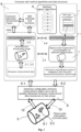
- the US measuring system for evaluating corrosion in the object under investigation comprises the following hardware-system components ( Fig. 1 ):
- US transducers and signals The US measurement system uses single-element US transducers or arrays of US transducers that form guided US waves.
- the operating frequencies of single-element US transducers and the frequency range of generated/received signals cover 30-200 kHz.
- Operating frequencies of multi-element US arrays can reach up to 1.5-2 MHz. In ultrasonic arrays, the number of elements can be from 1 to 16.
- An important feature of the invention is the scanning/measurement of the object under examination (9) with guided US waves.
- US transducers or arrays (8) are mounted on the test object (9) and excited to generate guided US waves (10) in the intended region of the object (9).
- Applications of guided US waves and their modes (longitudinal, flexural, and torsional) in corrosion research are known, for example, from the document [3].
- the system comprises the adaptively configurable US measurement system and the spatially distributed set of US converters or their arrays (8).
- This set comprises at least 1 transmitting US transducer and 1 receiving US transducer or arrays of US transducers installed on the test object (9), as well as US signal generators, amplifiers, analog-to-digital converters, etc.
- US transducers or their arrays (8) must be placed on the object under examination (9) and configured and controlled in such a way as to generate guided US waves in the intended region of the object under examination (9), the waves propagating in intended directions through the object under examination and suspected or to-be-checked corrosion damages in it;
- Guided US waves in the object under examination (9) can be generated in different modes, depending on the circumstances and limitations of the examination.
- the direction of excitation of the object (9) (pipe) can be selected as longitudinal, flexural, or torsional. Also, for example, the selection can be made with a dominant longitudinal symmetric or a dominant vertical direction asymmetric displacement component.
- the minimum US transducers configuration comprises 1 transmitting US transducer and 1 receiving US transducer installed at different selected (e.g. accessible) locations in the pipe.
- Such a minimal configuration allows studying the sector along the pipe, when the US transducers are not arranged in a circle around the pipe (perimeter), but in a spatially sparse manner along the pipe, as shown in Figures 4 b and c .
- the measurement system is then configured (calibrated) adaptively and automatically according to the US transducers placed on the surface of the pipe.
- Figure 4b shows single-element contact-type US converters (10.1, 10.2) for transmitting and receiving, wherein US receiver 10.2 mechanically scans along the pipe 9 to cover several spatial positions where the guided US waves 10 are recorded after their interaction with defects 9.1 and 9.2.
- Figure 4c shows single-element receivers 10.1 and 10.2 (1, 2, ..., N) arranged in different spatial positions, switched according to the selection algorithm operating in the US measurement system.
- the US measurement system comprises means (methodological steps) to adaptively configure the spatially distributed set of US transducers or their arrays (8).
- Corrosion assessment method implemented in the US measurement system comprises the following steps and data modules, which are also shown in Figure 2 :
- the sets of quantitative parameters are used in the corrosion assessment method.
- the invention provides the database (DB) of such sets of parameters containing many different sets. These sets of parameters are structural (geometric-material) descriptions of various possible (practically used) and measured pipe options.
- the finite element model of the pipe is created, in which the propagation of guided US waves of the selected mode is simulated, and the simulation result produces a virtual 3D-volume of the propagation of US guided waves in the digital model of the pipe.
- Said virtual 3D-volume can be compared with a tomographic 3D image of a real pipe, obtained by measuring the pipe with real propagated US guided waves and registered US signals.
- MDDM multidimensional data module
- This MDDM module can include errors between the measured pipe and its digital model, which can be minimized by optimizing the parameters of the digital model. Also, every inhomogeneity of the measured pipe is represented in the MDDM module, such as newly formed corrosion defects or cracks that are not present in the digital model.
- the initial set of quantitative parameters can be created from the results of the first US measurement, based on which the initial values of the quantitative parameters, such as pipe dimensions, material and damage characteristics, are estimated and recorded into the DB of quantitative parameter sets.
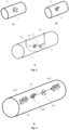
- Fig. 3 Types of corrosion. Different-type corrosion can form itself in the object under examination (pipe) ( Fig. 3 ), which is characterized by different structure of corrosion damage, interaction with US signals, and criticality for further operation of the pipe.
- Document [1] specifies at least two conditional types of corrosion: local and general corrosion. Local corrosion ( Fig. 3a ) refers to the damage of a small area with a significant thinning of the pipe wall thickness, that is, a corrosive depression (thinning), pits in the wall, or even a corrosion hole.
- the second type is general corrosion on the wall surface ( Figure 3b ), which involves a larger but shallow area of minor corrosive damage on the surface or volume of the wall.
- Tomographic reconstruction is performed from projections of US guided wave signals registered by US transducers or their arrays located in different spatial positions.
- US guided waves which had been propagated in the direction provided by the pipe wall and encountered defects in the propagation path, are registered in the receiving US transducer with changes in the US signal (reflections, attenuations, delay times, phase changes, influence caused by phase and group velocity dispersion).
- the obstacles encountered in the path of the US signal propagation their coordinates and characteristics are reconstructed, allowing the physical properties of the obstacle to be evaluated in further steps.
- the methods and means of tomographic reconstruction are not limited and freely chosen.
- PI software
Landscapes
- Physics & Mathematics (AREA)
- General Physics & Mathematics (AREA)
- Pathology (AREA)
- Life Sciences & Earth Sciences (AREA)
- Chemical & Material Sciences (AREA)
- Analytical Chemistry (AREA)
- Biochemistry (AREA)
- Health & Medical Sciences (AREA)
- General Health & Medical Sciences (AREA)
- Immunology (AREA)
- Engineering & Computer Science (AREA)
- Signal Processing (AREA)
- Acoustics & Sound (AREA)
- Artificial Intelligence (AREA)
- Evolutionary Computation (AREA)
- Investigating Or Analyzing Materials By The Use Of Ultrasonic Waves (AREA)
- Testing Resistance To Weather, Investigating Materials By Mechanical Methods (AREA)
Claims (15)
- Procédé d'examen par ultrasons, US, permettant d'évaluer des dommages causés par la corrosion dans un objet examiné (9), à l'aide d'un système de mesure US installé sur l'objet examiné (9), le procédé comprenant les étapes suivantes :• l'installation des transducteurs US émetteurs et récepteurs ou de leurs réseaux (10.1, 10.2) du système US sur l'objet examiné (9) et leur configuration pour propager les ondes US guidées (10) dans la région prévue de l'objet examiné (9) ;• l'excitation des transducteurs US émetteurs (10.1) par des signaux générés, et l'enregistrement des signaux d'ondes guidées US qui ont traversé l'objet examiné (9), l'enregistrement étant effectué par les transducteurs US récepteurs (10.2) ;• le prétraitement des signaux US enregistrés tels que filtrage, moyenne et segmentation par fenêtres temporelles ;• la reconstruction d'une image tomographique à partir des signaux US enregistrés, obtenant ainsi une image tomographique reconstruite ;• la comparaison de l'image tomographique reconstruite avec une image tomographique de référence et l'obtention d'une image tomographique différentielle ;• l'identification des dommages causés par la corrosion, dans laquellea) l'objet examiné (9) est un tuyau (9) ayant des parois d'une épaisseur ;b) les transducteurs US, au moins 1 transducteur US émetteur et au moins 1 transducteur US récepteur, sont répartis sur le tuyau (9), chacun par rapport à l'autre, au moins, le long du tuyau (9) sous inspection, pour diriger les ondes US guidées au moins le long du tuyau sous inspection ;c) la référence de l'objet examiné (9) est un modèle numérique (7) dudit tuyau (9), formé par modélisation informatique à partir d'un ensemble de paramètres quantitatifs (1.1), qui comprend les caractéristiques structurelles du tuyau (9), les caractéristiques des signaux US et leur propagation dans les parois du tuyau (9) ;d) dans l'étape de comparaison de la référence numérique (7) avec les résultats des mesures US, un module de données multidimensionnelles MDDM du tuyau (9) est formé, qui comprend une image tomographique différentielle du tuyau (9) et un ensemble de paramètres quantitatifs de celui-ci ;e) le procédé comprend au moins une étape d'apprentissage automatique ML, incluant au moins un endommagement par corrosion dans l'ensemble de paramètres quantitatifs de référence (1.1), ou au moins une fonction de régression ML correspondant à une distribution statistique de l'endommagement par la corrosion dans le tuyau (9) ;f) le procédé comprend au moins une étape de classification des dommages par corrosion, dans laquelle les dommages causés par la corrosion détectés dans le module MDDM sont classés à l'aide de fonctions ML, au minimum, en corrosion générale (9.1) et en corrosion localisée avec amincissement significatif de la paroi du tuyau (9.2).
- Procédé selon la revendication 1, dans lequel l'ensemble de paramètres quantitatifs (1.1) comprend au moins :• les caractéristiques structurelles de l'objet examiné (9) ;• les caractéristiques des convertisseurs ou réseaux US et leur positionnement sur l'objet examiné (9) ;• les caractéristiques de génération d'ondes guidées et de mesure du signal US ;• les caractéristiques des dommages causés par la corrosion de l'objet examiné (9) et/ou les fonctions statistiques et analytiques les décrivant.
- Procédé selon les revendications 1 et 2, dans lequel il utilise une base de données DB (1) comprenant plus d'un ensemble de paramètres quantitatifs (1.1).
- Procédé selon la revendication 1, dans lequel le module de données multidimensionnelles MDDM est formé, comprenant au moins :• une image tomographique différentielle obtenue en comparant l'image tomographique reconstruite de l'objet mesuré (9) et l'image tridimensionnelle du modèle numérique ;• un ensemble de paramètres quantitatifs identifiés à partir de l'image différentielle, comprenant les paramètres géométriques de l'endommagement par la corrosion détecté lors de la mesure pour l'objet (9).
- Procédé selon les revendications 1 et 4, dans lequel la surface, la longueur, la largeur et la profondeur des dommages corrosifs sur la paroi du tuyau sont les paramètres quantitatifs de la corrosion générale et locale évalués dans le résultat de mesure.
- Procédé selon l'une quelconque des revendications 1 à 3, dans lequel les ensembles de paramètres quantitatifs (1.1) et leur DB (1) sont formés par l'un quelconque des procédés suivants ou leur combinaison :• en saisissant et en ajustant manuellement les valeurs de l'ensemble des paramètres quantitatifs (1.1) ;• en saisissant des données statistiques sur les dommages corrosifs et des fonctions de régression-pronostic issues d'autres expériences, mesures et résultats de modélisation ;• en effectuant des mesures dans un nouvel objet inconnu et en accumulant des données historiques et statistiques de ses mesures.
- Procédé selon l'une quelconque des revendications 1 à 3, dans lequel l'ensemble de paramètres quantitatifs (1.1) pour mesurer l'objet est sélectionné par l'un quelconque des procédés suivants ou leur combinaison:• en saisissant et en ajustant manuellement les valeurs de l'ensemble des paramètres quantitatifs (1.1) ;• après avoir effectué une mesure US d'étalonnage de l'objet (9), en formant un ensemble de paramètres de mesure, et en fonction des différences minimales entre celle-ci et les ensembles DB, l'ensemble le plus proche de paramètres quantitatifs (1.1) est sélectionné ;• après la mesure d'étalonnage des US de l'objet, un ensemble de paramètres quantitatifs est formé à partir des résultats de cette mesure, qui est considéré comme l'ensemble de référence des paramètres quantitatifs (1.1), qui est également enregistré dans la base de données (1).
- Procédé selon la revendication 1, dans lequel la référence numérique (7) et la propagation des signaux US dans celle-ci sont modélisées par la méthode des éléments finis et les outils de modélisation logiciels correspondants.
- Procédé selon l'une quelconque des revendications 1 à 8, dans lequel il comprend en outre l'étape d'adaptation du système, qui, en fonction des mesures d'étalonnage effectuées par les transducteurs US installés sur l'objet examiné (9), ajuste les paramètres du modèle numérique (7) en minimisant les erreurs différentielles entre l'objet examiné (9) et le modèle numérique (7).
- Système de mesure par ultrasons, US, pour évaluer les dommages dus à la corrosion (9.1, 9.2) et configuré pour mettre en œuvre le procédé d'examen US selon les revendications 1 à 9, comprenant au moins• l'objet examiné (9) qui est un tuyau (3) dont les parois ont une épaisseur ;• au moins 1 transducteur US émetteur et 1 transducteur récepteur ou des réseaux de ceux-ci installés sur ledit tuyau (9) au moins l'un par rapport à l'autre le long du tuyau (9) sous inspection ;• des générateurs de signaux, amplificateurs et convertisseurs analogique-numérique US ;• un dispositif informatique (6), comprenant au moins un processeur et au moins un module mémoire, mettant en œuvre les structures de données du procédé d'examen US, les bases de données, et exécutant les étapes du procédé par programmation;
dans lequel dans le système• la référence de mesure est mise en œuvre par une référence numérique (7), formée par modélisation informatique en mémoire à partir d'un ensemble de paramètres quantitatifs (1.1), et• des transducteurs US ou leurs réseaux sont placés sur le tuyau (9) et configurés de manière à générer des ondes US guidées dans la région prévue du tuyau (9) se propageant dans des directions prévues à travers les dommages de corrosion examinés. - Système selon la revendication 10, dans lequel les ondes US guidées sont générées longitudinalement, en flexion ou en torsion (en rotation) dans les parois du tuyau mesuré (9), par rapport au tuyau (9), et également, une composante de déplacement symétrique longitudinale dominante est incluse.
- Système selon la revendication 10, dans lequel les fréquences efficaces des transducteurs US individuels ou de leurs réseaux, et des ondes US sont dans la plage de 30 kHz à 1,5 MHz.
- Système selon la revendication 10, dans lequel le nombre de cellules dans les réseaux de transducteurs US est de 2 à 16.
- Système selon la revendication 10, dans lequel dans la configuration minimale de 1 transducteur US émetteur et 1 transducteur US récepteur, le récepteur US (10.1) et/ou l'émetteur US (10.2) sont agencés pour un balayage mécanique le long de l'objet examiné, le tuyau (9), pour chevaucher plusieurs positions spatiales auxquelles les ondes US guidées sont enregistrées après leur interaction avec les défauts.
- Logiciel mettant en œuvre le procédé d'examen selon les revendications 1 à 9, à mettre en œuvre avec un système selon les revendications 10 à 14,
dans lequel il comprend des algorithmes informatiques et des modules logiciels qui mettent en œuvre les étapes suivantes :• la formation du modèle numérique de l'objet (7) à partir de l'ensemble qualitatif de paramètres (1.1), et la modélisation de la propagation des signaux d'ondes guidées US dans le modèle de l'objet (7) ;• l'étalonnage du système de mesure US avec l'objet examiné (9) avec le modèle numérique (7) ;• la sélection de l'ensemble des paramètres qualitatifs (1.1) à partir de la base de données (1) ;• la constitution de la base de données (1) des ensembles de paramètres qualitatifs (1.1) ;• la comparaison des résultats de mesure US avec le modèle numérique (7) et la formation du module de données multidimensionnelles MDDM.
Applications Claiming Priority (1)
| Application Number | Priority Date | Filing Date | Title |
|---|---|---|---|
| LT2022518A LT6977B (lt) | 2022-04-29 | 2022-04-29 | Ultragarsinės tomografijos būdas ir sistema vamzdynų korozijai įvertinti |
Publications (3)
| Publication Number | Publication Date |
|---|---|
| EP4269999A1 EP4269999A1 (fr) | 2023-11-01 |
| EP4269999C0 EP4269999C0 (fr) | 2025-06-25 |
| EP4269999B1 true EP4269999B1 (fr) | 2025-06-25 |
Family
ID=83931069
Family Applications (1)
| Application Number | Title | Priority Date | Filing Date |
|---|---|---|---|
| EP23169298.9A Active EP4269999B1 (fr) | 2022-04-29 | 2023-04-21 | Procédé et système de tomographie par ultrasons pour évaluer la corrosion d'une canalisation |
Country Status (2)
| Country | Link |
|---|---|
| EP (1) | EP4269999B1 (fr) |
| LT (1) | LT6977B (fr) |
Families Citing this family (6)
| Publication number | Priority date | Publication date | Assignee | Title |
|---|---|---|---|---|
| CN116008161B (zh) * | 2023-01-10 | 2025-03-14 | 西安东方宏业科技股份有限公司 | 一种管道腐蚀检测评价方法 |
| CN117387535A (zh) * | 2023-10-12 | 2024-01-12 | 中国舰船研究设计中心 | 一种船用动力管道壁厚减薄在线监测系统及方法 |
| CN118395860B (zh) * | 2024-04-29 | 2025-04-15 | 哈尔滨工业大学 | 一种导波频散关系恢复问题中优化测点布置的方法 |
| CN119147636A (zh) * | 2024-11-18 | 2024-12-17 | 河南鼎冠电力科技有限公司 | 电力杆塔内外腐蚀超声导波无损检测方法 |
| CN120948612B (zh) * | 2025-10-17 | 2026-03-06 | 浙江城建煤气热电设计院股份有限公司 | 一种热力管网腐蚀寿命预测方法 |
| CN121613004A (zh) * | 2026-02-03 | 2026-03-06 | 西安安泰电子科技有限公司 | 一种管道导波信号处理方法及系统 |
Family Cites Families (7)
| Publication number | Priority date | Publication date | Assignee | Title |
|---|---|---|---|---|
| US20070000328A1 (en) * | 2005-01-06 | 2007-01-04 | Jonathan Buttram | Ultrasonic method for the accurate measurement of crack height in dissimilar metal welds using phased array |
| GB0504500D0 (en) | 2005-03-04 | 2005-04-13 | Guided Ultrasonics Ltd | Signal processing arrangement |
| US8806944B2 (en) | 2009-09-18 | 2014-08-19 | Conocophillips Company | High precision ultrasonic corrosion rate monitoring |
| GB2482300A (en) | 2010-07-28 | 2012-02-01 | Guided Ultrasonics Ltd | Processing signals acquired during guided wave testing |
| GB2527954B (en) * | 2013-01-30 | 2019-01-16 | Univ Cincinnati | Measuring wall thickness loss for a structure |
| GB2545044B (en) | 2016-08-11 | 2018-02-07 | Guided Ultrasonics Ltd | Determining a thickness of a region of wall-or plate-like structure |
| US20210333238A1 (en) | 2020-04-27 | 2021-10-28 | Saudi Arabian Oil Company | Scale and corrosion monitoring system using ultrasonic guided waves |
-
2022
- 2022-04-29 LT LT2022518A patent/LT6977B/lt unknown
-
2023
- 2023-04-21 EP EP23169298.9A patent/EP4269999B1/fr active Active
Also Published As
| Publication number | Publication date |
|---|---|
| EP4269999C0 (fr) | 2025-06-25 |
| LT6977B (lt) | 2023-01-25 |
| EP4269999A1 (fr) | 2023-11-01 |
| LT2022518A (lt) | 2022-11-10 |
Similar Documents
| Publication | Publication Date | Title |
|---|---|---|
| EP4269999B1 (fr) | Procédé et système de tomographie par ultrasons pour évaluer la corrosion d'une canalisation | |
| KR101225244B1 (ko) | 자동 빔 집속 장치 및 이를 이용한 비파괴 검사 방법 | |
| EP2791628B1 (fr) | Données d'ondes de lamb soumises à un traitement de signal pour inspecter un tuyau | |
| US12235100B2 (en) | Methods and systems for determining a thickness of an elongate or extended structure | |
| Saini et al. | Optimisation of the half-skip total focusing method (HSTFM) parameters for sizing surface-breaking cracks | |
| Hampson et al. | Modelling and characterisation ultrasonic phased array transducers for pipe inspections | |
| Zhang et al. | Pipe inspection using guided acoustic wave sensors integrated with mobile robots | |
| Hu et al. | Tomographic reconstruction of damage images in hollow cylinders using Lamb waves | |
| Cao et al. | A correlation-based approach to corrosion detection with lamb wave mode cutoff | |
| CN103097884B (zh) | 用于测定机械部件中存在的缺陷的方位的方法和装置 | |
| Ranjbar Naserabadi et al. | Application of phased array ultrasonic transducers for guided wave scanning of plates using multi-point focusing technique | |
| Ouabi et al. | Learning the propagation properties of rectangular metal plates for Lamb wave-based mapping | |
| US7654142B2 (en) | Method of imaging using topologic energy calculation | |
| Clough et al. | Evaluating an SH wave EMAT system for pipeline screening and extending into quantitative defect measurements | |
| Kwan et al. | TFM Acoustic Influence Map | |
| Monnier et al. | Guided wave topological energy method for quantitative evaluation of corrosion in metal plates and tubes | |
| Budyn | Imaging and defect characterisation using multi-view ultrasonic data in nondestructive evaluation | |
| Volker et al. | Ultrasonic multi-skip tomography for pipe inspection | |
| Engle | Quantitative flaw characterization with ultrasonic phased arrays | |
| RAVI et al. | Ultrasonic Guided Wave Simulation Performance Evaluation for QNDE-SHM Processes | |
| Yu et al. | MICROSTRUCTURE-INDUCED ULTRASONIC SIGNAL FLUCTUATIONS IN TITANIUM ALLOY | |
| Zhang | Defect detection, classification, and characterization using ultrasound | |
| Wang et al. | Development of an ultrasonic system for composite material inspection | |
| Rachev et al. | Ultrasonic immersion testing for depth sizing of crack-like defects in large diameter pipes | |
| Shakibi | Resolution enhancement of ultrasonic signals using autoregressive spectral extrapolation |
Legal Events
| Date | Code | Title | Description |
|---|---|---|---|
| PUAI | Public reference made under article 153(3) epc to a published international application that has entered the european phase |
Free format text: ORIGINAL CODE: 0009012 |
|
| STAA | Information on the status of an ep patent application or granted ep patent |
Free format text: STATUS: THE APPLICATION HAS BEEN PUBLISHED |
|
| AK | Designated contracting states |
Kind code of ref document: A1 Designated state(s): AL AT BE BG CH CY CZ DE DK EE ES FI FR GB GR HR HU IE IS IT LI LT LU LV MC ME MK MT NL NO PL PT RO RS SE SI SK SM TR |
|
| STAA | Information on the status of an ep patent application or granted ep patent |
Free format text: STATUS: REQUEST FOR EXAMINATION WAS MADE |
|
| 17P | Request for examination filed |
Effective date: 20240201 |
|
| RBV | Designated contracting states (corrected) |
Designated state(s): AL AT BE BG CH CY CZ DE DK EE ES FI FR GB GR HR HU IE IS IT LI LT LU LV MC ME MK MT NL NO PL PT RO RS SE SI SK SM TR |
|
| GRAP | Despatch of communication of intention to grant a patent |
Free format text: ORIGINAL CODE: EPIDOSNIGR1 |
|
| STAA | Information on the status of an ep patent application or granted ep patent |
Free format text: STATUS: GRANT OF PATENT IS INTENDED |
|
| INTG | Intention to grant announced |
Effective date: 20250404 |
|
| GRAS | Grant fee paid |
Free format text: ORIGINAL CODE: EPIDOSNIGR3 |
|
| GRAA | (expected) grant |
Free format text: ORIGINAL CODE: 0009210 |
|
| STAA | Information on the status of an ep patent application or granted ep patent |
Free format text: STATUS: THE PATENT HAS BEEN GRANTED |
|
| AK | Designated contracting states |
Kind code of ref document: B1 Designated state(s): AL AT BE BG CH CY CZ DE DK EE ES FI FR GB GR HR HU IE IS IT LI LT LU LV MC ME MK MT NL NO PL PT RO RS SE SI SK SM TR |
|
| REG | Reference to a national code |
Ref country code: GB Ref legal event code: FG4D |
|
| REG | Reference to a national code |
Ref country code: CH Ref legal event code: EP |
|
| REG | Reference to a national code |
Ref country code: DE Ref legal event code: R096 Ref document number: 602023004211 Country of ref document: DE |
|
| REG | Reference to a national code |
Ref country code: CH Ref legal event code: EP |
|
| REG | Reference to a national code |
Ref country code: IE Ref legal event code: FG4D |
|
| U01 | Request for unitary effect filed |
Effective date: 20250628 |
|
| U07 | Unitary effect registered |
Designated state(s): AT BE BG DE DK EE FI FR IT LT LU LV MT NL PT RO SE SI Effective date: 20250704 |
|
| PG25 | Lapsed in a contracting state [announced via postgrant information from national office to epo] |
Ref country code: GR Free format text: LAPSE BECAUSE OF FAILURE TO SUBMIT A TRANSLATION OF THE DESCRIPTION OR TO PAY THE FEE WITHIN THE PRESCRIBED TIME-LIMIT Effective date: 20250926 Ref country code: NO Free format text: LAPSE BECAUSE OF FAILURE TO SUBMIT A TRANSLATION OF THE DESCRIPTION OR TO PAY THE FEE WITHIN THE PRESCRIBED TIME-LIMIT Effective date: 20250925 |
|
| PG25 | Lapsed in a contracting state [announced via postgrant information from national office to epo] |
Ref country code: HR Free format text: LAPSE BECAUSE OF FAILURE TO SUBMIT A TRANSLATION OF THE DESCRIPTION OR TO PAY THE FEE WITHIN THE PRESCRIBED TIME-LIMIT Effective date: 20250625 |
|
| PG25 | Lapsed in a contracting state [announced via postgrant information from national office to epo] |
Ref country code: RS Free format text: LAPSE BECAUSE OF FAILURE TO SUBMIT A TRANSLATION OF THE DESCRIPTION OR TO PAY THE FEE WITHIN THE PRESCRIBED TIME-LIMIT Effective date: 20250925 |
|
| PG25 | Lapsed in a contracting state [announced via postgrant information from national office to epo] |
Ref country code: IS Free format text: LAPSE BECAUSE OF FAILURE TO SUBMIT A TRANSLATION OF THE DESCRIPTION OR TO PAY THE FEE WITHIN THE PRESCRIBED TIME-LIMIT Effective date: 20251025 |
|
| PG25 | Lapsed in a contracting state [announced via postgrant information from national office to epo] |
Ref country code: SM Free format text: LAPSE BECAUSE OF FAILURE TO SUBMIT A TRANSLATION OF THE DESCRIPTION OR TO PAY THE FEE WITHIN THE PRESCRIBED TIME-LIMIT Effective date: 20250625 |
|
| PG25 | Lapsed in a contracting state [announced via postgrant information from national office to epo] |
Ref country code: CZ Free format text: LAPSE BECAUSE OF FAILURE TO SUBMIT A TRANSLATION OF THE DESCRIPTION OR TO PAY THE FEE WITHIN THE PRESCRIBED TIME-LIMIT Effective date: 20250625 |
|
| PG25 | Lapsed in a contracting state [announced via postgrant information from national office to epo] |
Ref country code: PL Free format text: LAPSE BECAUSE OF FAILURE TO SUBMIT A TRANSLATION OF THE DESCRIPTION OR TO PAY THE FEE WITHIN THE PRESCRIBED TIME-LIMIT Effective date: 20250625 |
|
| PG25 | Lapsed in a contracting state [announced via postgrant information from national office to epo] |
Ref country code: SK Free format text: LAPSE BECAUSE OF FAILURE TO SUBMIT A TRANSLATION OF THE DESCRIPTION OR TO PAY THE FEE WITHIN THE PRESCRIBED TIME-LIMIT Effective date: 20250625 |
|
| PG25 | Lapsed in a contracting state [announced via postgrant information from national office to epo] |
Ref country code: ES Free format text: LAPSE BECAUSE OF FAILURE TO SUBMIT A TRANSLATION OF THE DESCRIPTION OR TO PAY THE FEE WITHIN THE PRESCRIBED TIME-LIMIT Effective date: 20250625 |
|
| PLBE | No opposition filed within time limit |
Free format text: ORIGINAL CODE: 0009261 |
|
| STAA | Information on the status of an ep patent application or granted ep patent |
Free format text: STATUS: NO OPPOSITION FILED WITHIN TIME LIMIT |