EP4270697A1 - Accessoire électrique hygiénique - Google Patents
Accessoire électrique hygiénique Download PDFInfo
- Publication number
- EP4270697A1 EP4270697A1 EP23155861.0A EP23155861A EP4270697A1 EP 4270697 A1 EP4270697 A1 EP 4270697A1 EP 23155861 A EP23155861 A EP 23155861A EP 4270697 A1 EP4270697 A1 EP 4270697A1
- Authority
- EP
- European Patent Office
- Prior art keywords
- seal
- connector
- shoulder
- seal member
- segment
- Prior art date
- Legal status (The legal status is an assumption and is not a legal conclusion. Google has not performed a legal analysis and makes no representation as to the accuracy of the status listed.)
- Pending
Links
Images








Classifications
-
- H—ELECTRICITY
- H01—ELECTRIC ELEMENTS
- H01R—ELECTRICALLY-CONDUCTIVE CONNECTIONS; STRUCTURAL ASSOCIATIONS OF A PLURALITY OF MUTUALLY-INSULATED ELECTRICAL CONNECTING ELEMENTS; COUPLING DEVICES; CURRENT COLLECTORS
- H01R13/00—Details of coupling devices of the kinds covered by groups H01R12/70 or H01R24/00 - H01R33/00
- H01R13/46—Bases; Cases
- H01R13/52—Dustproof, splashproof, drip-proof, waterproof, or flameproof cases
- H01R13/5219—Sealing means between coupling parts, e.g. interfacial seal
-
- H—ELECTRICITY
- H02—GENERATION; CONVERSION OR DISTRIBUTION OF ELECTRIC POWER
- H02G—INSTALLATION OF ELECTRIC CABLES OR LINES, OR OF COMBINED OPTICAL AND ELECTRIC CABLES OR LINES
- H02G3/00—Installations of electric cables or lines or protective tubing therefor in or on buildings, equivalent structures or vehicles
- H02G3/02—Details
- H02G3/06—Joints for connecting lengths of protective tubing or channels, to each other or to casings, e.g. to distribution boxes; Ensuring electrical continuity in the joint
- H02G3/0616—Joints for connecting tubing to casing
- H02G3/0625—Joints for connecting tubing to casing with means for preventing disengagement of conductors
- H02G3/0675—Joints for connecting tubing to casing with means for preventing disengagement of conductors with bolts operating in a direction parallel to the conductors
-
- F—MECHANICAL ENGINEERING; LIGHTING; HEATING; WEAPONS; BLASTING
- F16—ENGINEERING ELEMENTS AND UNITS; GENERAL MEASURES FOR PRODUCING AND MAINTAINING EFFECTIVE FUNCTIONING OF MACHINES OR INSTALLATIONS; THERMAL INSULATION IN GENERAL
- F16L—PIPES; JOINTS OR FITTINGS FOR PIPES; SUPPORTS FOR PIPES, CABLES OR PROTECTIVE TUBING; MEANS FOR THERMAL INSULATION IN GENERAL
- F16L19/00—Joints in which sealing surfaces are pressed together by means of a member, e.g. a swivel nut, screwed on, or into, one of the joint parts
- F16L19/06—Joints in which sealing surfaces are pressed together by means of a member, e.g. a swivel nut, screwed on, or into, one of the joint parts in which radial clamping is obtained by wedging action on non-deformed pipe ends
- F16L19/065—Joints in which sealing surfaces are pressed together by means of a member, e.g. a swivel nut, screwed on, or into, one of the joint parts in which radial clamping is obtained by wedging action on non-deformed pipe ends the wedging action being effected by means of a ring
-
- F—MECHANICAL ENGINEERING; LIGHTING; HEATING; WEAPONS; BLASTING
- F16—ENGINEERING ELEMENTS AND UNITS; GENERAL MEASURES FOR PRODUCING AND MAINTAINING EFFECTIVE FUNCTIONING OF MACHINES OR INSTALLATIONS; THERMAL INSULATION IN GENERAL
- F16L—PIPES; JOINTS OR FITTINGS FOR PIPES; SUPPORTS FOR PIPES, CABLES OR PROTECTIVE TUBING; MEANS FOR THERMAL INSULATION IN GENERAL
- F16L33/00—Arrangements for connecting hoses to rigid members; Rigid hose-connectors, i.e. single members engaging both hoses
- F16L33/18—Arrangements for connecting hoses to rigid members; Rigid hose-connectors, i.e. single members engaging both hoses characterised by the use of additional sealing means
-
- H—ELECTRICITY
- H02—GENERATION; CONVERSION OR DISTRIBUTION OF ELECTRIC POWER
- H02G—INSTALLATION OF ELECTRIC CABLES OR LINES, OR OF COMBINED OPTICAL AND ELECTRIC CABLES OR LINES
- H02G3/00—Installations of electric cables or lines or protective tubing therefor in or on buildings, equivalent structures or vehicles
- H02G3/02—Details
- H02G3/06—Joints for connecting lengths of protective tubing or channels, to each other or to casings, e.g. to distribution boxes; Ensuring electrical continuity in the joint
- H02G3/0616—Joints for connecting tubing to casing
- H02G3/0625—Joints for connecting tubing to casing with means for preventing disengagement of conductors
- H02G3/0666—Joints for connecting tubing to casing with means for preventing disengagement of conductors with means clamping the armour of the conductor
-
- H—ELECTRICITY
- H02—GENERATION; CONVERSION OR DISTRIBUTION OF ELECTRIC POWER
- H02G—INSTALLATION OF ELECTRIC CABLES OR LINES, OR OF COMBINED OPTICAL AND ELECTRIC CABLES OR LINES
- H02G3/00—Installations of electric cables or lines or protective tubing therefor in or on buildings, equivalent structures or vehicles
- H02G3/02—Details
- H02G3/08—Distribution boxes; Connection or junction boxes
- H02G3/088—Dustproof, splashproof, drip-proof, waterproof, or flameproof casings or inlets
Definitions
- liquid-tight electrical fittings are used in manufacturing areas that require a high level of cleanliness.
- the industries' greatest priority is the elimination or reduction of contamination of manufactured products and pharmaceuticals.
- product or intermittent cleaning solution may routinely escape production equipment, creating a "splash-zone" within the vicinity of the product being produced.
- areas near production equipment are routinely washed down by operators to remove potentially harmful contaminants.
- Liquid-tight electrical fittings used within a splash-zone and wash-down environment must meet strict hygienic design requirements of specialized standards such as NSF 169 and EN 1672-2. Typically, standard liquid-tight fittings do not meet these requirements.
- a liquid-tight fitting in one aspect, includes a connector, a seal member formed of an elastically deformable material, and a fastener member.
- the connector has a first end, a second end, a shoulder located between the first end and the second end, and a first segment that extends from the shoulder to the first end.
- the first segment has an outer surface.
- the first seal member surrounds a portion of the first segment adjacent the shoulder, and has an inner surface in contact with the outer surface of the first segment, an outer edge opposite the inner surface, and first and second seal ends that join the inner surface and the outer edge, where the first seal end abuts against the shoulder.
- the fastener member is moveably secured to the first end of the connector, and has an end that engages the second seal end to cause the first seal member to form a compressive seal between the shoulder and the fastener member.
- the first seal member is adapted to deform toward the first segment when the end of the fastener member engages the second seal end.
- a liquid-tight fitting in another aspect, includes a connector, a ground cone, a first seal member, a gland nut, and a second seal member.
- the connector has a first end adapted to receive a conduit, a second end adapted to attach to an electrical enclosure, a central bore that extends therethrough, a shoulder located between the first end and the second end, a first segment that extends from the shoulder to the first end, and a second segment that extends from the shoulder to the second end.
- the ground cone is positioned within the central bore at the first end of the connector.
- the first and second seal members are formed of an elastically deformable material. The first seal member surrounds a portion of the first segment adjacent the shoulder.
- the second seal member surrounds a portion of the second segment adjacent the shoulder.
- the gland nut is moveably secured to the first end of the connector, and has an end that engages the first seal member to cause the first seal member to form a compressive seal between the shoulder and the gland nut.
- the second seal member is adapted to form a compressive seal between the shoulder and the electrical enclosure.
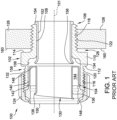
- FIG. 1 shows a longitudinal cross-sectional view of a liquid-tight fitting 100.
- fitting generally refers to an electrical coupling element that is used to connect insulated cables or conduits to electrical enclosures such as an electrical panel, a junction box, or the like.
- liquid-tight generally refers to a fitting that maintains the liquid-tight integrity of the conduit at the point where the conduit is connected to the electrical enclosure.
- a liquid tight fitting is a fitting that includes a means for preventing the undesirable flow of liquid into the interior of the fitting.
- Liquid-tight fitting 100 includes a connector 102 that has a longitudinal axis 101, a first connector end 104, and a second connector end 106.
- Connector 102 is open at both ends 104 and 106 and has a central bore 108 extending therethrough.
- Connector 102 also has a shoulder 110 located between first connector end 104 and second connector end 106. Shoulder 110 extends circumferentially and radially outwardly along the exterior of connector 102. Shoulder 110 has a first radial surface 112 directed toward first connector end 104 and a second radial surface 114 directed toward second connector end 106.
- Gland nut 124 includes a tail end 146 and head end 148 that are joined by a gland nut wall that includes a threaded portion along the interior of the wall. Gland nut 124 is threadably secured to connector 102 at first connector end 104. Head end 148 projects in a radially inward direction toward axis 101 and has an internal surface (not shown) directed toward first connector end 104 when gland nut 124 is secured to first connector segment 116.
- insulating sleeve 152 is inserted within central bore 108 at second connector end 106.
- Insulating sleeve 152 has a first sleeve end 154 that is flush with or extends slightly beyond second connector end 106 and a second sleeve end 156 that terminates proximate shelf 134.
- liquid-tight fitting 100 does not include insulating sleeve 152.
- the compressed gasket 150 prevents gland nut 124 from being fully tightened onto first connector segment 116.
- a space 158 is defined between tail end 146 of gland nut 124 and first radial surface 112 of shoulder 110. External threads formed along outer surface 120 of first connector segment 116 are exposed by space 158.
- First sidewall 218 is oriented adjacent external surface 160 of wall 126 and second sidewall 220 is oriented adjacent second radial surface 114 of shoulder 110.
- Inner surface 214 contacts outer surface 122 of second connector segment 118 when second annular member 204 surrounds second connector segment 118.
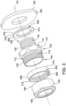
- first annular member 202 When gland nut 124 is moveably secured to first connector end 104, tail end 146 of gland nut 124 contacts second sidewall 212 of first annular member 202.
- the elastically deformable first annular member 202 is compressed between tail end 146 and first radial surface 112 of shoulder 110 and forms a compressive seal therebetween.
- the compressive seal formed by first annular member 202 thereby prevents an ingress of unwanted contaminants, such as liquid from production equipment or a wash-down operation, into space 158 formed between tail end 146 and first radial surface 112.
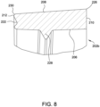
- FIG. 6 shows a cross-sectional view of a first example embodiment of first annular member 202, designated as first annular member 202a, taken along line 5-5 shown in FIG. 5 .
- first annular member 202a has a generally rectangular cross-section defined by inner surface 206, outer edge 208, first sidewall 210, and second sidewall 212. The cross-section is the same along the entire first annular member 202a.
- FIG. 7 shows a magnified view of section portion A shown in FIG. 6 , and illustrates in detail additional features of the cross-section of first annular member 202a. As shown in FIG.
- inner surface 206 of first annular member 202a is substantially planar as inner surface 206 extends between first and second sidewalls 210 and 212.
- inner surface 206 may be a non-planar surface, for example, inner surface 206 may be a convex surface or concave surface.
- Inner surface 206 has a length between first and second sidewalls 210 and 212 that is greater than the longitudinal dimension of space 158 (shown in FIG. 1 ).
- An annularly extending notch 222 is formed in second sidewall 212. Notch 222 is dimensioned to match a contoured surface of tail end 146 of gland nut 124 that engages second sidewall 212, such that tail end 146 sealingly engages second sidewall 212.
- first annular member 202 at second sidewall 212 may therefore also be adjusted to facilitate suitable deformation characteristics as described herein.
- a contoured profile of second sidewall 212 e.g., a radius of notch 222 to suitably match that of tail end 146 of gland nut 124, may therefore also be adjusted to facilitate suitable deformation characteristics as described herein.
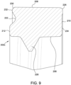
- first annular member 202d A third alternative embodiment of first annular member 202, designated as first annular member 202d, is shown in magnified cross-sectional view in FIG. 10 .
- First annular member 202d may be intended for use with liquid-tight fitting 200 that includes connector 102 having a 3 ⁇ 4-inch inner diameter at first connector end 104.
- First annular member 202d includes the same features and elements of first annular member 202c (shown in FIG. 9 ), with suitable dimensions for the alternatively sized connector 102.
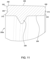
- first annular member 202e is shown in magnified cross-sectional view in FIG. 11 .
- First annular member 202e may be intended for use with liquid-tight fitting 200 that includes connector 102 having a 1 ⁇ 2-inch inner diameter at first connector end 104.
- First annular member 202e includes the same features and elements of first annular member 202c (shown in FIG.
- first annular member 202f A fifth alternative embodiment of first annular member 202, designated as first annular member 202f, is shown in magnified cross-sectional view in FIG. 12 .
- First annular member 202f may be intended for use with liquid-tight fitting 200 that includes connector 102 having a 2-inch inner diameter at first connector end 104.
- First annular member 202f includes the same features and elements of first annular member 202c (shown in FIG. 9 ), with suitable dimensions for the alternatively sized connector 102.
- First annular member 202f also has a first sidewall 210 that does not include a recessed portion.
- first annular member 202g A sixth alternative embodiment of first annular member 202, designated as first annular member 202g, is shown in magnified cross-sectional view in FIG. 13 .
- First annular member 202g may be intended for use with liquid-tight fitting 200 that includes connector 102 having a 1-inch inner diameter at first connector end 104.
- First annular member 202g includes the same features and elements of first annular member 202d (shown in FIG. 10 ), with suitable dimensions for the alternatively sized connector 102.
- First annular member 202g also has a first sidewall 210 that does not include a recessed portion.
- inner surface 214 of second annular member 204 defines an inner diameter D2 that is suitably dimensioned to enable inner surface 214 to contact outer surface 122 of second connector segment 118 and hold second annular member 204 in place when second annular member 204 is positioned along second connector segment 118.
- the length of inner diameter D2 is determined by a thread size of second connector segment 118 which is suitably dimensioned to secure connector 102 to wall 126.
- the inner diameter D2 of second annular member 204 is therefore not intended to be limited to any particular size, and second annular member 204 is contemplated to be used with liquid-tight fittings 200 of various sizes.
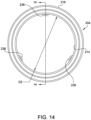
- Inner surface 214 also includes a set of circumferentially-spaced ribs 236 that project in a radially-inward direction. Ribs 236 may engage and grip threads formed along outer surface 122 of second connector segment 118 and prevent longitudinal movement of second annular member 204 along axis 101 when second annular member 204 is positioned around second connector segment 118.
- inner surface 214 includes three ribs 236 that are circumferentially-spaced equal distances along inner surface 214. In other embodiments, more or fewer ribs 236 than the three ribs disclosed may be formed on inner surface 214, and may be spaced in any suitable manner to provide the function described herein.
- FIG. 15 shows a cross-sectional view of a first example embodiment of second annular member 204, designated as second annular member 204a, taken along line 14-14 shown in FIG. 14 .
- second annular member 204a has a generally rectangular cross-section defined by inner surface 214, outer edge 216, first sidewall 218, and second sidewall 220.
- the cross-section defined by outer edge 216 and first and second sidewalls 218 and 220 is the same along the entire second annular member 204a, and the cross-section defined by inner surface 214 is the same at portions where ribs 236 are formed and is the same at portions without ribs 236.
- FIG. 16 shows a magnified view of section portion B shown in FIG.
- outer edge 216 of second annular member 204a is substantially planar.
- Inner surface 214 and outer edge 216 have a substantially equal length between first and second sidewalls 218 and 220.
- the length of inner surface 214 and outer edge 216 is suitably larger than the longitudinal dimension of crevice 128 (shown in FIG. 1 ).
- First sidewall 218 extends between a first radius edge 238, formed at the intersection of first sidewall 218 and outer edge 216, and a second radius edge 240, formed at the intersection of first sidewall 218 and inner surface 214.
- First sidewall 218 has a first recessed portion 242 proximate first radius edge 238 and a second recessed portion 244 proximate second radius edge 240.
- First and second recessed portions 242 and 244 extend between outward projecting portions of first sidewall 218.
- Second sidewall 220 extends between a first radius edge 246, formed at the intersection of second sidewall 218 and outer edge 216, and a second radius edge 248, formed at the intersection of second sidewall 220 and inner surface 214.
- Second sidewall 220 has a first recessed portion 250 proximate first radius edge 246 and a second recessed portion 252 proximate second radius edge 248.
- First and second recessed portions 250 and 252 extend between outward projecting portions of second sidewall 220.
- first and second sidewalls 218 and 220 may engage and grip the respective second axial surface 114 and external surface 160 and prevent the elastically deformable material of second annular member 204a from substantially moving radially outward away from axis 101 when second annular member 204a is compressed.
- Rib 236 has a first portion 254 adjacent inner surface 214 that has a rectangular cross section, and a second portion 256 opposite inner surface 214 that has a V-shaped cross section. Second portion 256 is sized and shaped to fit within a crevice formed by the external threads along outer surface 122 of second connector segment 118.
- FIG. 17 shows a magnified view of a portion of the cross-section of second annular member 204 taken along line 14-14 (shown in FIG. 14 ) that is similar to section portion B of first annular member 204a shown in FIG. 15 .
- Second annular member 204b may be intended for use with liquid-tight fitting 200 that includes connector 102 having a different diameter at second connector end 106 than a liquid-tight fitting 200 with which second annular member 204a is intended for use.
- Second annular member 204b includes the same features and elements of second annular member 204a (shown in FIG. 16 ), with suitable dimensions for the alternatively sized connector 102.
- Second shoulder 166 includes the same features described above for shoulder 110, and first annular member 202 compressively seals space 158 (shown in FIG. 1 ) between gland nut 124 and second shoulder 166 as described herein.
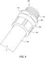
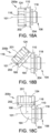
- Central elbow portion 164 is curved relative to axis 101 such that first connector end 104 (shown in FIG. 2 ) is axially off-set from second connector end 106.
- First connector end 104 is axially aligned along axis 201, which forms angle ⁇ with axis 101.
- first annular member 202 is axially off-set from second annular member 204 by angle ⁇ .
- angle ⁇ may be about a 45° angle (as is the case for liquid-tight fitting 200b shown in FIG.
- angle ⁇ may be any suitable angle of an elbow-shaped connector 102 known in the art, typically an angle between 0° and 90°.
- the recitation of "at least one of A, B and C” should be interpreted as one or more of a group of elements consisting of A, B and C, and should not be interpreted as requiring at least one of each of the listed elements A, B and C, regardless of whether A, B and C are related as categories or otherwise.
- the recitation of "A, B and/or C" or "at least one of A, B or C” should be interpreted as including any singular entity from the listed elements, e.g., A, any subset from the listed elements, e.g., A and B, or the entire list of elements A, B and C.
Landscapes
- Engineering & Computer Science (AREA)
- General Engineering & Computer Science (AREA)
- Mechanical Engineering (AREA)
- Architecture (AREA)
- Civil Engineering (AREA)
- Structural Engineering (AREA)
- Quick-Acting Or Multi-Walled Pipe Joints (AREA)
- Gasket Seals (AREA)
Applications Claiming Priority (1)
| Application Number | Priority Date | Filing Date | Title |
|---|---|---|---|
| US17/669,028 US12230912B2 (en) | 2022-02-10 | 2022-02-10 | Hygienic electrical fitting with seal members |
Publications (1)
| Publication Number | Publication Date |
|---|---|
| EP4270697A1 true EP4270697A1 (fr) | 2023-11-01 |
Family
ID=85222469
Family Applications (1)
| Application Number | Title | Priority Date | Filing Date |
|---|---|---|---|
| EP23155861.0A Pending EP4270697A1 (fr) | 2022-02-10 | 2023-02-09 | Accessoire électrique hygiénique |
Country Status (4)
| Country | Link |
|---|---|
| US (1) | US12230912B2 (fr) |
| EP (1) | EP4270697A1 (fr) |
| CN (1) | CN116581593A (fr) |
| CA (1) | CA3189112A1 (fr) |
Citations (4)
| Publication number | Priority date | Publication date | Assignee | Title |
|---|---|---|---|---|
| JPH07103379A (ja) * | 1993-10-01 | 1995-04-18 | Tokyo Gas Co Ltd | フレキシブル管用継手 |
| US7183486B2 (en) * | 2005-07-21 | 2007-02-27 | Thomas & Betts International, Inc. | Liquid-tight connector with deformable o-ring |
| DE202010006985U1 (de) * | 2010-05-14 | 2010-08-19 | AVC Industrial Corp., Wuku | Wasserdichtes Fixierstück mit doppelten Klemmen für Stromkabel und Wellenrohr |
| US20140145436A1 (en) * | 2012-11-26 | 2014-05-29 | Lapp Engineering & Co. | Feed-through device |
Family Cites Families (8)
| Publication number | Priority date | Publication date | Assignee | Title |
|---|---|---|---|---|
| US7390027B2 (en) * | 2003-08-13 | 2008-06-24 | Bridgeport Fittings, Inc. | Weatherproof compression connecting assembly for securing electrical metal tubing |
| US20090179388A1 (en) * | 2008-01-15 | 2009-07-16 | Uhlenkamp Brian J | Hygienic Coupling and Fitting Seal System |
| US20100084855A1 (en) | 2008-10-07 | 2010-04-08 | Thomas & Betts International, Inc. | Economy liquidtight fitting |
| WO2010129756A1 (fr) * | 2009-05-08 | 2010-11-11 | Swagelok Company | Raccord de conduit auquel est fixé un collier d'application de couple |
| US20120074694A1 (en) * | 2009-06-08 | 2012-03-29 | Hygienic Design Group Llc | Self-aligning sanitary pipe joints and related systems |
| US8910980B2 (en) | 2011-11-08 | 2014-12-16 | Thomas & Betts International, Inc. | Liquid-tight fitting |
| EP3913270B1 (fr) | 2020-05-19 | 2023-07-26 | ABB Schweiz AG | Système de couplage hygiénique |
| US12259080B2 (en) * | 2021-02-04 | 2025-03-25 | Universal Moulding Co. Ltd. | Pipe thread protector with removable end member and interference-fit protrusion |
-
2022
- 2022-02-10 US US17/669,028 patent/US12230912B2/en active Active
-
2023
- 2023-02-09 EP EP23155861.0A patent/EP4270697A1/fr active Pending
- 2023-02-09 CN CN202310089315.7A patent/CN116581593A/zh active Pending
- 2023-02-09 CA CA3189112A patent/CA3189112A1/fr active Pending
Patent Citations (4)
| Publication number | Priority date | Publication date | Assignee | Title |
|---|---|---|---|---|
| JPH07103379A (ja) * | 1993-10-01 | 1995-04-18 | Tokyo Gas Co Ltd | フレキシブル管用継手 |
| US7183486B2 (en) * | 2005-07-21 | 2007-02-27 | Thomas & Betts International, Inc. | Liquid-tight connector with deformable o-ring |
| DE202010006985U1 (de) * | 2010-05-14 | 2010-08-19 | AVC Industrial Corp., Wuku | Wasserdichtes Fixierstück mit doppelten Klemmen für Stromkabel und Wellenrohr |
| US20140145436A1 (en) * | 2012-11-26 | 2014-05-29 | Lapp Engineering & Co. | Feed-through device |
Also Published As
| Publication number | Publication date |
|---|---|
| US12230912B2 (en) | 2025-02-18 |
| US20230253729A1 (en) | 2023-08-10 |
| CA3189112A1 (fr) | 2023-08-10 |
| CN116581593A (zh) | 2023-08-11 |
Similar Documents
| Publication | Publication Date | Title |
|---|---|---|
| US8766109B2 (en) | Cable connector with bushing element | |
| US6976872B1 (en) | Coaxial connector | |
| US7753705B2 (en) | Flexible RF seal for coaxial cable connector | |
| RU2305886C2 (ru) | Герметизированный коаксиальный кабельный соединитель и связанный с ним способ | |
| US7438327B2 (en) | Electrical connection assembly with unitary sealing and compression ring | |
| US7976070B2 (en) | Weatherproof compression connecting assembly for securing electrical metal tubing | |
| US20210351576A1 (en) | Press fitting for electrical conduit | |
| US8445782B2 (en) | Flexible conduit coupling connector | |
| US20120196464A1 (en) | Water seal connector | |
| US9647439B1 (en) | Liquid-tight and concrete-tight fitting for PVC jacketed metal-clad electrical cable | |
| US10483735B1 (en) | Ninety degree snap fit electrical fitting for connection of electrical cables to an electrical box | |
| US20210091518A1 (en) | Coaxial cable connector having braid positioning elements and f-type female port with snap-in features | |
| US4848804A (en) | Dielectric coupling | |
| US5098310A (en) | Electrical connector assembly with improved water seal | |
| EP2390963A1 (fr) | Connecteur, ensemble de connecteur et procédé de production de connecteur | |
| US12230912B2 (en) | Hygienic electrical fitting with seal members | |
| US8475192B2 (en) | Bushing seal for reefer plug | |
| US10811863B1 (en) | Liquid-tight and concrete-tight fitting for PVC-jacketed metal-clad electrical cable | |
| CN106134011B (zh) | 高压电缆插头 | |
| US20190145557A1 (en) | Connecting device, in particular in the form of a hose coupling | |
| CN101800367B (zh) | 同轴电缆连接器 | |
| US20080079258A1 (en) | Irrigation sprinkler adapter | |
| CA3065033C (fr) | Systeme de conduite electrique a etancheite entre les joints | |
| US9847603B1 (en) | Grounding system and method for providing electrical contact between two components | |
| US20180233892A1 (en) | Raintight fitting for jacketed metal clad cables |
Legal Events
| Date | Code | Title | Description |
|---|---|---|---|
| PUAI | Public reference made under article 153(3) epc to a published international application that has entered the european phase |
Free format text: ORIGINAL CODE: 0009012 |
|
| STAA | Information on the status of an ep patent application or granted ep patent |
Free format text: STATUS: REQUEST FOR EXAMINATION WAS MADE |
|
| 17P | Request for examination filed |
Effective date: 20230209 |
|
| AK | Designated contracting states |
Kind code of ref document: A1 Designated state(s): AL AT BE BG CH CY CZ DE DK EE ES FI FR GB GR HR HU IE IS IT LI LT LU LV MC ME MK MT NL NO PL PT RO RS SE SI SK SM TR |
|
| RBV | Designated contracting states (corrected) |
Designated state(s): AL AT BE BG CH CY CZ DE DK EE ES FI FR GB GR HR HU IE IS IT LI LT LU LV MC ME MK MT NL NO PL PT RO RS SE SI SK SM TR |
|
| STAA | Information on the status of an ep patent application or granted ep patent |
Free format text: STATUS: EXAMINATION IS IN PROGRESS |
|
| 17Q | First examination report despatched |
Effective date: 20251210 |