EP4271037B1 - Procédé de contrôle de qualité de service (qos), dispositif terminal, et dispositif de réseau - Google Patents
Procédé de contrôle de qualité de service (qos), dispositif terminal, et dispositif de réseau Download PDFInfo
- Publication number
- EP4271037B1 EP4271037B1 EP20966543.9A EP20966543A EP4271037B1 EP 4271037 B1 EP4271037 B1 EP 4271037B1 EP 20966543 A EP20966543 A EP 20966543A EP 4271037 B1 EP4271037 B1 EP 4271037B1
- Authority
- EP
- European Patent Office
- Prior art keywords
- qos
- information
- relay
- remote
- terminal device
- Prior art date
- Legal status (The legal status is an assumption and is not a legal conclusion. Google has not performed a legal analysis and makes no representation as to the accuracy of the status listed.)
- Active
Links
Images




Classifications
-
- H—ELECTRICITY
- H04—ELECTRIC COMMUNICATION TECHNIQUE
- H04W—WIRELESS COMMUNICATION NETWORKS
- H04W28/00—Network traffic management; Network resource management
- H04W28/02—Traffic management, e.g. flow control or congestion control
- H04W28/0268—Traffic management, e.g. flow control or congestion control using specific QoS parameters for wireless networks, e.g. QoS class identifier [QCI] or guaranteed bit rate [GBR]
-
- H—ELECTRICITY
- H04—ELECTRIC COMMUNICATION TECHNIQUE
- H04W—WIRELESS COMMUNICATION NETWORKS
- H04W28/00—Network traffic management; Network resource management
- H04W28/16—Central resource management; Negotiation of resources or communication parameters, e.g. negotiating bandwidth or QoS [Quality of Service]
- H04W28/24—Negotiating SLA [Service Level Agreement]; Negotiating QoS [Quality of Service]
-
- H—ELECTRICITY
- H04—ELECTRIC COMMUNICATION TECHNIQUE
- H04W—WIRELESS COMMUNICATION NETWORKS
- H04W88/00—Devices specially adapted for wireless communication networks, e.g. terminals, base stations or access point devices
- H04W88/02—Terminal devices
- H04W88/04—Terminal devices adapted for relaying to or from another terminal or user
Definitions
- the disclosure relates to the field of communications, and in particular to Quality of Service (QoS) control methods, a terminal device, a network device, and a computer readable storage medium.
- QoS Quality of Service
- a terminal device with Proximity-based Services (ProSe) capability may communicate directly with other terminal devices with ProSe capability through a specified interface.
- the terminal device When the terminal device is able to connect to a data network and has ProSe capability, the terminal device may be used as a relay UE, and another terminal device with ProSe capability may be used as remote UE.
- the remote UE may interact with a Non-3GPP InterWorking Function (N3IWF) through a designated interface and a Protocol Data Unit (PDU) session of the relay UE, and may further access a core network serving the remote UE through the N3IWF to implement communication with the data network.
- N3IWF Non-3GPP InterWorking Function
- PDU Protocol Data Unit
- Document EP 4213535 A1 cited under Art. 54(3) EPC, provides a QoS control method, apparatus, and processor-readable storage medium, where the method includes: receiving, by a Relay UE, a PCS QoS parameter and a packet filter determined by a Remote UE, or receiving, by the Relay UE, a Uu QoS parameter and a Uu QoS Rule determined by a Relay UE SMF; and determining a target QoS parameter and a target packet filter, according to the PCS QoS parameter and the packet filter, or according to the Uu QoS parameter and the Uu QoS Rule.
- the data transmission guarantee method applied to a first communication device comprises: obtaining first information; determining a differential service code point (DSCP) corresponding to an Internet protocol secure (IPsec) channel on the basis of the first information, wherein the first information comprises at least one of the following: quality of service (QoS) information of a second network channel, data type information, mapping relationship between DSCP and QoS information, first QoS information requirement, and first DSCP.
- DSCP differential service code point
- IPsec Internet protocol secure
- embodiments of the disclosure provide a QoS control method, a terminal device, and a network device.
- the invention is set out in the appended set of claims.
- the correct setting of the QoS parameter of the PDU session of the relay UE may be implemented, which may provide a correct QoS guarantee for the services between the remote UE and the data network, and is conductive to improving the service experience of the remote UE in various scenarios.
- GSM Global System of Mobile communication
- CDMA Code Division Multiple Access
- WCDMA Wideband Code Division Multiple Access
- GPRS General Packet Radio Service
- LTE Long Term Evolution
- LTE-A Advanced Long Term Evolution
- NR New Radio
- NTN Non-Terrestrial Networks
- UMTS Universal Mobile Telecommunication System
- WLAN Wireless Local Area Network
- WiFi Wireless Fidelity
- 5G 5th-Generation
- connections supported by a conventional communication system are usually limited in number and also easy to implement.
- a mobile communication system will not only support conventional communication but also support, for example, Device to Device (D2D) communication, Machine to Machine (M2M) communication, Machine Type Communication (MTC), Vehicle to Vehicle (V2V) communication, or Vehicle to everything (V2X) communication.
- D2D Device to Device
- M2M Machine to Machine
- MTC Machine Type Communication
- V2V Vehicle to Vehicle
- V2X Vehicle to everything
- a communication system in the embodiments of the disclosure may be applied to a Carrier Aggregation (CA) scenario, or a Dual Connectivity (DC) scenario, or a Standalone (SA) network deployment scenario.
- CA Carrier Aggregation
- DC Dual Connectivity
- SA Standalone
- the terminal device may also be referred to as UE, an access UE, a user unit, a user Station (ST), a mobile ST, a mobile radio ST, a remote ST, a remote UE, a mobile device, a user terminal, a terminal, a wireless communication device, a user agent, a user device, etc.
- the terminal device may be a ST in the WLAN, or may be a cell phone, a cordless phone, a Session Initiation Protocol (SIP) phone, a Wireless Local Loop (WLL) ST, a Personal Digital Assistant (PDA), a handheld device with a wireless communication function, a computing device, another processing device connected to a wireless modem, a vehicle-mounted device, a wearable device, a terminal device in a next-generation communication system, for example, an NR network, a terminal device in a future evolved Public Land Mobile Network (PLMN), or the like.
- SIP Session Initiation Protocol
- WLL Wireless Local Loop
- PDA Personal Digital Assistant
- the terminal device may be deployed on land, including indoor or outdoor, handheld, wearable or onboard, or may be deployed on the water surface (such as a ship), or may be deployed in the air (such as an airplane, a balloon or a satellite).
- the terminal device may be a mobile phone, a Pad, a computer with a wireless transceiving function, a Virtual Reality (VR) terminal device, an Augmented Reality, AR) terminal device, a wireless terminal device in industrial control, a wireless terminal device in self driving, a wireless terminal device in remote medical, a wireless terminal device in smart grid, a wireless terminal device in transportation safety, a wireless terminal device in smart city, a wireless terminal device in smart home, or the like.
- VR Virtual Reality
- AR Augmented Reality
- a wireless terminal device in industrial control a wireless terminal device in self driving, a wireless terminal device in remote medical, a wireless terminal device in smart grid, a wireless terminal device in transportation safety, a wireless terminal device in smart city, a wireless terminal device in smart home, or the like.
- the terminal device may also be a wearable device.
- the wearable device also referred to as a wearable intelligent device, is a generic term of wearable devices obtained by performing intelligentization designing and development on daily wearing products, such as glasses, gloves, watches, clothes, and shoes.
- the wearable device is a portable device directly worn or integrated to clothes or accessory of a user.
- the wearable device not only is a hardware device but also realizes powerful functions by software support, data interaction, and cloud interaction.
- Generalized wearable intelligent devices include, for example, intelligent watches or intelligent glasses with complete functions and large sizes and capable of realizing all or part of functions independent of intelligent phones, and for example, various types of sign monitoring intelligent bands and intelligent jewelries of which each is dedicated to disclosure functions of a certain type and required to be matched with other devices such as intelligent phones for use.
- the network device may be a device configured to communicate with a mobile device.
- the network device may be an Access Point (AP) in the WLAN and a Base Transceiver Station (BTS) in the GSM or CDMA, or may be a NodeB (NB) in WCDMA, or may be an Evolutional Node B (eNB or eNodeB) in LTE, or a relay ST or AP, or a vehicle-mounted device, a wearable device, a network device (a gNB) in the NR network, a network device in the future evolved PLMN, or the like.
- AP Access Point
- BTS Base Transceiver Station
- NB NodeB
- eNB Evolutional Node B
- eNodeB Evolutional Node B
- a gNB network device
- gNB network device in the NR network
- future evolved PLMN or the like.
- the network device may have mobile characteristics.
- the network device may be a mobile device.
- the network device may be a satellite or a balloon ST.
- a satellite may be a Low Earth Orbit (LEO) satellite, a Medium Earth Orbit (MEO) satellite, a Geosynchronous Earth Orbit (GEO) satellite, a High Elliptical Orbit (HEO) satellite, etc.
- the network device may also be a base ST arranged in land, water or another place.
- the network device may provide services for a cell, and the terminal device communicates with the network device through a transmission resource (for example, a frequency-domain resource or a spectrum resource) for the cell.
- the cell may be a cell corresponding to the network device (for example, a base ST).
- the cell may belong to a macro base ST or a base ST corresponding to a small cell.
- the small cell may include: a metro cell, a micro cell, a pico cell, a femto cell and the like. These small cells have the characteristics of small coverage and low transmitted power and are suitable for providing high-rate data transmission service.
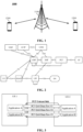
- FIG. 1 exemplarily illustrates a network device 1100 and two terminal devices 1200.
- a communication system 1000 may include multiple network devices 1100 and another number of terminal devices may be included in coverage of each network device 1100, which is not limited in the embodiment of the disclosure.
- the wireless communication system 1000 shown in FIG. 1 may further include other network entities such as a Mobility Management Entity (MME), and an Access and Mobility Management Function (AMF), which is not limited in the embodiment of the disclosure.
- MME Mobility Management Entity
- AMF Access and Mobility Management Function
- system and "network” may usually be exchanged herein.
- the term “and/or” herein describes an association relationship of associated objects and represents, for example, that three relationships may exist. For example, A and/or B may represent the following three cases: Only A exists, both A and B exist, and only B exists.
- the character “/” herein generally indicates that the contextual objects are in an "or” relationship.
- the term "correspondence” may mean that there is a direct correspondence or indirect correspondence between the two, or may mean that there is an association relationship between the two, or may mean a relationship between indicating and being indicated, or between configuring and being configured.
- FIG. 2 illustrates a 5G network system architecture in which the UE performs an access layer connection with an Access Network (AN) through a Uu wireless interface to realize access layer message interaction and wireless data transmission.
- the UE performs a None Access Stratum (NAS) connection with the AMF through an N1 interface to realize NAS message interaction.
- the AMF is a mobility management function in a core network
- a Session Management Function (SMF) is a session management function in the core network, and in addition to performing mobility management on the UE, the AMF is also responsible for forwarding session management related information between the UE and the SMF.
- a Policy Control Function PCF is a policy control function in the core network, and is responsible for formulating policies related to mobility management, session management, charging, etc.
- a User Plane Function is a user plane function in the core network, and performs data transmission with an external data network through an N6 interface and with the AN through an N3 interface.
- the UE accesses a 5G network through the Uu interface and then transmits service data through the network.
- a network layer of the UE When a service is initiated, a network layer of the UE obtains a QoS requirement of the service from an upper layer (such as an operating system or an application), and the UE converts the QoS requirement of the service into a QoS parameter of the Uu interface, for example, a 5G QoS Identifier (5QI), sends same to the network, and establishes a PDU session under the control of SMF for data transmission.
- the 5QI may be mapped to a series of QoS features such as a time delay, a bit error rate and a scheduling priority.
- the UE with ProSe capability may directly communicate with anotherUE with ProSe capability through a PC5 wireless interface.
- the two UEs respectively determine the QoS requirements corresponding to service data transmission according to the QoS requirement of the service, and establishes a PC5 QoS data flow which may guarantee the corresponding QoS requirement between the two UEs to transmit the service data, so as to guarantee the service quality of the service in PC5 communication.
- the QoS parameters of the PC5 QoS data flow include a PQI (PC5 5QI), and the PQI may be mapped to a series of QoS features such as a time delay, a bit error rate and a scheduling priority.
- PC5 5QI PC5 5QI
- the UE When one UE may be connected to the external data network through the 5G network and be ProSe capable, the UE may act as relay UE, and another remote UE with ProSe capability may establish a direct connection with the relay UE through the PC5 interface. Furthermore, the remote UE may interact with an N3IWF through a PDU session established by the relay UE and the 5G network. Referring to FIG. 4 , the remote UE may access a 5G core network serving the remote UE through the N3 IWF and communicate with the data network.
- a QoS parameter between the remote UE and the data network is controlled by the core network of the remote UE, and the N3IWF may obtain the QoS parameter for data interaction between the remote UE and the N3IWF from the core network (PCF) of the remote UE.
- PCF core network
- the data interaction between the remote UE and the N3IWF is transmitted through the PC5 interface between the remote UE and the relay UE and the PDU session established by the relay UE and the 5G network, if the QoS parameter of the PC5 interface or the QoS parameter of the PDU session of the relay UE may not be set correctly, a correct QoS guarantee may not be provided for the services between the remote UE and the data network, which will affect the service experience of the remote UE, and needs to be optimized.
- the embodiments of the disclosure provide a QoS control method, applied to a first terminal device.
- the first terminal device is used as remote UE, the first terminal device accesses a core network of the first terminal device through relay UE and a first designated network element, and the first terminal device is in communication connection with the relay UE through a first interface.
- the QoS control method includes the following operations.
- the first terminal device receives first information.
- the first terminal device determines traffic filtering information and QoS parameter information according to received first information.
- the first terminal device sends the traffic filtering information and the QoS parameter information to the relay UE for performing, by the relay UE, QoS control on the first interface and QoS control on a PDU session of the relay UE.
- the remote UE sends the QoS information about data interaction between the remote UE and the designated network element (such as an N3IWF) to the relay UE, and the relay UE performs QoS control on the first interface (such as a PC5 interface) and QoS control on the PDU session of the relay UE.
- the relay UE may correctly set the QoS parameter of the first interface and the QoS parameter of the PDU session of the relay UE, and based on this, the relay UE may provide a correct QoS guarantee for the services between the remote UE and the data network, so as to achieve the purpose of improving the service experience of the remote UE.
- the first information includes at least one of the following information sent by the first designated network element: a Security Parameter Index (SPI), a Differentiated Services Code Point (DSCP), or first QoS information.
- SPI Security Parameter Index
- DSCP Differentiated Services Code Point
- the first QoS information includes a first QoS identifier and/or code rate information.
- the first QoS information further includes time delay requirement information and/or bit error rate requirement information.
- the operation that the first terminal device determines the traffic filtering information and the QoS parameter information according to the received first information includes the following operations.
- the first information further includes: first mapping relationship information sent by a first core network element of the first terminal device, the first mapping relationship information including a mapping relationship from the DSCP to a second QoS identifier.
- the first terminal device determines the second QoS identifier according to the first mapping relationship information and a received DSCP.
- the operation that the first terminal device determines the traffic filtering information and the QoS parameter information according to the received first information includes the following operations.
- the QoS parameter information further includes the code rate information in the first QoS information.
- the first information further includes: second mapping relationship information sent by the first core network element of the first terminal device, the second mapping relationship information including a mapping relationship from a first QoS identifier to a second QoS identifier.
- the first terminal device determines the second QoS identifier according to the second mapping relationship information and the first QoS identifier in received first QoS information.
- the operation that the first terminal device determines the traffic filtering information and the QoS parameter information according to the received first information includes the following operations.
- the QoS parameter information further includes the code rate information in the first QoS information.
- the first QoS identifier includes a 5QI; and/or, the second QoS identifier includes a PQI.
- the first designated network element optionally comprises an N3IWF; and/or, the first interface includes a PC5 interface; and/or, the first core network element of the first terminal device includes a PCF of the first terminal device.
- the embodiments of the disclosure also provide a QoS control method, applied to relay UE.
- Remote UE accesses a core network of the remote UE through the relay UE and a first designated network element, and the remote UE is in communication connection with the relay UE through a first interface.
- the QoS control method includes the following operation.
- the relay UE receives traffic filtering information and QoS parameter information sent by the remote UE for performing, by the relay UE, QoS control on the first interface and QoS control on a PDU session of the relay UE.
- the traffic filtering information includes an SPI and/or a DSCP
- the QoS parameter information includes first QoS identifier information and/or code rate information
- the first QoS identifier includes a 5QI.
- the traffic filtering information includes an SPI and a DSCP
- the QoS parameter information includes a second QoS identifier
- the second QoS identifier includes a PQI.
- the QoS parameter information further includes code rate information.
- the first designated network element includes an N3IWF; and/or, the first interface includes a PC5 interface.
- the embodiments not being part of the invention also provide a QoS control method, applied to a first core network element.
- the first core network element serves remote UE, the remote UE accesses a core network of the remote UE through relay UE and a first designated network element, and the remote UE is in communication connection with the relay UE through a first interface.
- the QoS control method includes the following operation.
- the first core network element sends mapping relationship information to the remote UE, the mapping relationship information being used for the remote UE to determine QoS parameter information.
- the relay UE performs QoS control on the first interface and QoS control on a PDU session of the relay UE based on the QoS parameter information.
- the mapping relationship information includes a mapping relationship from a DSCP to a second QoS identifier for determining, by the remote UE, the second QoS identifier according to the mapping relationship information and a received DSCP.
- the DSCP is sent to the remote UE by the first designated network element.
- the mapping relationship information includes a mapping relationship from a first QoS identifier to the second QoS identifier for determining, by the remote UE, the second QoS identifier according to the mapping relationship information and a received first QoS identifier.
- the first QoS identifier is sent to the remote UE by the first designated network element.
- the first QoS identifier includes a 5QI; and/or, the second QoS identifier includes a PQI.
- the first designated network element includes an N3IWF; and/or, the first interface includes a PC5 interface; and/or, the first core network element includes a PCF of the remote UE.
- the embodiments of the disclosure provide a QoS control method, applied to a first network device.
- Remote UE accesses a core network of the remote UE through relay UE and a first designated network element, the remote UE is in communication connection with the relay UE through a first interface, and the first network device may include a core network element of the relay UE.
- the QoS control method includes the following operations.
- the first network device receives first information.
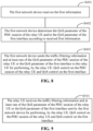
- the first network device determines a QoS parameter of a PDU session of the relay UE and/or a QoS parameter of the first interface according to the received first information.
- the first network device sends traffic filtering information and at least one of the QoS parameter of the PDU session of the relay UE or the QoS parameter of the first interface to the relay UE for performing, by the relay UE, QoS control on the PDU session of the relay UE and QoS control on the first interface.
- a designated network element such as an N3IWF
- the core network element such as a PCF serving the relay UE
- the PCF of the relay UE performs QoS control on the PDU session of the relay UE and QoS control on the first interface (such as a PC5 interface).
- the PCF of the relay UE may correctly set the QoS parameter of the PDU session of the relay UE and the QoS parameter of the first interface, and based on this, the PCF of the relay UE may provide a correct QoS guarantee for the services between the remote UE and the data network, so as to achieve the purpose of improving the service experience of the remote UE.
- the first information includes at least one of the following information sent by the first designated network element: an SPI, a DSCP, or first QoS information.
- the first QoS information includes a first QoS identifier and/or code rate information.
- the first QoS identifier includes a 5QI.
- the first QoS information further includes time delay requirement information and/or bit error rate requirement information.
- the operation that the first network device determines the QoS parameter of the PDU session of the relay UE and/or the QoS parameter of the first interface according to the received first information includes that: the first network device determines the QoS parameter of the PDU session of the relay UE and/or the QoS parameter of the first interface according to received first QoS information.
- the operation that the first network device determines the QoS parameter of the PDU session of the relay UE and/or the QoS parameter of the first interface according to the received first information includes that: the first network device determines the QoS parameter of the PDU session of the relay UE and/or the QoS parameter of the first interface according to a received DSCP.
- the traffic filtering information includes the SPI and the DSCP
- the first designated network element includes the N3IWF; and/or, the first interface includes the PC5 interface; and/or, the first network device includes the PCF of the relay UE.
- the embodiments not being part of the invention provide a QoS control method, applied to relay UE.
- Remote UE accesses a core network of the remote UE through the relay UE and a first designated network element, and the remote UE is in communication connection with the relay UE through a first interface.
- the QoS control method includes the following operation.
- the relay UE receives traffic filtering information and at least one of a QoS parameter of a PDU session of the relay UE or a QoS parameter of the first interface that are sent by the first network device for performing, by the relay UE, QoS control on the PDU session of the relay UE and QoS control on the first interface.
- the traffic filtering information includes an SPI and/or a DSCP.
- the first designated network element includes an N3IWF; and/or, the first interface includes a PC5 interface; and/or, the first network device includes a PCF of the relay UE.
- the remote UE takes the SPI and/or DSCP obtained from the N3IWF as the traffic filtering information and determines QoS information according to the information obtained from the N3IWDF, and the remote UE sends the traffic filtering information and the QoS information to the relay UE to perform QoS control; or, the N3IWF may directly send the SPI, DSCP and/or QoS information to the PCF of the relay UE for performing QoS control.
- the QoS parameter of the PDU session of the relay UE may be set correctly, and the QoS parameter of the PC5 interface may also be set correctly, so as to provide a correct QoS guarantee for the services between the remote UE and the data network, which is conductive to improving the service experience of the remote UE in various scenarios.
- the remote UE sends the QoS information about data interaction between the remote UE and the N3IWF to the relay UE, and the relay UE performs QoS control on the PC5 interface and QoS control on the PDU session of the relay UE.
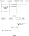
- FIG. 10 illustrates an information interaction process between each UE and each network element in the embodiment.
- the N3IWF sends the SPI, the DSCP and the first QoS information about data interaction between the remote UE and the N3IWF to the remote UE.
- the first QoS information includes a 5QI and a code rate.
- the first QoS information may further include QoS feature values such as time delay requirements and bit error rate requirements. Specifically, the remaining steps may be completed in the following cases.
- the remote UE takes the SPI and DSCP obtained in step 2 as the traffic filtering information, and provides the traffic filtering information and the first QoS information obtained in step 2 for the relay UE. Then, the relay UE performs QoS control on the PDU session of the relay UE and the PC5 interface according to the information obtained from remote UE.
- the PCF configures the mapping relationship from the DSCP to the PQI to the remote UE, and the remote UE determines the PQI from the DSCP obtained in step 2.
- the remote UE uses the SPI and DSCP obtained in step 2 as the traffic filtering information, and provides the traffic filtering information and the second QoS information for the relay UE, the second QoS information including the PQI determined by the remote UE according to the DSCP.
- the second QoS information further includes part of the information in the first QoS information obtained in step 2, such as code rate information.
- the relay UE performs QoS control on the PDU session of the relay UE and the PC5 interface according to the information obtained from remote UE.
- the PCF configures the mapping relationship from the 5QI to the PQI to the remote UE, and the remote UE determines the second QoS information according to the mapping relationship and the first QoS information obtained in step 2, for example, the 5QI in the first QoS information is mapped to the PQI, and the second QoS information may include other information in the first QoS information, such as code rate information.
- the remote UE uses the SPI and DSCP obtained in step 2 as the traffic filtering information, and provides the traffic filtering information and the second QoS information for the relay UE. Then, the relay UE performs QoS control on the PDU session of the relay UE and the PC5 interface according to the information obtained from the remote UE.
- the N3IWF sends the QoS information about data interaction between the remote UE and the N3IWF to the core network element (such as the PCF serving the relay UE) of the relay UE, and the PCF of the relay UE performs QoS control on the PDU session of the relay UE and/or QoS control on the PC5 interface.
- the core network element such as the PCF serving the relay UE
- the PCF of the relay UE performs QoS control on the PDU session of the relay UE and/or QoS control on the PC5 interface.
- FIG. 11 illustrates an information interaction process between each UE and each network element in the embodiment.
- the N3IWF sends the SPI, the DSCP and/or the first QoS information about data interaction between the remote UE and the N3IWF to the PCF of the remote UE.
- the first QoS information includes a 5QI and a code rate.
- the first QoS information may further include QoS feature values such as time delay requirements and bit error rate requirements. Specifically, the remaining steps may be completed in the following cases.
- the PCF of the relay UE determines the QoS parameter of the PDU session of the relay UE and/or the QoS parameter of the PC5 interface according to the first QoS information, and uses the SPI and the DSCP as the traffic filtering information, and the PCF sends the traffic filtering information and at least one of the QoS parameter of the PDU session of the relay UE or the QoS parameter of the PC5 interface to the relay UE through the SMF of the relay UE for performing QoS control.
- the PCF of the relay UE is included in an intermediate network illustrated in FIG. 11 .
- the PCF of the relay UE determines the QoS parameter of the PDU session of the relay UE and/or the QoS parameter of the PC5 interface according to the DSCP, and uses the SPI and the DSCP as the traffic filtering information, and the PCF sends the traffic filtering information and at least one of the QoS parameter of the PDU session of the relay UE or the QoS parameter of the PC5 interface to the relay UE through the SMF of the relay UE for performing QoS control.
- the PCF of the relay UE is included in the intermediate network illustrated in FIG. 11 .
- the QoS parameter of the PDU session of the relay UE may be correctly set, so as to provide a correct QoS guarantee for the services between the remote UE and the data network, thereby improving the service experience of the remote UE in a similar scenario by using the embodiments of the disclosure.
- the embodiments of the disclosure also provide a terminal device 100.
- the terminal device 100 accesses a core network of the terminal device through relay UE and a first designated network element, and the terminal device is in communication connection with the relay UE through a first interface.
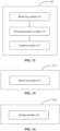
- the terminal device includes: a receiving module 110, a first determination module 120 and a sending module 130.
- the receiving module 110 is configured to receive first information.
- the first determination module 120 is configured to determine traffic filtering information and QoS parameter information according to received first information.
- the sending module 130 is configured to send the traffic filtering information and the QoS parameter information to the relay UE for performing, by the relay UE, QoS control on the first interface and QoS control on a PDU session of the relay UE.
- the first information includes at least one of the following information sent by the first designated network element: an SPI, a DSCP, or first QoS information.
- the first QoS information includes a first QoS identifier and/or code rate information.
- the first QoS information further includes time delay requirement information and/or bit error rate requirement information.
- the first determination module includes: a first determination submodule and a second determination sub-module.
- the first determination sub-module is configured to determine that the traffic filtering information includes the SPI and the DSCP.
- the second determination sub-module is configured to determine that the QoS parameter information includes the first QoS information.
- the first information further includes: first mapping relationship information sent by a first core network element of the terminal device, the first mapping relationship information including a mapping relationship from the DSCP to a second QoS identifier.
- the terminal device further includes a second determination module, configured to determine the second QoS identifier according to the first mapping relationship information and a received DSCP.
- the first determination module includes: a third determination submodule and a fourth determination sub-module.
- the third determination sub-module is configured to determine that the traffic filtering information includes the SPI and the DSCP.
- the fourth determination sub-module is configured to determine that the QoS parameter information includes the second QoS identifier determined according to the first mapping relationship information.
- the QoS parameter information further includes the code rate information in the first QoS information.
- the first information further includes: second mapping relationship information sent by the first core network element of the terminal device, the second mapping relationship information including a mapping relationship from a first QoS identifier to a second QoS identifier.
- the terminal device further includes a third determination module, configured to determine the second QoS identifier according to the second mapping relationship information and the first QoS identifier in received first QoS information.
- the first determination module includes: a fifth determination submodule and a sixth determination sub-module.
- the fifth determination sub-module is configured to determine that the traffic filtering information includes the SPI and the DSCP.
- the sixth determination sub-module is configured to determine that the QoS parameter information includes the second QoS identifier determined according to the second mapping relationship information.
- the QoS parameter information further includes the code rate information in the first QoS information.
- the first QoS identifier includes a 5QI; and/or, the second QoS identifier includes a PQI.
- the first designated network element includes an N3IWF; and/or, the first interface includes a PC5 interface; and/or, the first core network element of the terminal device includes a PCF of the terminal device.
- the embodiments of the disclosure also provide a terminal device 200.
- the terminal device is used as relay UE, remote UE accesses a core network of the remote UE through the terminal device and a first designated network element, and the remote UE is in communication connection with the terminal device through a first interface.
- the terminal device includes: a receiving module 210.
- the receiving module 210 is configured to receive traffic filtering information and QoS parameter information sent by the remote UE for performing, by the terminal device, QoS control on the first interface and QoS control on a PDU session of the relay UE.
- the traffic filtering information includes an SPI and a DSCP, and the QoS parameter information includes first QoS identifier information and/or code rate information.
- the first QoS identifier includes a 5QI.
- the traffic filtering information includes an SPI and a DSCP, and the QoS parameter information includes a second QoS identifier.
- the second QoS identifier includes a PQI.
- the QoS parameter information further includes code rate information.
- the first designated network element includes an N3IWF; and/or, the first interface includes a PC5 interface.
- the embodiments of the disclosure also provide a network device 300.
- the network device is used as a core network element, the network device serves remote UE, the remote UE accesses a core network of the remote UE through relay UE and a first designated network element, and the remote UE is in communication connection with the relay UE through a first interface.
- the network device 300 includes a sending module 310.
- the sending module 310 is configured to send mapping relationship information to the remote UE, the mapping relationship information being used for the remote UE to determine QoS parameter information. After the remote UE sends the QoS parameter information to the relay UE, the relay UE performs QoS control on the first interface and QoS control on a PDU session of the relay UE based on the QoS parameter information.
- the mapping relationship information includes a mapping relationship from a DSCP to a second QoS identifier for determining, by the remote UE, the second QoS identifier according to the mapping relationship information and a received DSCP.
- the DSCP is sent to the remote UE by the first designated network element.
- the mapping relationship information includes a mapping relationship from a first QoS identifier to the second QoS identifier for determining, by the remote UE, the second QoS identifier according to the mapping relationship information and a received first QoS identifier.
- the first QoS identifier is sent to the remote UE by the first designated network element.
- the first QoS identifier includes a 5QI; and/or, the second QoS identifier includes a PQI.
- the first designated network element includes an N3IWF; and/or, the first interface includes a PC5 interface; and/or, the network device includes a PCF of the remote UE.
- the embodiments of the disclosure also provide a network device 400.
- the network device is used as a core network element of relay UE, remote UE accesses a core network of the remote UE through the relay UE and a first designated network element, the remote UE is in communication connection with the relay UE through a first interface.
- the network device 400 includes: a receiving module 410, a determination module 420 and a sending module 430.
- the receiving module 410 is configured to receive first information.
- the determination module 420 is configured to determine a QoS parameter of a PDU session of the relay UE and/or a QoS parameter of the first interface according to the received first information.
- the sending module 430 is configured to send traffic filtering information and at least one of the QoS parameter of the PDU session of the relay UE or the QoS parameter of the first interface to the relay UE for performing, by the relay UE, QoS control on the PDU session of the relay UE and QoS control on the first interface.
- the first information includes at least one of the following information sent by the first designated network element: an SPI, a DSCP, or first QoS information.
- the first QoS information includes a first QoS identifier and/or code rate information.
- the first QoS identifier includes a 5QI.
- the first QoS information further includes time delay requirement information and/or bit error rate requirement information.
- the determination module includes a first determination submodule, configured to determine the QoS parameter of the PDU session of the relay UE and/or the QoS parameter of the first interface according to received first QoS information.
- the determination module includes a second determination submodule, configured to determine QoS parameter of the PDU session of the relay UE and/or the QoS parameter of the first interface according to a received DSCP.
- the traffic filtering information includes an SPI and a DSCP.
- the first designated network element includes an N3IWF; and/or, the first interface includes a PC5 interface; and/or, the network device includes a PCF of the relay UE.
- the embodiments of the disclosure also provide a terminal device 500.
- the terminal device is used as relay UE, remote UE accesses a core network of the remote UE through the terminal device and a first designated network element, and the remote UE is in communication connection with the terminal device through a first interface.
- the terminal device 500 includes: a receiving module 510.
- the receiving module 510 is configured to receive traffic filtering information and at least one of a QoS parameter of a PDU session of the terminal device or a QoS parameter of the first interface that are sent by the first network device for performing, by the terminal device, QoS control on the PDU session of the terminal device and QoS control on the first interface.
- the traffic filtering information includes an SPI and a DSCP.
- the first designated network element includes an N3IWF; and/or, the first interface includes a PC5 interface; and/or, the first network device includes a PCF of the terminal device.
- the terminal devices 100, 200 and 500 and the network devices 300 and 400 in the embodiment of the disclosure may realize the corresponding functions of the terminal device in the method embodiment.
- the process, function, implementation mode, and beneficial effect corresponding to each module (submodule, unit, component, or the like) in the terminal devices 100, 200 and 500 and the network devices 300 and 400 may refer to the corresponding descriptions in the method embodiment, and will not be elaborated herein.
- each module (submodule, unit, component, or the like) in the terminal devices 100, 200 and 500 and the network devices 300 and 400 of the embodiment of the disclosure may be realized by different modules (submodules, units, components, or the like), or by the same module (submodule, unit, component or the like).
- the first sending module and the second sending module may be different modules or may be the same module, both of which can realize the corresponding function of the terminal device in the embodiments of the disclosure.
- FIG. 17 is a schematic structural diagram of a communication device 600 according to an embodiment of the disclosure.
- the communication device 600 includes a processor 610, and the processor 610 may call and run a computer program from a memory to implement the method in the embodiments of the disclosure.
- the communication device 600 may further include a memory 620.
- the processor 610 may call and run the computer program from the memory 620 to implement the method in the embodiments of the present disclosure.
- the memory 620 may be a separate device independent of the processor 610 or integrated in the processor 610.
- the communication device 600 may further include a transceiver 630, and the processor 610 may control the transceiver 630 to communicate with other devices. Specifically, same may send information or data to or receive information or data sent by other devices.
- the transceiver 630 may include a transmitter and a receiver.
- the transceiver 630 may further include an antenna, and the number of antennas may be one or more.
- the communication device 600 may be the network device of the embodiments of the disclosure.
- the communication device 600 may implement corresponding flows implemented by the network device in each method of the embodiments of the disclosure. For brevity, elaborations are omitted herein.
- the communication device 600 may be the terminal device of the embodiments of the disclosure.
- the communication device 600 may implement corresponding flows implemented by the terminal device in each method of the embodiments of the disclosure. For brevity, elaborations are omitted herein.
- FIG. 18 is a schematic structural diagram of a chip 700 according to an embodiment not being part of the invention.
- the chip 700 includes a processor 710, and the processor 710 may call and run a computer program from a memory to implement the method in the embodiments of the disclosure.
- the chip 700 may further include a memory 720.
- the processor 710 may call and run the computer program from the memory 720 to implement the method in the embodiments of the present disclosure.
- the memory 720 may be a separate device independent of the processor 710 or integrated in the processor 710.
- the chip 700 may further include an input interface 730.
- the processor 710 may control the input interface 730 to communicate with other devices or chips, and specifically, may acquire information or data sent by other devices or chips.
- the chip 700 may further include an output interface 740.
- the processor 710 may control the output interface 740 to communicate with other devices or chips, and specifically, may output information or data to other devices or chips.
- the chip may be applied to the network device of the embodiments of the disclosure.
- the chip may implement corresponding flows implemented by the network device in each method of the embodiments of the disclosure. For brevity, elaborations are omitted herein.
- the chip may be applied to the terminal device of the embodiment in FIG. 12 or FIG. 13 of the disclosure.
- the chip may implement corresponding flows implemented by the terminal device in each method of the embodiments of the disclosure. For brevity, elaborations are omitted herein.
- the chip mentioned in the embodiments not being part of the invention may also be called a system-level chip, a system chip, a chip system, a system on chip, or the like.
- the processor mentioned above may be a general-purpose processor, a Digital Signal Processor (DSP), a Field Programmable Gate Array (FPGA), an Application Specific Integrated Circuit (ASIC), or another programmable logical device, transistor logical device, discrete hardware component, etc.
- DSP Digital Signal Processor
- FPGA Field Programmable Gate Array
- ASIC Application Specific Integrated Circuit
- the general-purpose processor mentioned above may be a microprocessor, or any conventional processor, etc.
- the memory mentioned above may be a volatile memory or a nonvolatile memory, or may include both volatile and nonvolatile memories.
- the nonvolatile memory may be a Read-Only Memory (ROM), a Programmable ROM (PROM), an Erasable PROM (EPROM), an Electrically EPROM (EEPROM), or a flash memory.
- the volatile memory may be a Random Access Memory (RAM).
- the memory in the embodiments of the disclosure may also be a Static RAM (SRAM), a Dynamic RAM (DRAM), a Synchronous DRAM (SDRAM), a Double Data Rate SDRAM (DDR SDRAM), an Enhanced SDRAM (ESDRAM), a Synch Link DRAM (SLDRAM), and a Direct Rambus RAM (DR RAM). That is, the memory in the embodiments of the disclosure is intended to include, but not limited to, memories of these and any other proper types.
- SRAM Static RAM
- DRAM Dynamic RAM
- SDRAM Synchronous DRAM
- DDR SDRAM Double Data Rate SDRAM
- ESDRAM Enhanced SDRAM
- SLDRAM Synch Link DRAM
- DR RAM Direct Rambus RAM
- FIG. 19 is a schematic block diagram of a communication system 800 according to the disclosure.
- the communication system 800 includes a terminal device 810 and a network device 820.
- the terminal device 810 may be configured to realize the corresponding functions realized by the terminal device in the method of various embodiments of the disclosure
- the network device 820 may be configured to realize the corresponding functions realized by the network device in the method of various embodiments of the disclosure.
- the embodiments may be implemented completely or partially through software, hardware, firmware or any combination thereof.
- the embodiments may be implemented completely or partially in form of a computer program product.
- the computer program product includes one or more computer instructions.
- the computer may be a universal computer, a dedicated computer, a computer network, or another programmable device.
- the computer instruction may be stored in a computer readable storage medium or transmitted from a computer readable storage medium to another computer readable storage medium.
- the computer instruction may be transmitted from a website, computer, server, or data center to another website, computer, server, or data center in a wired (such as coaxial cable, optical fiber, and Digital Subscriber Line (DSL)) or wireless (such as infrared, radio, and microwave) manner.
- the computer readable storage medium may be any available medium accessible for the computer or a data storage device integrated with one or more available media, such as a server and a data center.
- the available medium may be a magnetic medium (for example, a floppy disk, a hard disk and a magnetic tape), an optical medium (for example, a Digital Video Disk (DVD)), a semiconductor medium (for example, a Solid State Disk (SSD)), or the like.
- sequence numbers of the foregoing processes do not mean execution sequences in various embodiments of the disclosure.
- the execution sequences of the processes should be determined according to functions and internal logics of the processes, and should not be construed as any limitation to the implementation processes of the embodiments of the disclosure.
Landscapes
- Engineering & Computer Science (AREA)
- Computer Networks & Wireless Communication (AREA)
- Signal Processing (AREA)
- Quality & Reliability (AREA)
- Mobile Radio Communication Systems (AREA)
Claims (14)
- Procédé de contrôle de la qualité de service, notée QoS, appliqué à un premier dispositif terminal, le premier dispositif terminal accédant à un réseau cœur du premier dispositif terminal au travers d'un équipement utilisateur, noté UE, de relais et d'un premier élément de réseau désigné, le premier dispositif terminal étant en connexion de communication avec l'UE de relais au travers d'une première interface,
le procédé de contrôle de la QoS comprenant :la réception (S101), par le premier dispositif terminal, de premières informations,la détermination (S102), par le premier dispositif terminal, d'informations sur le filtrage du trafic et d'informations sur des paramètres de QoS selon les premières informations reçues ; etl'envoi (S103), par le premier dispositif terminal, des informations sur le filtrage du trafic et des informations sur des paramètres de QoS à l'UE de relais,caractérisé en ce que la détermination, par le premier dispositif terminal, des informations sur le filtrage du trafic selon les premières informations reçues comprend :
la détermination, par le premier dispositif terminal, que les informations sur le filtrage du trafic comprennent un indice de paramètres de sécurité, noté SPI, et un point de code de services différenciés, noté DSCP. - Procédé selon la revendication 2, dans lequel
les premières informations comprennent au moins un élément dans le groupe d'informations suivantes reçues par le premier élément de réseau désigné : le DSCP, ou des premières informations sur la QoS. - Procédé selon la revendication 2, dans lequel les premières informations sur la QoS comprennent un premier identifiant de QoS et/ou des informations sur un débit de code.
- Procédé selon la revendication 3, dans lequel
le premier identifiant de QoS comprend un identifiant de QoS de 5e Génération, notée 5G, noté 5QI. - Procédé selon l'une quelconque des revendications 1 à 4, dans lequelle premier élément de réseau désigné comprenant une fonction d'interfonctionnement non-3GPP, notée N3IWF ; et/ou,la première interface comprend une interface PC5.
- Procédé de contrôle de la qualité de service, notée QoS, appliqué à un équipement utilisateur, noté UE, de relais, un UE distant accédant à un réseau cœur de l'UE distant au travers de l'UE de relais et d'un premier élément de réseau désigné, l'UE distant étant en connexion de communication avec l'UE de relais au travers d'une première interface,
le procédé de contrôle de la QoS comprenant :la réception (201), par l'UE de relais, d'informations sur le filtrage du trafic et d'informations sur des paramètres de QoS envoyées par l'UE distant en vue de la réalisation, par l'UE de relais, d'un contrôle de la QoS sur la première interface et d'un contrôle de la QoS sur une session d'unités de données de protocole, notées PDU, de l'UE de relais,caractérisé en ce que les informations sur le filtrage du trafic comprennent un indice de paramètres de sécurité, noté SPI, et un point de code de services différenciés, noté DSCP. - Procédé selon la revendication 6, dans lequel
les informations sur des paramètres de QoS comprennent un deuxième identifiant de QoS. - Procédé selon la revendication 7, dans lequel le deuxième identifiant de QoS comprend un 5QI PC5, noté PQI.
- Procédé selon l'une quelconque des revendications 6 à 8, dans lequelle premier élément de réseau désigné comprend une fonction d'interfonctionnement non-3GPP, notée N3IWF ; et/ou,la première interface comprend une interface PC5.
- Procédé de contrôle de la qualité de service, notée QoS, appliqué à un premier dispositif de réseau, un équipement utilisateur, noté UE, distant accédant à un réseau cœur de l'UE distant au travers d'un UE de relais et d'un premier élément de réseau désigné, l'UE distant étant en connexion de communication avec l'UE de relais au travers d'une première interface, et le premier dispositif de réseau comprenant un élément de réseau cœur de l'UE de relais,
le procédé de contrôle de la QoS comprenant :la réception (S401), par le premier dispositif de réseau, de premières informations,la détermination (S402), par le premier dispositif de réseau, d'un paramètre de QoS d'une session d'unités de données de protocole, notées PDU, de l'UE de relais et/ou d'un paramètre de QoS de la première interface selon les premières informations reçues ; etl'envoi (S403) à l'UE de relais, par le premier dispositif de réseau, d'informations sur le filtrage du trafic et d'au moins un paramètre parmi le paramètre de QoS de la session PDU de l'UE de relais et le paramètre de QoS de la première interface,caractérisé en ce que les informations sur le filtrage du trafic comprennent un indice de paramètres de sécurité, noté SPI, et un point de code de services différenciés, noté DSCP. - Procédé selon la revendication 10, dans lequel
les premières informations comprennent au moins un élément dans le groupe d'informations suivantes reçues par le premier élément de réseau désigné : le DSCP, ou des premières informations sur la QoS. - Dispositif terminal, comprenant un processeur et une mémoire, la mémoire étant configurée pour stocker un programme d'ordinateur, et le processeur appelant et exécutant le programme d'ordinateur stocké dans la mémoire pour réaliser le procédé selon l'une quelconque des revendications 1 à 9.
- Dispositif de réseau, comprenant un processeur et une mémoire, la mémoire étant configurée pour stocker un programme d'ordinateur, et le processeur appelant et exécutant le programme d'ordinateur stocké dans la mémoire pour réaliser le procédé selon l'une quelconque des revendications 10 à 11.
- Support de stockage lisible par ordinateur, configuré pour stocker un programme d'ordinateur,
le programme d'ordinateur permettant à un ordinateur de réaliser le procédé selon l'une quelconque des revendications 1 à 11.
Applications Claiming Priority (1)
| Application Number | Priority Date | Filing Date | Title |
|---|---|---|---|
| PCT/CN2020/139258 WO2022133977A1 (fr) | 2020-12-25 | 2020-12-25 | Procédé de contrôle de qualité de service (qos), dispositif terminal, et dispositif de réseau |
Publications (3)
| Publication Number | Publication Date |
|---|---|
| EP4271037A1 EP4271037A1 (fr) | 2023-11-01 |
| EP4271037A4 EP4271037A4 (fr) | 2024-01-10 |
| EP4271037B1 true EP4271037B1 (fr) | 2025-04-23 |
Family
ID=82158621
Family Applications (1)
| Application Number | Title | Priority Date | Filing Date |
|---|---|---|---|
| EP20966543.9A Active EP4271037B1 (fr) | 2020-12-25 | 2020-12-25 | Procédé de contrôle de qualité de service (qos), dispositif terminal, et dispositif de réseau |
Country Status (4)
| Country | Link |
|---|---|
| US (1) | US12425915B2 (fr) |
| EP (1) | EP4271037B1 (fr) |
| CN (1) | CN115699867A (fr) |
| WO (1) | WO2022133977A1 (fr) |
Families Citing this family (1)
| Publication number | Priority date | Publication date | Assignee | Title |
|---|---|---|---|---|
| CN120935666A (zh) * | 2024-05-09 | 2025-11-11 | 华为技术有限公司 | 服务质量配置方法及通信装置 |
Citations (1)
| Publication number | Priority date | Publication date | Assignee | Title |
|---|---|---|---|---|
| WO2020177764A1 (fr) * | 2019-03-06 | 2020-09-10 | 维沃移动通信有限公司 | Procédé de garantie de transmission de données et dispositif de communication |
Family Cites Families (18)
| Publication number | Priority date | Publication date | Assignee | Title |
|---|---|---|---|---|
| WO2015021649A1 (fr) * | 2013-08-16 | 2015-02-19 | 华为技术有限公司 | Procédé et dispositif de transmission de données |
| US9985799B2 (en) | 2014-09-05 | 2018-05-29 | Alcatel-Lucent Usa Inc. | Collaborative software-defined networking (SDN) based virtual private network (VPN) |
| WO2017028294A1 (fr) | 2015-08-20 | 2017-02-23 | 华为技术有限公司 | Procédé et appareil de traitement de données |
| US10439682B2 (en) * | 2016-08-19 | 2019-10-08 | FG Innovation Company Limited | Access mechanism for proximity-based service UE-to-network relay service |
| CN108366355B (zh) * | 2017-01-26 | 2023-05-02 | 中兴通讯股份有限公司 | 数据发送方法、数据发送终端以及基站 |
| CN110035018B (zh) * | 2018-01-12 | 2021-08-13 | 华为技术有限公司 | 确定网络服务质量流的方法、网元和系统 |
| US12143852B2 (en) * | 2019-02-21 | 2024-11-12 | Ipla Holdings Inc. | Meeting strict QoS requirements through network control of device route and location |
| CN120074617A (zh) * | 2019-05-01 | 2025-05-30 | 交互数字专利控股公司 | 用于5g网络中的多跳中继的方法 |
| EP4021047B1 (fr) * | 2019-08-19 | 2026-03-25 | LG Electronics Inc. | Authentification pour relais |
| CN114586468B (zh) * | 2019-08-22 | 2025-02-11 | Lg电子株式会社 | 中继ue的针对远端ue的操作方法 |
| WO2021040423A1 (fr) * | 2019-08-27 | 2021-03-04 | 엘지전자 주식회사 | Communication liée à une mise à jour de configuration |
| WO2021040463A1 (fr) * | 2019-08-29 | 2021-03-04 | 엘지전자 주식회사 | Communication relative à un état de désactivation du service de données ps 3gpp |
| CN115769635A (zh) * | 2020-05-19 | 2023-03-07 | 交互数字专利控股公司 | 用于远程ue连接的侧行链路适配协议 |
| CN114173384B (zh) * | 2020-09-10 | 2025-02-11 | 大唐移动通信设备有限公司 | QoS控制方法、装置及处理器可读存储介质 |
| KR102736339B1 (ko) * | 2020-11-16 | 2024-11-29 | 아서스테크 컴퓨터 인코포레이션 | 무선 통신 시스템에서 uu 무선 베어러 대 pc5 무선 링크 제어(rlc) 베어러 매핑을 위한 방법 및 장치 |
| US12207330B2 (en) * | 2021-09-09 | 2025-01-21 | Asustek Computer Inc. | Method and apparatus for supporting multiple connectivity services in a wireless communication system |
| CN117395710B (zh) * | 2022-07-11 | 2024-05-14 | 华硕技术授权股份有限公司 | 无线通信系统中用于服务质量流建立的方法和设备 |
| US20230015829A1 (en) * | 2022-09-14 | 2023-01-19 | Intel Corporation | Apparatus, system, method and computer-implemented storage media to implement a per data packet quality of service requirement in a communication network |
-
2020
- 2020-12-25 EP EP20966543.9A patent/EP4271037B1/fr active Active
- 2020-12-25 WO PCT/CN2020/139258 patent/WO2022133977A1/fr not_active Ceased
- 2020-12-25 CN CN202080101951.1A patent/CN115699867A/zh active Pending
-
2022
- 2022-12-22 US US18/145,473 patent/US12425915B2/en active Active
Patent Citations (2)
| Publication number | Priority date | Publication date | Assignee | Title |
|---|---|---|---|---|
| WO2020177764A1 (fr) * | 2019-03-06 | 2020-09-10 | 维沃移动通信有限公司 | Procédé de garantie de transmission de données et dispositif de communication |
| EP3937540A1 (fr) * | 2019-03-06 | 2022-01-12 | Vivo Mobile Communication Co., Ltd. | Procédé de garantie de transmission de données et dispositif de communication |
Also Published As
| Publication number | Publication date |
|---|---|
| EP4271037A1 (fr) | 2023-11-01 |
| WO2022133977A1 (fr) | 2022-06-30 |
| EP4271037A4 (fr) | 2024-01-10 |
| US12425915B2 (en) | 2025-09-23 |
| US20230224754A1 (en) | 2023-07-13 |
| CN115699867A (zh) | 2023-02-03 |
Similar Documents
| Publication | Publication Date | Title |
|---|---|---|
| WO2023115545A1 (fr) | Procédé de transmission d'informations, premier dispositif de réseau d'accès, second dispositif de réseau d'accès et terminal | |
| US20240236655A1 (en) | Information indication method, first access network device, and core network element | |
| CN116321489A (zh) | 中继发现方法和终端 | |
| US11924893B2 (en) | Method for establishing connection, and terminal device | |
| US12425946B2 (en) | Terminal device and network device | |
| US12356225B2 (en) | Method for service identification and terminal device | |
| US12425915B2 (en) | Quality of service (QoS) control method, terminal device, and network device | |
| US20250211981A1 (en) | Communication method and device | |
| CN116602046A (zh) | 发现方法和终端 | |
| CN116491176A (zh) | 无线通信的方法、终端设备和网络设备 | |
| CN115348627B (zh) | 切片信息配置方法和设备 | |
| CN116325832B (zh) | 会话管理方法、终端设备和网络设备 | |
| EP4142370B1 (fr) | Communication de relais | |
| CN115669166B (zh) | 检测控制信息的方法、传输控制信息的方法、终端设备和网络设备 | |
| EP4716305A1 (fr) | Procédé de communication relais, équipement terminal et dispositif de réseau | |
| US20250343749A1 (en) | Communication method and device | |
| WO2023150998A1 (fr) | Procédé de communication sans fil, dispositif terminal et dispositif de réseau | |
| CN120917778A (zh) | 通信方法和设备 | |
| WO2026030841A1 (fr) | Procédé de communication pour liaison de relais à sauts multiples, terminal et dispositif réseau | |
| WO2025118161A1 (fr) | Procédé et dispositif de communication | |
| WO2023184405A1 (fr) | Procédé de communication sans fil, dispositif de réseau et dispositif terminal | |
| WO2023070671A1 (fr) | Procédé de traitement de service restreint, dispositif terminal et dispositif de réseau | |
| CN121569514A (zh) | 感知上报确定方法、终端设备和网络设备 | |
| CN120858592A (zh) | 通信方法和设备 |
Legal Events
| Date | Code | Title | Description |
|---|---|---|---|
| STAA | Information on the status of an ep patent application or granted ep patent |
Free format text: STATUS: THE INTERNATIONAL PUBLICATION HAS BEEN MADE |
|
| PUAI | Public reference made under article 153(3) epc to a published international application that has entered the european phase |
Free format text: ORIGINAL CODE: 0009012 |
|
| STAA | Information on the status of an ep patent application or granted ep patent |
Free format text: STATUS: REQUEST FOR EXAMINATION WAS MADE |
|
| 17P | Request for examination filed |
Effective date: 20221221 |
|
| AK | Designated contracting states |
Kind code of ref document: A1 Designated state(s): AL AT BE BG CH CY CZ DE DK EE ES FI FR GB GR HR HU IE IS IT LI LT LU LV MC MK MT NL NO PL PT RO RS SE SI SK SM TR |
|
| REG | Reference to a national code |
Ref country code: DE Ref legal event code: R079 Free format text: PREVIOUS MAIN CLASS: H04W0028160000 Ipc: H04W0028240000 Ref country code: DE Ref legal event code: R079 Ref document number: 602020050232 Country of ref document: DE Free format text: PREVIOUS MAIN CLASS: H04W0028160000 Ipc: H04W0028240000 |
|
| A4 | Supplementary search report drawn up and despatched |
Effective date: 20231211 |
|
| RIC1 | Information provided on ipc code assigned before grant |
Ipc: H04W 88/04 20090101ALN20231205BHEP Ipc: H04W 28/02 20090101ALI20231205BHEP Ipc: H04W 28/24 20090101AFI20231205BHEP |
|
| DAV | Request for validation of the european patent (deleted) | ||
| DAX | Request for extension of the european patent (deleted) | ||
| STAA | Information on the status of an ep patent application or granted ep patent |
Free format text: STATUS: EXAMINATION IS IN PROGRESS |
|
| 17Q | First examination report despatched |
Effective date: 20240710 |
|
| GRAP | Despatch of communication of intention to grant a patent |
Free format text: ORIGINAL CODE: EPIDOSNIGR1 |
|
| STAA | Information on the status of an ep patent application or granted ep patent |
Free format text: STATUS: GRANT OF PATENT IS INTENDED |
|
| RIC1 | Information provided on ipc code assigned before grant |
Ipc: H04W 88/04 20090101ALN20250120BHEP Ipc: H04W 28/02 20090101ALI20250120BHEP Ipc: H04W 28/24 20090101AFI20250120BHEP |
|
| INTG | Intention to grant announced |
Effective date: 20250129 |
|
| GRAS | Grant fee paid |
Free format text: ORIGINAL CODE: EPIDOSNIGR3 |
|
| GRAA | (expected) grant |
Free format text: ORIGINAL CODE: 0009210 |
|
| STAA | Information on the status of an ep patent application or granted ep patent |
Free format text: STATUS: THE PATENT HAS BEEN GRANTED |
|
| AK | Designated contracting states |
Kind code of ref document: B1 Designated state(s): AL AT BE BG CH CY CZ DE DK EE ES FI FR GB GR HR HU IE IS IT LI LT LU LV MC MK MT NL NO PL PT RO RS SE SI SK SM TR |
|
| REG | Reference to a national code |
Ref country code: GB Ref legal event code: FG4D |
|
| REG | Reference to a national code |
Ref country code: CH Ref legal event code: EP |
|
| REG | Reference to a national code |
Ref country code: DE Ref legal event code: R096 Ref document number: 602020050232 Country of ref document: DE |
|
| REG | Reference to a national code |
Ref country code: IE Ref legal event code: FG4D |
|
| REG | Reference to a national code |
Ref country code: NL Ref legal event code: MP Effective date: 20250423 |
|
| PG25 | Lapsed in a contracting state [announced via postgrant information from national office to epo] |
Ref country code: NL Free format text: LAPSE BECAUSE OF FAILURE TO SUBMIT A TRANSLATION OF THE DESCRIPTION OR TO PAY THE FEE WITHIN THE PRESCRIBED TIME-LIMIT Effective date: 20250423 |
|
| REG | Reference to a national code |
Ref country code: AT Ref legal event code: MK05 Ref document number: 1789029 Country of ref document: AT Kind code of ref document: T Effective date: 20250423 |
|
| P01 | Opt-out of the competence of the unified patent court (upc) registered |
Free format text: CASE NUMBER: UPC_APP_5329_4271037/2025 Effective date: 20250829 |
|
| PG25 | Lapsed in a contracting state [announced via postgrant information from national office to epo] |
Ref country code: FI Free format text: LAPSE BECAUSE OF FAILURE TO SUBMIT A TRANSLATION OF THE DESCRIPTION OR TO PAY THE FEE WITHIN THE PRESCRIBED TIME-LIMIT Effective date: 20250423 Ref country code: ES Free format text: LAPSE BECAUSE OF FAILURE TO SUBMIT A TRANSLATION OF THE DESCRIPTION OR TO PAY THE FEE WITHIN THE PRESCRIBED TIME-LIMIT Effective date: 20250423 Ref country code: PT Free format text: LAPSE BECAUSE OF FAILURE TO SUBMIT A TRANSLATION OF THE DESCRIPTION OR TO PAY THE FEE WITHIN THE PRESCRIBED TIME-LIMIT Effective date: 20250825 |
|
| REG | Reference to a national code |
Ref country code: LT Ref legal event code: MG9D |
|
| PG25 | Lapsed in a contracting state [announced via postgrant information from national office to epo] |
Ref country code: GR Free format text: LAPSE BECAUSE OF FAILURE TO SUBMIT A TRANSLATION OF THE DESCRIPTION OR TO PAY THE FEE WITHIN THE PRESCRIBED TIME-LIMIT Effective date: 20250724 Ref country code: NO Free format text: LAPSE BECAUSE OF FAILURE TO SUBMIT A TRANSLATION OF THE DESCRIPTION OR TO PAY THE FEE WITHIN THE PRESCRIBED TIME-LIMIT Effective date: 20250723 |
|
| PG25 | Lapsed in a contracting state [announced via postgrant information from national office to epo] |
Ref country code: PL Free format text: LAPSE BECAUSE OF FAILURE TO SUBMIT A TRANSLATION OF THE DESCRIPTION OR TO PAY THE FEE WITHIN THE PRESCRIBED TIME-LIMIT Effective date: 20250423 |
|
| PG25 | Lapsed in a contracting state [announced via postgrant information from national office to epo] |
Ref country code: BG Free format text: LAPSE BECAUSE OF FAILURE TO SUBMIT A TRANSLATION OF THE DESCRIPTION OR TO PAY THE FEE WITHIN THE PRESCRIBED TIME-LIMIT Effective date: 20250423 |
|
| PG25 | Lapsed in a contracting state [announced via postgrant information from national office to epo] |
Ref country code: HR Free format text: LAPSE BECAUSE OF FAILURE TO SUBMIT A TRANSLATION OF THE DESCRIPTION OR TO PAY THE FEE WITHIN THE PRESCRIBED TIME-LIMIT Effective date: 20250423 |
|
| PG25 | Lapsed in a contracting state [announced via postgrant information from national office to epo] |
Ref country code: AT Free format text: LAPSE BECAUSE OF FAILURE TO SUBMIT A TRANSLATION OF THE DESCRIPTION OR TO PAY THE FEE WITHIN THE PRESCRIBED TIME-LIMIT Effective date: 20250423 |
|
| PG25 | Lapsed in a contracting state [announced via postgrant information from national office to epo] |
Ref country code: RS Free format text: LAPSE BECAUSE OF FAILURE TO SUBMIT A TRANSLATION OF THE DESCRIPTION OR TO PAY THE FEE WITHIN THE PRESCRIBED TIME-LIMIT Effective date: 20250723 |
|
| PG25 | Lapsed in a contracting state [announced via postgrant information from national office to epo] |
Ref country code: IS Free format text: LAPSE BECAUSE OF FAILURE TO SUBMIT A TRANSLATION OF THE DESCRIPTION OR TO PAY THE FEE WITHIN THE PRESCRIBED TIME-LIMIT Effective date: 20250823 |
|
| PG25 | Lapsed in a contracting state [announced via postgrant information from national office to epo] |
Ref country code: LV Free format text: LAPSE BECAUSE OF FAILURE TO SUBMIT A TRANSLATION OF THE DESCRIPTION OR TO PAY THE FEE WITHIN THE PRESCRIBED TIME-LIMIT Effective date: 20250423 |
|
| PGFP | Annual fee paid to national office [announced via postgrant information from national office to epo] |
Ref country code: DE Payment date: 20251212 Year of fee payment: 6 |
|
| PGFP | Annual fee paid to national office [announced via postgrant information from national office to epo] |
Ref country code: GB Payment date: 20251211 Year of fee payment: 6 |
|
| PG25 | Lapsed in a contracting state [announced via postgrant information from national office to epo] |
Ref country code: DK Free format text: LAPSE BECAUSE OF FAILURE TO SUBMIT A TRANSLATION OF THE DESCRIPTION OR TO PAY THE FEE WITHIN THE PRESCRIBED TIME-LIMIT Effective date: 20250423 Ref country code: SM Free format text: LAPSE BECAUSE OF FAILURE TO SUBMIT A TRANSLATION OF THE DESCRIPTION OR TO PAY THE FEE WITHIN THE PRESCRIBED TIME-LIMIT Effective date: 20250423 |
|
| PG25 | Lapsed in a contracting state [announced via postgrant information from national office to epo] |
Ref country code: CZ Free format text: LAPSE BECAUSE OF FAILURE TO SUBMIT A TRANSLATION OF THE DESCRIPTION OR TO PAY THE FEE WITHIN THE PRESCRIBED TIME-LIMIT Effective date: 20250423 |
|
| PG25 | Lapsed in a contracting state [announced via postgrant information from national office to epo] |
Ref country code: EE Free format text: LAPSE BECAUSE OF FAILURE TO SUBMIT A TRANSLATION OF THE DESCRIPTION OR TO PAY THE FEE WITHIN THE PRESCRIBED TIME-LIMIT Effective date: 20250423 |
|
| REG | Reference to a national code |
Ref country code: DE Ref legal event code: R097 Ref document number: 602020050232 Country of ref document: DE |
|
| PG25 | Lapsed in a contracting state [announced via postgrant information from national office to epo] |
Ref country code: SK Free format text: LAPSE BECAUSE OF FAILURE TO SUBMIT A TRANSLATION OF THE DESCRIPTION OR TO PAY THE FEE WITHIN THE PRESCRIBED TIME-LIMIT Effective date: 20250423 |
|
| PG25 | Lapsed in a contracting state [announced via postgrant information from national office to epo] |
Ref country code: IT Free format text: LAPSE BECAUSE OF FAILURE TO SUBMIT A TRANSLATION OF THE DESCRIPTION OR TO PAY THE FEE WITHIN THE PRESCRIBED TIME-LIMIT Effective date: 20250423 |
|
| PLBE | No opposition filed within time limit |
Free format text: ORIGINAL CODE: 0009261 |
|
| STAA | Information on the status of an ep patent application or granted ep patent |
Free format text: STATUS: NO OPPOSITION FILED WITHIN TIME LIMIT |
|
| REG | Reference to a national code |
Ref country code: CH Ref legal event code: L10 Free format text: ST27 STATUS EVENT CODE: U-0-0-L10-L00 (AS PROVIDED BY THE NATIONAL OFFICE) Effective date: 20260304 |
|
| PG25 | Lapsed in a contracting state [announced via postgrant information from national office to epo] |
Ref country code: RO Free format text: LAPSE BECAUSE OF FAILURE TO SUBMIT A TRANSLATION OF THE DESCRIPTION OR TO PAY THE FEE WITHIN THE PRESCRIBED TIME-LIMIT Effective date: 20250423 |
|
| 26N | No opposition filed |
Effective date: 20260126 |