EP4272601A1 - Möbelanordnung mit klappbett, klapptisch und drehklapptisch - Google Patents
Möbelanordnung mit klappbett, klapptisch und drehklapptisch Download PDFInfo
- Publication number
- EP4272601A1 EP4272601A1 EP23166489.7A EP23166489A EP4272601A1 EP 4272601 A1 EP4272601 A1 EP 4272601A1 EP 23166489 A EP23166489 A EP 23166489A EP 4272601 A1 EP4272601 A1 EP 4272601A1
- Authority
- EP
- European Patent Office
- Prior art keywords
- folding
- horizontal
- rotation
- vertical
- table top
- Prior art date
- Legal status (The legal status is an assumption and is not a legal conclusion. Google has not performed a legal analysis and makes no representation as to the accuracy of the status listed.)
- Withdrawn
Links
- 230000009466 transformation Effects 0.000 description 2
- 101100390736 Danio rerio fign gene Proteins 0.000 description 1
- 101100390738 Mus musculus Fign gene Proteins 0.000 description 1
Images
Classifications
-
- A—HUMAN NECESSITIES
- A47—FURNITURE; DOMESTIC ARTICLES OR APPLIANCES; COFFEE MILLS; SPICE MILLS; SUCTION CLEANERS IN GENERAL
- A47C—CHAIRS; SOFAS; BEDS
- A47C19/00—Bedsteads
- A47C19/22—Combinations of bedsteads with other furniture or with accessories, e.g. with bedside cabinets
-
- A—HUMAN NECESSITIES
- A47—FURNITURE; DOMESTIC ARTICLES OR APPLIANCES; COFFEE MILLS; SPICE MILLS; SUCTION CLEANERS IN GENERAL
- A47B—TABLES; DESKS; OFFICE FURNITURE; CABINETS; DRAWERS; GENERAL DETAILS OF FURNITURE
- A47B3/00—Folding or stowable tables
-
- A—HUMAN NECESSITIES
- A47—FURNITURE; DOMESTIC ARTICLES OR APPLIANCES; COFFEE MILLS; SPICE MILLS; SUCTION CLEANERS IN GENERAL
- A47B—TABLES; DESKS; OFFICE FURNITURE; CABINETS; DRAWERS; GENERAL DETAILS OF FURNITURE
- A47B5/00—Suspended or hinged panels forming a table; Wall tables
- A47B5/04—Suspended or hinged panels forming a table; Wall tables foldable
-
- A—HUMAN NECESSITIES
- A47—FURNITURE; DOMESTIC ARTICLES OR APPLIANCES; COFFEE MILLS; SPICE MILLS; SUCTION CLEANERS IN GENERAL
- A47B—TABLES; DESKS; OFFICE FURNITURE; CABINETS; DRAWERS; GENERAL DETAILS OF FURNITURE
- A47B83/00—Combinations comprising two or more pieces of furniture of different kinds
- A47B83/04—Tables combined with other pieces of furniture
-
- A—HUMAN NECESSITIES
- A47—FURNITURE; DOMESTIC ARTICLES OR APPLIANCES; COFFEE MILLS; SPICE MILLS; SUCTION CLEANERS IN GENERAL
- A47C—CHAIRS; SOFAS; BEDS
- A47C17/00—Sofas; Couches; Beds
- A47C17/52—Cabinet beds; Table beds, or like beds; Wardrobe beds
- A47C17/62—Table beds; Billiard table beds, or like beds
-
- A—HUMAN NECESSITIES
- A47—FURNITURE; DOMESTIC ARTICLES OR APPLIANCES; COFFEE MILLS; SPICE MILLS; SUCTION CLEANERS IN GENERAL
- A47B—TABLES; DESKS; OFFICE FURNITURE; CABINETS; DRAWERS; GENERAL DETAILS OF FURNITURE
- A47B9/00—Tables with tops of variable height
Definitions
- Furniture arrangements with a folding bed and with a folding table and/or a folding turntable are basically known.
- the present invention is based on the object of providing a furniture arrangement that is as space-saving as possible.
- first floor surface at least partially overlaps with the second and/or with the third floor surface.
- the folding bed on the one hand and the folding table and/or the folding turntable on the other hand cannot be folded down into their horizontal lying and working positions at the same time, but only alternately. In this way, the available floor space is optimally utilized.
- the folding bed on the one hand and the folding table and/or the folding turntable on the other hand are arranged on two opposite or on two adjacent room walls.
- the folding turntable has a swivel arm which is rotatably mounted about the vertical axis of rotation, in particular through 90 °, between the basic position accommodated in the furniture body and an end position extended from the furniture body, with the at least one table top on the swivel arm about the horizontal axis of rotation between one is foldable in the vertical starting position and the horizontal working position.
- the swivel arm can be attached to a vertical rotating column that is attached to a building is rotatably mounted about the vertical axis of rotation by means of a lower and an upper pivot bearing.
- a table top is mounted on both sides of the swivel arm so that it can be folded about a horizontal axis of rotation between the vertical basic position and the horizontal end position, in order to optionally form a rotary folding table in the form of a single table with a single horizontal table top - or a double table with two horizontal table tops.
- the folding table and/or the folding turntable can advantageously be designed to be vertically movable.
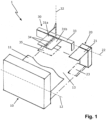
- Furniture arrangement 1 shown includes a folding bed 10, a height-adjustable folding table 20 and a folding turntable 30.
- the folding bed 10 has a bed surface 11, shown broken here, which is mounted so that it can be folded down from a vertical storage position about a horizontal axis of rotation 12 into a horizontal lying position. In its folded-down, horizontal lying position shown, the bed surface 11 covers a first floor surface 13.
- the folding table 20 has a table top 21, which is mounted so that it can be folded up from a vertical basic position about a horizontal axis of rotation 22 into a horizontal working position. In its folded-up, horizontal working position shown, the table top 21 covers a second floor surface 23.
- the folding turntable 30 has at least one table top, here two table tops 31a, 31b, which can be rotated from a vertical basic position about a vertical axis of rotation 32 out of a furniture body (here sideboard) 33 and are each mounted so that they can be folded up about a horizontal axis of rotation 34 into a horizontal working position. In their unscrewed, folded-up horizontal working position shown, the two table tops 31a, 32b cover a third floor surface 35.
- the first floor surface 13 partially overlaps with the second and third floor surfaces 23, 35, so that the folding bed 10 on the one hand and the folding table 20 and the folding turntable 30 on the other hand are not folded down into their horizontal lying and working positions at the same time, but only alternately can. In this way, the available floor space is optimally utilized.
- the folding bed 10 on the one hand and the folding table 20 and the folding turntable 30 on the other hand are arranged on two opposing room walls.
- the folding turntable 30 has a swivel arm 36 which is rotatably mounted about the vertical axis of rotation 32, in particular through 90 °, between a basic position accommodated in the furniture body 33 and an end position extended from the furniture body 33.
- the two table tops 31a, 31b are mounted on both sides of the swivel arm 36 so that they can be folded up about a horizontal axis of rotation 34 between a vertical starting position and a horizontal end position.
- the swivel arm 36 is attached to a vertical rotating column 37 , which is rotatably mounted about the vertical axis of rotation 32 - for example by means of a lower pivot bearing 38 on the building floor and an upper pivot bearing 39 on the building ceiling.
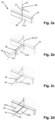
- Fig. 2a the furniture body 33 is closed by the folded-down table top 31a.
- This table top 31a thus forms the front panel and the other table top 31b forms a back panel of the furniture body 33.
- the horizontal swivel arm 36 is attached to the rotating column 37, on which the table top 31a is mounted on either side only on one side about the horizontal axis of rotation 34 by means of folding fittings or, as shown, on both sides the two table tops 31a, 31b are mounted so that they can be folded up about the horizontal axes of rotation 34 .
- the swivel arm 36 is rotated forward by 90° from the furniture body 33 by means of the rotating column 37 about the vertical axis of rotation 32 and locked.
- Fig. 2c one table top 31b is folded upwards by 90° about the horizontal axis of rotation 34 on the swivel arm 36 and fixed in order to form a rotary folding table in the form of a single table with a horizontal table top.
- Fig. 2d the other table top 31a on the swivel arm 36 is folded upwards by 90 ° about the horizontal axis of rotation 34 and fixed in order to form a rotary folding table in the form of a double table with two horizontal table tops.
- the swivel arm 36 can also be turned out forwards about the vertical axis of rotation 32 with the table top 31a already folded up by means of the rotating column 37. If desired, the other table top 31b can then be folded up and locked in place so that the in Fig. 2d to form the double table shown.
Landscapes
- Health & Medical Sciences (AREA)
- General Health & Medical Sciences (AREA)
- Nursing (AREA)
- Tables And Desks Characterized By Structural Shape (AREA)
Abstract
Eine Möbelanordnung (1) umfasst
- ein Klappbett (10) mit einer Bettfläche (11), die aus einer vertikalen Verstaustellung um eine horizontale Drehachse (12) in eine horizontale Liegestellung aufklappbar gelagert ist, wobei die Bettfläche (11) in ihrer aufgeklappten, horizontalen Liegestellung eine erste Bodenfläche (13) überdeckt, und
- einen Klapptisch (20) mit einer Tischplatte (21), die aus einer vertikalen Grundstellung um eine horizontale Drehachse (22) aufklappbar in eine horizontale Arbeitsstellung gelagert ist, wobei die Tischplatte (21) in ihrer aufgeklappten, horizontalen Arbeitsstellung eine zweite Bodenfläche (23) überdeckt, und/oder einen Klappdrehtisch (30) mit mindestens einer Tischplatte (31a, 31b), die aus einer vertikalen Grundstellung um eine vertikale Drehachse (32) aus einem Möbelkorpus (33) heraus drehbar und um eine horizontale Drehachse (34) aufklappbar in eine horizontale Arbeitsstellung gelagert ist, wobei die mindestens eine Tischplatte (31a, 31b) in ihrer herausgedrehten, horizontalen Arbeitsstellung eine dritte Bodenfläche (35) überdeckt,
- ein Klappbett (10) mit einer Bettfläche (11), die aus einer vertikalen Verstaustellung um eine horizontale Drehachse (12) in eine horizontale Liegestellung aufklappbar gelagert ist, wobei die Bettfläche (11) in ihrer aufgeklappten, horizontalen Liegestellung eine erste Bodenfläche (13) überdeckt, und
- einen Klapptisch (20) mit einer Tischplatte (21), die aus einer vertikalen Grundstellung um eine horizontale Drehachse (22) aufklappbar in eine horizontale Arbeitsstellung gelagert ist, wobei die Tischplatte (21) in ihrer aufgeklappten, horizontalen Arbeitsstellung eine zweite Bodenfläche (23) überdeckt, und/oder einen Klappdrehtisch (30) mit mindestens einer Tischplatte (31a, 31b), die aus einer vertikalen Grundstellung um eine vertikale Drehachse (32) aus einem Möbelkorpus (33) heraus drehbar und um eine horizontale Drehachse (34) aufklappbar in eine horizontale Arbeitsstellung gelagert ist, wobei die mindestens eine Tischplatte (31a, 31b) in ihrer herausgedrehten, horizontalen Arbeitsstellung eine dritte Bodenfläche (35) überdeckt,
Erfindungsgemäß überlappt die erste Bodenfläche (13) zumindest teilweise mit der zweiten und/oder mit der dritten Bodenfläche (23, 35).
Description
- Die Erfindung betrifft eine Möbelanordnung, aufweisend
- ein Klappbett mit einer Bettfläche, die aus einer vertikalen Verstaustellung um eine horizontale Drehachse in eine horizontale Liegestellung aufklappbar gelagert ist, wobei die Bettfläche in ihrer aufgeklappten, horizontalen Liegestellung eine erste Bodenfläche überdeckt, und
- einen Klapptisch mit einer Tischplatte, die aus einer vertikalen Grundstellung um eine horizontale Drehachse aufklappbar in eine horizontale Arbeitsstellung gelagert ist, wobei die Tischplatte in ihrer aufgeklappten, horizontalen Arbeitsstellung eine zweite Bodenfläche überdeckt, und/oder einen Klappdrehtisch mit mindestens einer Tischplatte, die aus einer vertikalen Grundstellung um eine vertikale Drehachse aus einem Möbelkorpus heraus drehbar und um eine horizontale Drehachse aufklappbar in eine horizontale Arbeitsstellung gelagert ist, wobei die mindestens eine Tischplatte in ihrer herausgedrehten, horizontalen Arbeitsstellung eine dritte Bodenfläche überdeckt.
- Möbelanordnungen mit einem Klappbett und mit einem Klapptisch und/oder einem Klappdrehtisch sind grundsätzlich bekannt.
- Demgegenüber liegt der vorliegenden Erfindung die Aufgabe zugrunde, eine möglichst platzsparende Möbelanordnung anzugeben.
- Diese Aufgabe wird erfindungsgemäß dadurch gelöst, dass die erste Bodenfläche zumindest teilweise mit der zweiten und/oder mit der dritten Bodenfläche überlappt.
- Erfindungsgemäß können das Klappbett einerseits und der Klapptisch und/oder der Klappdrehtisch andererseits nicht zeitgleich, sondern nur abwechselnd in ihre horizontalen Liege- und Arbeitsstellungen heruntergeklappt werden. Auf diese Weise wird die vorhandene Bodenfläche optimal ausgenutzt.
- Vorzugsweise sind das Klappbett einerseits und der Klapptisch und/oder der Klappdrehtisch andererseits an zwei einander gegenüberliegenden oder an zwei benachbarten Raumwänden angeordnet.
- Besonders bevorzugt weist der Klappdrehtisch einen Schwenkarm auf, der um die vertikale Drehachse, insbesondere um 90°, zwischen der im Möbelkorpus aufgenommenen Grundstellung und einer aus dem Möbelkorpus ausgefahrenen Endstellung drehbar gelagert ist, wobei die mindestens eine Tischplatte am Schwenkarm um die horizontale Drehachse zwischen einer vertikalen Ausgangsstellung und der horizontalen Arbeitsstellung klappbar gelagert ist. Dabei kann der Schwenkarm an einer vertikalen Drehsäule befestigt sein, die an einem Gebäude um die vertikale Drehachse mittels eines unteren und eines oberen Drehlagers drehbar gelagert ist. Weiter bevorzugt ist am Schwenkarm beidseitig jeweils eine Tischplatte um eine horizontale Drehachse zwischen der vertikalen Grundstellung und der horizontalen Endstellung klappbar gelagert, um so wahlweise einen Drehklapptisch in Form eines Einzeltisches mit einer einzigen horizontalen Tischplatte - oder eines Doppeltischs mit zwei horizontalen Tischplatten auszubilden.
- Vorteilhaft können der Klapptisch und/oder der Klappdrehtisch höhenverfahrbar ausgebildet sein.
- Weitere Vorteile der Erfindung ergeben sich aus der Beschreibung, den Ansprüchen und der Zeichnung. Ebenso können die vorstehenden genannten und die noch weiter aufgeführten Merkmale je für sich oder zu mehreren in beliebigen Kombinationen Verwendung finden. Die gezeigten und beschriebenen Ausführungsformen sind nicht als abschließende Aufzählung zu verstehen, sondern haben vielmehr beispielhaften Charakter für die Schilderung der Erfindung.
- Es zeigen:
- Fig. 1
- die erfindungsgemäße Möbelanordnung mit einem Klappbett, einem Klapptisch und einem Klappdrehtisch; und
- Fign. 2a-2d
- die Transformation des Drehklapptisches von einem Sideboard (
Fig. 2a ) zu einem Einzeltisch (Fig. 2c ) oder zu einem Doppeltisch (Fig. 2d ). - Die in
Fig. 1 gezeigte Möbelanordnung 1 umfasst ein Klappbett 10, einen höhenverfahrbaren Klapptisch 20 und einen Klappdrehtisch 30. - Das Klappbett 10 hat eine hier abgebrochen dargestellte Bettfläche 11, die aus einer vertikalen Verstaustellung um eine horizontale Drehachse 12 in eine horizontale Liegestellung herunterklappbar gelagert ist. In ihrer gezeigten heruntergeklappten, horizontalen Liegestellung überdeckt die Bettfläche 11 eine erste Bodenfläche 13.
- Der Klapptisch 20 hat eine Tischplatte 21, die aus einer vertikalen Grundstellung um eine horizontale Drehachse 22 in eine horizontale Arbeitsstellung hochklappbar gelagert ist. In ihrer gezeigten hochgeklappten, horizontalen Arbeitsstellung überdeckt die Tischplatte 21 eine zweite Bodenfläche 23.
- Der Klappdrehtisch 30 hat mindestens eine Tischplatte, hier zwei Tischplatte 31a, 31b, die aus einer vertikalen Grundstellung um eine vertikale Drehachse 32 aus einem Möbelkorpus (hier Sideboard) 33 heraus drehbar und jeweils um eine horizontale Drehachse 34 in eine horizontale Arbeitsstellung hochklappbar gelagert sind. In ihrer gezeigten herausgedrehten, hochgeklappten horizontalen Arbeitsstellung überdecken die beiden Tischplatten 31a, 32b eine dritte Bodenfläche 35.
- Wie in
Fig. 1 gezeigt, überlappt die erste Bodenfläche 13 teilweise mit der zweiten und mit der dritten Bodenfläche 23, 35, so dass das Klappbett 10 einerseits und der Klapptisch 20 und der Klappdrehtisch 30 andererseits nicht zeitgleich, sondern nur abwechselnd in ihre horizontalen Liege- und Arbeitsstellungen heruntergeklappt werden können. Auf diese Weise wird die vorhandene Bodenfläche optimal ausgenutzt. - Im gezeigten Ausführungsbeispiel sind das Klappbett 10 einerseits und der Klapptisch 20 und der Klappdrehtisch 30 andererseits an zwei einander gegenüberliegenden Raumwänden angeordnet.
- Wie in
Fign. 2a-2d gezeigt, weist der Klappdrehtisch 30 einen Schwenkarm 36 auf, der um die vertikale Drehachse 32, insbesondere um 90°, zwischen einer im Möbelkorpus 33 aufgenommenen Grundstellung und einer aus dem Möbelkorpus 33 ausgefahrenen Endstellung drehbar gelagert ist. Die beiden Tischplatten 31a, 31b sind beidseitig am Schwenkarm 36 jeweils um eine horizontale Drehachse 34 zwischen einer vertikalen Ausgangsstellung und einer horizontalen Endstellung hochklappbar gelagert. Der Schwenkarm 36 ist an einer vertikalen Drehsäule 37 befestigt ist, die - z.B. mittels eines unteren Drehlagers 38 am Gebäudeboden und eines oberen Drehlagers 39 an der Gebäusedecke - um die vertikale Drehachse 32 drehbar gelagert ist. - In
Fig. 2a ist der Möbelkorpus 33 durch die eine heruntergeklappte Tischplatte 31a geschlossen. Diese Tischplatte 31a bildet somit die Frontplatte und die andere Tischplatte 31b eine Rückplatte des Möbelkorpus 33. - Wie in
Fig. 2b gezeigt, ist an der Drehsäule 37 der horizontale Schwenkarm 36 befestigt, an dem jeweils mittels Klappbeschlägen entweder nur einseitig die Tischplatte 31a um die horizontale Drehachse 34 oder, wie dargestellt, beidseitig die beiden Tischplatten 31a, 31b jeweils um die horizontale Drehachsen 34 hochklappbar gelagert sind. InFig. 2b ist der Schwenkarm 36 mittels der Drehsäule 37 um die vertikale Drehachse 32 um 90° nach vorne aus dem Möbelkorpus 33 herausgedreht und festgestellt. - In
Fig. 2c ist die eine Tischplatte 31b am Schwenkarm 36 um die horizontale Drehachse 34 um 90° nach oben geklappt und festgestellt, um so einen Drehklapptisch in Form eines Einzeltischs mit einer horizontalen Tischplatte auszubilden. - In
Fig. 2d ist zusätzlich auch die andere Tischplatte 31a am Schwenkarm 36 um die horizontale Drehachse 34 um 90° nach oben geklappt und festgestellt, um so einen Drehklapptisch in Form eines Doppeltischs mit zwei horizontalen Tischplatten auszubilden. - Statt, wie in
Fig. 2b dargestellt, den Schwenkarm 36 mit heruntergeklappten Tischplatten 31a, 31b aus dem Möbelkorpus 33 herauszudrehen, kann der Schwenkarm 36 auch mit bereits hochgeklappter Tischplatte 31a mittels der Drehsäule 37 um die vertikale Drehachse 32 nach vorne herausgedreht werden. Falls gewünscht, kann anschließend die andere Tischplatte 31b hochgeklappt und festgestellt werden, um so den inFig. 2d gezeigten Doppeltisch auszubilden.
Claims (5)
- Möbelanordnung (1) aufweisend- ein Klappbett (10) mit einer Bettfläche (11), die aus einer vertikalen Verstaustellung um eine horizontale Drehachse (12) in eine horizontale Liegestellung aufklappbar gelagert ist, wobei die Bettfläche (11) in ihrer aufgeklappten, horizontalen Liegestellung eine erste Bodenfläche (13) überdeckt, und- einen Klapptisch (20) mit einer Tischplatte (21), die aus einer vertikalen Grundstellung um eine horizontale Drehachse (22) aufklappbar in eine horizontale Arbeitsstellung gelagert ist, wobei die Tischplatte (21) in ihrer aufgeklappten, horizontalen Arbeitsstellung eine zweite Bodenfläche (23) überdeckt, und/oder einen Klappdrehtisch (30) mit mindestens einer Tischplatte (31a, 31b), die aus einer vertikalen Grundstellung um eine vertikale Drehachse (32) aus einem Möbelkorpus (33) heraus drehbar und um eine horizontale Drehachse (34) aufklappbar in eine horizontale Arbeitsstellung gelagert ist, wobei die mindestens eine Tischplatte (31a, 31b) in ihrer herausgedrehten, horizontalen Arbeitsstellung eine dritte Bodenfläche (35) überdeckt,dadurch gekennzeichnet,
dass die erste Bodenfläche (13) zumindest teilweise mit der zweiten und/oder mit der dritten Bodenfläche (23, 35) überlappt. - Möbelanordnung nach Anspruch 1, dadurch gekennzeichnet, dass das Klappbett (10) einerseits und der Klapptisch (20) und/oder der Klappdrehtisch (30) andererseits an zwei einander gegenüberliegenden oder an zwei benachbarten Raumwänden angeordnet sind.
- Möbelanordnung nach Anspruch 1 oder 2, dadurch gekennzeichnet, dass der Klappdrehtisch (30) einen Schwenkarm (36), der um die vertikale Drehachse (32), insbesondere um 90°, zwischen der im Möbelkorpus (33) aufgenommenen Grundstellung und einer aus dem Möbelkorpus (33) ausgefahrenen Endstellung drehbar gelagert ist, wobei die mindestens eine Tischplatte (31a, 31b) am Schwenkarm (36) um die horizontale Drehachse (34) zwischen einer vertikalen Ausgangsstellung und der horizontalen Arbeitsstellung hochklappbar gelagert ist.
- Möbelanordnung nach Anspruch 3, dadurch gekennzeichnet, dass der Schwenkarm (36) an einer vertikalen Drehsäule (37) befestigt ist, die um die vertikale Drehachse (32) mittels eines unteren und eines oberen Drehlagers (38, 39) drehbar gelagert ist.
- Möbelanordnung nach einem der vorhergehenden Ansprüche, dadurch gekennzeichnet, dass der Klapptisch (20) und/oder der Klappdrehtisch (30) höhenverfahrbar ausgebildet sind.
Applications Claiming Priority (1)
| Application Number | Priority Date | Filing Date | Title |
|---|---|---|---|
| DE202022102372.7U DE202022102372U1 (de) | 2022-05-02 | 2022-05-02 | Möbelanordnung mit Klappbett, Klapptisch und Drehklapptisch |
Publications (1)
| Publication Number | Publication Date |
|---|---|
| EP4272601A1 true EP4272601A1 (de) | 2023-11-08 |
Family
ID=81749749
Family Applications (1)
| Application Number | Title | Priority Date | Filing Date |
|---|---|---|---|
| EP23166489.7A Withdrawn EP4272601A1 (de) | 2022-05-02 | 2023-04-04 | Möbelanordnung mit klappbett, klapptisch und drehklapptisch |
Country Status (2)
| Country | Link |
|---|---|
| EP (1) | EP4272601A1 (de) |
| DE (1) | DE202022102372U1 (de) |
Citations (7)
| Publication number | Priority date | Publication date | Assignee | Title |
|---|---|---|---|---|
| US2456037A (en) * | 1947-06-12 | 1948-12-14 | Webster F Woods | Folding dinette table |
| JPS5433208U (de) * | 1977-08-05 | 1979-03-05 | ||
| US5775034A (en) * | 1996-06-10 | 1998-07-07 | Logue; Michael F. D. | Folding screen environment system |
| JP2004248936A (ja) * | 2003-02-21 | 2004-09-09 | Osamu Fukushima | 可動式家具 |
| JP2010007288A (ja) * | 2008-06-25 | 2010-01-14 | Sugita Ace Kk | 空間構成体 |
| US20140202361A1 (en) * | 2012-10-18 | 2014-07-24 | Voytek Siwiec | Side Supported Foldable Panel Arrangement |
| KR102169818B1 (ko) * | 2019-12-17 | 2020-10-26 | 주식회사분도이엔지 | 다용도 시스템 가구 |
-
2022
- 2022-05-02 DE DE202022102372.7U patent/DE202022102372U1/de active Active
-
2023
- 2023-04-04 EP EP23166489.7A patent/EP4272601A1/de not_active Withdrawn
Patent Citations (7)
| Publication number | Priority date | Publication date | Assignee | Title |
|---|---|---|---|---|
| US2456037A (en) * | 1947-06-12 | 1948-12-14 | Webster F Woods | Folding dinette table |
| JPS5433208U (de) * | 1977-08-05 | 1979-03-05 | ||
| US5775034A (en) * | 1996-06-10 | 1998-07-07 | Logue; Michael F. D. | Folding screen environment system |
| JP2004248936A (ja) * | 2003-02-21 | 2004-09-09 | Osamu Fukushima | 可動式家具 |
| JP2010007288A (ja) * | 2008-06-25 | 2010-01-14 | Sugita Ace Kk | 空間構成体 |
| US20140202361A1 (en) * | 2012-10-18 | 2014-07-24 | Voytek Siwiec | Side Supported Foldable Panel Arrangement |
| KR102169818B1 (ko) * | 2019-12-17 | 2020-10-26 | 주식회사분도이엔지 | 다용도 시스템 가구 |
Also Published As
| Publication number | Publication date |
|---|---|
| DE202022102372U1 (de) | 2022-05-06 |
Similar Documents
| Publication | Publication Date | Title |
|---|---|---|
| DE4423402C2 (de) | Stützsäule zur Halterung einer Patientenlagerfläche | |
| DE102019109866A1 (de) | Möbelelement | |
| DE102013223486A1 (de) | Operationstisch | |
| DE212019000096U1 (de) | Zelt mit einem bequemen Verriegelungsmechanismus für Teleskopbeinrohre | |
| EP3586674B1 (de) | Tischplatteneinheit mit klappeinlage für einen ausziehbaren tisch | |
| DE202021002287U1 (de) | Faltbare Rahmenkonstruktion für mobile Theken mit innenliegender Arbeitsfläche, integriertem Fixierungsmechanismus und textiler Hüllkonstruktion | |
| DE202022102372U1 (de) | Möbelanordnung mit Klappbett, Klapptisch und Drehklapptisch | |
| DE212024000335U1 (de) | Schwenkbares elektrisches Trittbrett sowie Fahrzeug | |
| DE202008013987U1 (de) | Tischmöbel mit Kabelkanalvorrichtung | |
| DE2848826A1 (de) | Auseinanderfaltbare vorrichtung zum vergroessern von fahrzeugen | |
| DE2020145A1 (de) | Tisch mit einer hoehenverstellbaren Arbeitsplatte | |
| EP3993669B1 (de) | Möbel mit einem verdrehbaren, keilförmigen bett | |
| DE202022102371U1 (de) | Multifunktionsmöbel mit Drehklapptisch | |
| DE8533632U1 (de) | Markise | |
| DE19826463C2 (de) | Tisch mit verschwenkbarer Ergänzungsplatte | |
| DE9200754U1 (de) | Vorrichtung zum Aus- und Einfahren einer Dichtleiste an einem beweglichen Trennwandelement | |
| WO2020164897A1 (de) | Schrank mit ausziehbarem tablar | |
| EP4258939B1 (de) | Hebe-senk-auszugsvorrichtung und möbel oder haushaltsgerät | |
| EP1800640A1 (de) | Ausstellbare Trittstufe eines Fahrzeugs | |
| DE102024001984A1 (de) | Wandsystem und Raumanordnung | |
| DE19824734B4 (de) | Liege für ein Fahrzeug nach Art eines Campingfahrzeugs | |
| DE3835717A1 (de) | Arbeitstisch mit verstellbarer tischplatte | |
| DE20218455U1 (de) | Tischbeschlag aus Alu-Druckguß zur Vergrößerung eines Tisches vor Kopf | |
| DE202005018707U1 (de) | Markise, insbesondere Gelenkarmmarkise | |
| EP3563009B1 (de) | Wandschirmverbindungseinrichtung zum gelenkigen verbinden von wandschirmen und wandschirmanordnung |
Legal Events
| Date | Code | Title | Description |
|---|---|---|---|
| PUAI | Public reference made under article 153(3) epc to a published international application that has entered the european phase |
Free format text: ORIGINAL CODE: 0009012 |
|
| STAA | Information on the status of an ep patent application or granted ep patent |
Free format text: STATUS: THE APPLICATION HAS BEEN PUBLISHED |
|
| AK | Designated contracting states |
Kind code of ref document: A1 Designated state(s): AL AT BE BG CH CY CZ DE DK EE ES FI FR GB GR HR HU IE IS IT LI LT LU LV MC ME MK MT NL NO PL PT RO RS SE SI SK SM TR |
|
| STAA | Information on the status of an ep patent application or granted ep patent |
Free format text: STATUS: THE APPLICATION IS DEEMED TO BE WITHDRAWN |
|
| 18D | Application deemed to be withdrawn |
Effective date: 20240509 |