EP4272627B1 - Dispositif médical de surveillance des paramètres de santé d'un patient et procédé de surveillance des paramètres de santé d'un patient - Google Patents
Dispositif médical de surveillance des paramètres de santé d'un patient et procédé de surveillance des paramètres de santé d'un patient Download PDFInfo
- Publication number
- EP4272627B1 EP4272627B1 EP22171553.5A EP22171553A EP4272627B1 EP 4272627 B1 EP4272627 B1 EP 4272627B1 EP 22171553 A EP22171553 A EP 22171553A EP 4272627 B1 EP4272627 B1 EP 4272627B1
- Authority
- EP
- European Patent Office
- Prior art keywords
- sensor module
- main unit
- sensors
- patient
- function
- Prior art date
- Legal status (The legal status is an assumption and is not a legal conclusion. Google has not performed a legal analysis and makes no representation as to the accuracy of the status listed.)
- Active
Links
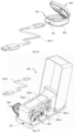
Images













Classifications
-
- A—HUMAN NECESSITIES
- A61—MEDICAL OR VETERINARY SCIENCE; HYGIENE
- A61B—DIAGNOSIS; SURGERY; IDENTIFICATION
- A61B5/00—Measuring for diagnostic purposes; Identification of persons
- A61B5/02—Detecting, measuring or recording for evaluating the cardiovascular system, e.g. pulse, heart rate, blood pressure or blood flow
- A61B5/0205—Simultaneously evaluating both cardiovascular conditions and different types of body conditions, e.g. heart and respiratory condition
- A61B5/02055—Simultaneously evaluating both cardiovascular condition and temperature
-
- A—HUMAN NECESSITIES
- A61—MEDICAL OR VETERINARY SCIENCE; HYGIENE
- A61B—DIAGNOSIS; SURGERY; IDENTIFICATION
- A61B5/00—Measuring for diagnostic purposes; Identification of persons
- A61B5/0002—Remote monitoring of patients using telemetry, e.g. transmission of vital signals via a communication network
-
- A—HUMAN NECESSITIES
- A61—MEDICAL OR VETERINARY SCIENCE; HYGIENE
- A61B—DIAGNOSIS; SURGERY; IDENTIFICATION
- A61B5/00—Measuring for diagnostic purposes; Identification of persons
- A61B5/117—Identification of persons
- A61B5/1171—Identification of persons based on the shapes or appearances of their bodies or parts thereof
- A61B5/1172—Identification of persons based on the shapes or appearances of their bodies or parts thereof using fingerprinting
-
- A—HUMAN NECESSITIES
- A61—MEDICAL OR VETERINARY SCIENCE; HYGIENE
- A61B—DIAGNOSIS; SURGERY; IDENTIFICATION
- A61B5/00—Measuring for diagnostic purposes; Identification of persons
- A61B5/24—Detecting, measuring or recording bioelectric or biomagnetic signals of the body or parts thereof
- A61B5/30—Input circuits therefor
- A61B5/307—Input circuits therefor specially adapted for particular uses
- A61B5/308—Input circuits therefor specially adapted for particular uses for electrocardiography [ECG]
-
- A—HUMAN NECESSITIES
- A61—MEDICAL OR VETERINARY SCIENCE; HYGIENE
- A61B—DIAGNOSIS; SURGERY; IDENTIFICATION
- A61B5/00—Measuring for diagnostic purposes; Identification of persons
- A61B5/24—Detecting, measuring or recording bioelectric or biomagnetic signals of the body or parts thereof
- A61B5/316—Modalities, i.e. specific diagnostic methods
- A61B5/318—Heart-related electrical modalities, e.g. electrocardiography [ECG]
-
- A—HUMAN NECESSITIES
- A61—MEDICAL OR VETERINARY SCIENCE; HYGIENE
- A61B—DIAGNOSIS; SURGERY; IDENTIFICATION
- A61B5/00—Measuring for diagnostic purposes; Identification of persons
- A61B5/68—Arrangements of detecting, measuring or recording means, e.g. sensors, in relation to patient
- A61B5/6801—Arrangements of detecting, measuring or recording means, e.g. sensors, in relation to patient specially adapted to be attached to or worn on the body surface
- A61B5/6813—Specially adapted to be attached to a specific body part
- A61B5/6823—Trunk, e.g., chest, back, abdomen, hip
-
- A—HUMAN NECESSITIES
- A61—MEDICAL OR VETERINARY SCIENCE; HYGIENE
- A61B—DIAGNOSIS; SURGERY; IDENTIFICATION
- A61B5/00—Measuring for diagnostic purposes; Identification of persons
- A61B5/68—Arrangements of detecting, measuring or recording means, e.g. sensors, in relation to patient
- A61B5/6801—Arrangements of detecting, measuring or recording means, e.g. sensors, in relation to patient specially adapted to be attached to or worn on the body surface
- A61B5/6813—Specially adapted to be attached to a specific body part
- A61B5/6825—Hand
- A61B5/6826—Finger
-
- A—HUMAN NECESSITIES
- A61—MEDICAL OR VETERINARY SCIENCE; HYGIENE
- A61B—DIAGNOSIS; SURGERY; IDENTIFICATION
- A61B5/00—Measuring for diagnostic purposes; Identification of persons
- A61B5/68—Arrangements of detecting, measuring or recording means, e.g. sensors, in relation to patient
- A61B5/6801—Arrangements of detecting, measuring or recording means, e.g. sensors, in relation to patient specially adapted to be attached to or worn on the body surface
- A61B5/6813—Specially adapted to be attached to a specific body part
- A61B5/6828—Leg
-
- A—HUMAN NECESSITIES
- A61—MEDICAL OR VETERINARY SCIENCE; HYGIENE
- A61B—DIAGNOSIS; SURGERY; IDENTIFICATION
- A61B5/00—Measuring for diagnostic purposes; Identification of persons
- A61B5/68—Arrangements of detecting, measuring or recording means, e.g. sensors, in relation to patient
- A61B5/6801—Arrangements of detecting, measuring or recording means, e.g. sensors, in relation to patient specially adapted to be attached to or worn on the body surface
- A61B5/683—Means for maintaining contact with the body
- A61B5/6831—Straps, bands or harnesses
-
- A—HUMAN NECESSITIES
- A61—MEDICAL OR VETERINARY SCIENCE; HYGIENE
- A61B—DIAGNOSIS; SURGERY; IDENTIFICATION
- A61B5/00—Measuring for diagnostic purposes; Identification of persons
- A61B5/68—Arrangements of detecting, measuring or recording means, e.g. sensors, in relation to patient
- A61B5/6801—Arrangements of detecting, measuring or recording means, e.g. sensors, in relation to patient specially adapted to be attached to or worn on the body surface
- A61B5/683—Means for maintaining contact with the body
- A61B5/6832—Means for maintaining contact with the body using adhesives
- A61B5/6833—Adhesive patches
-
- A—HUMAN NECESSITIES
- A61—MEDICAL OR VETERINARY SCIENCE; HYGIENE
- A61B—DIAGNOSIS; SURGERY; IDENTIFICATION
- A61B5/00—Measuring for diagnostic purposes; Identification of persons
- A61B5/68—Arrangements of detecting, measuring or recording means, e.g. sensors, in relation to patient
- A61B5/6801—Arrangements of detecting, measuring or recording means, e.g. sensors, in relation to patient specially adapted to be attached to or worn on the body surface
- A61B5/683—Means for maintaining contact with the body
- A61B5/6832—Means for maintaining contact with the body using adhesives
- A61B5/68335—Means for maintaining contact with the body using adhesives including release sheets or liners
-
- A—HUMAN NECESSITIES
- A61—MEDICAL OR VETERINARY SCIENCE; HYGIENE
- A61B—DIAGNOSIS; SURGERY; IDENTIFICATION
- A61B7/00—Instruments for auscultation
- A61B7/003—Detecting lung or respiration noise
-
- A—HUMAN NECESSITIES
- A61—MEDICAL OR VETERINARY SCIENCE; HYGIENE
- A61B—DIAGNOSIS; SURGERY; IDENTIFICATION
- A61B2560/00—Constructional details of operational features of apparatus; Accessories for medical measuring apparatus
- A61B2560/04—Constructional details of apparatus
- A61B2560/0443—Modular apparatus
-
- A—HUMAN NECESSITIES
- A61—MEDICAL OR VETERINARY SCIENCE; HYGIENE
- A61B—DIAGNOSIS; SURGERY; IDENTIFICATION
- A61B2562/00—Details of sensors; Constructional details of sensor housings or probes; Accessories for sensors
- A61B2562/02—Details of sensors specially adapted for in-vivo measurements
- A61B2562/0204—Acoustic sensors
-
- A—HUMAN NECESSITIES
- A61—MEDICAL OR VETERINARY SCIENCE; HYGIENE
- A61B—DIAGNOSIS; SURGERY; IDENTIFICATION
- A61B2562/00—Details of sensors; Constructional details of sensor housings or probes; Accessories for sensors
- A61B2562/16—Details of sensor housings or probes; Details of structural supports for sensors
- A61B2562/164—Details of sensor housings or probes; Details of structural supports for sensors the sensor is mounted in or on a conformable substrate or carrier
Definitions
- the present invention refers to a medical device for monitoring health parameters of a patient.
- the present invention refers to a modular medical device for monitoring health parameters of a patient comprising a sharable main unit and a sensor module, the sensor module selected among a plurality of sensor modules.
- the invention also refers to a method of monitoring health parameters of a patient using the main unit and one or more sensor modules used successively.
- Providing remote health care services to the patient implies that the patient handles himself the monitoring of the health parameters and/or the health specialist examines the patient at patient's home using clinical remote examination devices.
- thermometers for body temperature measurements
- oximeters for blood oxygen level measurements
- blood pressure meters and continuing with more complex devices, such as electrocardiograph in the form of traditional Holter monitor or event recorder for spot measuring electrocardiogram ECG, electronic stethoscope for lung and heart medical examination auscultation.
- ECG electrocardiography
- blood pressure are very important measurements, but in the same time, other health parameters are of use, like respiration rate, blood saturation, temperature, motion index, lung or heart auscultation etc., because their respective measurements can provide the doctor with supplementary hemodynamic data about the progress and acuity of the respective disease, or particulars of the chronical stage of the disease.
- Second group of disadvantages using various sensors makes the medical device a bulky assembly, in some cases may rise conflicting technical requirements
- Each sensor has its own specific technical requirements in order to function properly.
- the technical requirements include specific adaptations of the sensors to be placed to the best anatomic part for each sensor where the device comprising the sensor must be placed on patient's body.
- Said best anatomic part usually differs when it comes to measuring different health parameters.
- ECG electrocardiograph ECG
- the best anatomic part to place the respective sensor is on patient's chest near the heart, because the electrical signal acquired from the heart is stronger; for blood saturation places, finger thumbs or ear-lobs are the best anatomic parts due to high vascularization area; for temperature, the forehead or underarm can be good place to measure; for lung or heart auscultation the best anatomic part of the sensor is in proximity contact with those organs on chest are required.
- An example of conflicting technical requirements occurs if one wishes to combine an electrocardiograph ECG with a photoplethysmogram PPG.
- ECG electrocardiograph
- a photoplethysmogram PPG For example, for the daily spot measurements, it is much easier to measure blood saturation or ECG from the fingers of the patient by placing the finger thumb on electrode pads or on the photoplethysmogram PPG optical area, in order to free-up hands and allow daily activities, but this approach is not suitable for the respective measurements over a continuous longer period of time for high-risk patients.
- the chest, the wrist or the arm are preferred locations allowing the sensors to be in permanent contact with the patient's skin through a patch with skin adhesive, wrist band, chest belt or arm band.
- the finger is a good place for the photoplethysmogram PPG sensor, but the measurements acquired from the finger are not so accurate for electrocardiograph ECG because of the longer distance between the finger and the heart, which leads to acquiring weak electrocardiograph ECG signal.
- a patch electrode device a good location for electrocardiograph ECG is near heart but is very challenging for photoplethysmogram PPG measurements because of much less vascularization and more deeper and thinner blood vessels in this area.
- US 2013/211265 A1 discloses a modular device containing a main unit which is electrically and mechanically connectable to a sensor module.
- the improved multi-role medical device enables the monitoring of the health parameters in integrated longitudinal approach in respect to various stages of the disease from prevention, diagnostic, living with chronic disease, acute phase and post-acute episode rehabilitation, covering the situations when the monitoring takes place either at the doctor's office, or at patient's home carried out by the patient, or at patient's home carried out by the health specialist using clinical remote examination techniques and devices.
- the improved multi-role medical device enables the monitoring of the health parameters for the sports, fitness and wellness patient workouts activities.
- the technical problem to be solved to address all the afore-mentioned needs is to find a medical device for monitoring health parameters capable of connecting and controlling a wide range of single or multi-functional sensors to address different monitoring needs in respect to the place of monitoring and in respect to the objective of the monitoring, without being too complex or cumbersome when being used, while overcoming possible incompatibilities between the technical requirements of various sensors included in the medical device.
- the medical device of the invention must address the needs to monitor the health parameters either by the health specialist in the health facilities, or by the patient at patient's home carried out, or by the health specialist at patient's home carried out using clinical remote examination.
- the medical device of the invention must address the needs to monitor the health parameters for the purpose of prevention, diagnostic, acute phase, living with chronic disease, rehabilitation, sports, fitness and wellness activities.
- a medical device for monitoring health parameters of a patient comprising a main unit electrically and mechanically connectable to a sensor module.
- the medical device When the sensor module is electrically and mechanically connected to the main unit, the medical device is configured to acquire one or more bio-signals of the patient corresponding to an anatomic part of the patient, and the medical device is configured to carry out measurements of health parameters by means of configurations of the main unit and, respectively of the sensor module.
- the main unit comprises:
- the sensor module comprises:
- a non-transitory computer-readable storage medium encoded with a computer program comprising instructions executable by the medical device for monitoring health parameters of a patient of any preferred embodiment, which, upon such execution by the medical device, causes the medical device to perform operations of the method for monitoring health parameters of the patient of any preferred embodiment.
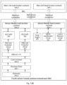
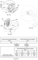
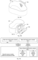
- Fig. 18 illustrates the diagram of the method according to the invention
- the invention is carried out by a modular medical device for monitoring health parameters of a patient, hereafter called in short medical device.
- the medical device of the invention comprises a sharable main unit MU, hereafter called in short main unit MU electrically and mechanically connectable to a sensor module SM.
- the medical device of the invention is configured to acquire one or more bio-signals of the patient corresponding to an anatomic part of the patient, and the medical device is configured to carry out measurements of health parameters by means of configurations of the main unit MU and, respectively of the sensor module SM.
- Said respective configurations of the main unit MU and of the sensor module SM shall be detailed in this section. It shall be understood that the separate disclosure of the respective configurations of the main unit MU and of the sensor module SM is made only for the better understanding of the teaching of the invention. Throughout the invention, it shall be understood that all the configurations of the medical device to carry out the measurements of the health parameters apply when the sensor module SM is electrically and mechanically connected to the main unit MU.
- the sensors used for measuring the health parameters usually include some components that acquire the bio-signals from the patient, for example electric signals or acoustic signals, while other components pre-process and process the acquired bio-signals, the final result being the measurements expressed as meaningful parameters for the health specialist, e.g. heart rate, temperature, or blood oxygenation.
- the health specialist e.g. heart rate, temperature, or blood oxygenation.
- the medical device of the invention is based on two principles.
- the first principle is to have either the sensor module SM or the main unit MU together with the sensor module SM configured for acquiring the bio-signals from the patient and the main unit MU configured for carrying out final processing operations of the bio-signals and outputting the measurements.
- the distributed tasks are depicted symbolically in Fig. 2 as first halves and second halves. All the processing operations except the final processing operations are hereafter called intermediary processing operations. Said intermediary processing operations are distributed among the sensor module SM and the main unit MU.
- the second principle is that the invention discloses various sensor modules SM, which share the same main unit MU for the final processing operations, reason for which the full name of the main unit MU is sharable main unit MU, and, correspondingly, the full name of the medical device of the invention is modular medical device.
- the patient uses a single selected sensor module SM at a time, selected among the various sensor modules SM disclosed in the invention, but he is able to use one sensor modules SM after another.
- sensor module SM shall refer to the selected sensor module SM among the various sensor modules SM.
- the medical device has the advantage of connecting and controlling a wide range of sensors to carry out different specific tasks, overcoming possible incompatibilities between the technical requirements of said sensors, without being too bulky and/or heavy or cumbersome.
- the main unit MU comprises: main unit mechanical means MMM, a main unit array interface MUAI and a processors' sub-unit PSU.
- the main unit mechanical means MMM is configured for detachable mechanical connection of the main unit MU to a sensor module mechanical means SMM of the sensor module SM.
- the shape of the sensor module SM is configured to accommodate partially the main unit MU within a sensor module cavity 201-1 of a sensor module receptacle 201 of the sensor module SM.
- the sensor module mechanical means SMM comprises:
- the main unit array interface MUAI configured for electrical connection of the main unit MU to a sensor module array interface SMAI of the sensor module SM.
- the main unit array interface MUAI comprises:
- the processors' sub-unit PSU comprises:
- the sensor module SM comprises: the sensor module mechanical means SMM, sensors' components SC, the sensor module array interface SMAI, and sensor module enabling components SEC.
- the sensors' components SC are configured to carry out sensor module tasks.
- the sensor module array interface SMAI are arranged within the sensor module cavity 201-1.
- the sensor module array interface SMAI comprise:
- the sensor module enabling components SEC comprise at least:
- main processor and “memory” shall be understood, respectively, as one or more processors, respectively one or more memories.
- the main processor 101 is configured to carry out at least the final processing operations of the main unit MU, and to output the measurements of health parameters.
- the memory 102 is configured to store at least the sensor module tasks of all the sensor modules SM, pre-determined processors' instructions that will be detailed hereafter, the processed measurements as outputted result of the method of the invention, as well as intermediary processing results of the intermediary processing operations.
- the communication drivers 103 are configured to ensure data and command transmission from the main processor 101 to the main unit multi-function electrical contacts 104-2 by means of the one or more programmable multiplexer switches 105 by using communication protocols either directly to said main unit multi-function electrical contacts 104-2 or by means of the enabling components EC, as shown in Fig. 1 and Fig. 7A .
- the communication drivers 103 are configured to ensure data and command transmission from the main processor 101 to the main unit fixed-function electrical contacts 104-1 by means of the enabling components EC and of the one or more simple switches 106 as shown in Fig. 1 .
- Non-limiting examples of communication drivers are: Serial Peripheral Interface SPI, Inter-Integrated Circuit I2C, Universal Serial Bus USB, Inter-IC Sound I2S, Universal Synchronous Receiver UART, General-Purpose Input/Output GPIO, Secure Digital Input Output SOlO.
- the sensor module tasks refer to the configurations for acquiring the bio-signals from the patient and sending the acquired bio-signals to the sensor module array interface SMAI, with or without intermediary processing of said acquired bio-signals by the sensor module SM.
- a typical non-limiting example of sensor module tasks is acquiring electric signals from the heart of the patient necessary to carry out an electrocardiogram.
- the sensor module array interface SMAI is configured for mating the main unit array interface MUAI.
- the sensor module array interface SMAI it is sufficient for the sensor module array interface SMAI to have only the sensor module fixed-function electrical contacts 204-1, complementary to the main unit fixed-function electrical contacts 104-1.
- a non-limiting example is the first sensor module preferred embodiment.
- the sensor module array interface SMAI comprises the sensor module fixed-function electrical contacts 204-1 and sensor module multi-function electrical contacts 204-2, the sensor module multi-function electrical contacts 204-2 being complementary to main unit multi-function electrical contacts 104-2.
- a non-limiting example is the second sensor module preferred embodiment, where both fixed-function and multi-function electrical contacts are used.
- the mechanical connection of the main unit MU to the sensor module SM must ensure, on one hand, that the main unit MU remains firmly engaged to the sensor module SM ensuring their electrical connection while carrying out the measurements, and, on the other hand, the sensor module SM can be easily detached from the main unit MU once the measurements are ended.
- Fig. 3 shows the principles of mechanical connection.
- the shape of the main unit MU and, correspondingly of the sensor module SM, as represented in Fig. 3 is not limiting the scope of the invention.
- the respective shapes and the dimensions of the main unit MU, and, respectively of the sensor module SM depend on the possibility given by the technology to accommodate all the components disclosed in this invention on one hand, and the handy use of the main unit MU and, correspondingly of the sensor module SM by the patient, on the other hand.
- the configurations of the main unit mechanical means MMM and, respectively, of the sensor module mechanical means SMM are such that to ensure the handy attachment and detachment of the main unit MU to the sensor module SM, using the sequence of operations marked with "first" and "second” in Fig. 3A .
- the main unit mechanical means MMM comprises:
- the spring-loaded detents 108-1 can be either mechanical or magnetic.
- the number of spring-loaded detents 108-1 is limited by the possibility to action them by the patient, reason for which, preferably, the number of spring-loaded detents 108-1 is two or three.
- the sensor module receptacle 201 has the sensor module cavity 201-1 configured for partially accommodating the main unit MU within said sensors' unit cavity 201-1.
- the shape of the part of the sensor module receptacle 201 matches the shape of the corresponding part of the main unit MU that is accommodated within said sensors' unit cavity 201-1.
- the dimension of the sensor module cavity 201-1 is such that to ensure the firm engagement of the main unit MU to the sensor module SM.
- the shape and dimension of the two sensor module detent recesses 201-3 are such that to ensure handy connection and disconnection of the sensor module SM from the main unit MU.
- the enabling components EC are electronic components that are not sensors'components, but are configured to enable the use of the main unit sensors' components MUSC together with the sensors' components SC.
- the one or more simple switches 106 are configured for connecting the main unit sensors' components MUSC and the enabling components EC to the main unit fixed-function electrical contacts 104-1, for enabling the mating of the main unit fixed-function electrical contacts 104-1 with the sensor module fixed-function electrical contacts 204-1.
- Fig. 7B is simplified in respect to Fig. 1 to ease the understanding of the connections through the one or more simple switches 106.
- the one or more programmable multiplexer switches 105 are configured for selectively connecting the communication drivers 103 and the enabling components EC to the main unit multi-function electrical contacts 104-2, for enabling the mating of the main unit multi-function electrical contacts 104-2 with the sensor module multi-function contacts 204-2, or with to the sensor module fixed-function electrical contacts 204-1, or with the sensor module multi-function contacts 204-2 and the sensor module fixed-function electrical contacts 204-1.
- Fig. 7A is simplified in respect to Fig. 1 to ease the understanding of the connections through the one or more programmable multiplexer switches 105.
- the main unit fixed-function electrical contacts 104-1 have the same configuration for connecting all the sensor modules SM.
- the main unit multi-function electrical contacts 104-2 have specific configuration for each sensor module SM.
- each programmable multiplexer switch 105 that has one or more inputs from the communication drivers 103 and the enabling components EC and a sole output to one of the main unit multi-function electrical contacts 104-2.
- non-limiting examples of further enabling components EC are as follows:
- the lock-in detection interface 130 is configured together with the sensor module lock-in detection interface 230 to detect when the electrical and mechanical connection of the sensor module SM to the main unit MU is established.
- the identification interface SM ID 131 is configured together with the sensor module identification interface SM ID 231 to recognize the sensor module SM connected to the main unit MU and the associated sensor module tasks of said connected sensor module SM that are loaded in the memory 102.
- main unit sensors' components MUSC are as follows:
- an ECG/BI electrode interface 132 includes one or more ECG/BI electrode interfaces 132, each ECG/BI electrode interface 132 configured for different anatomical part where the various electrodes of the sensor modules SM as described in the invention acquire the electrical signals depending on electrode types like dry or wet electrodes, body and electrode impedance corresponding to said anatomical part.
- the processors' sub-unit PSU is configured to comprise pre-determined processors' instructions stored in the memory 102.
- the pre-determined processors' instructions include but do not limit to the following:
- These instructions enable the processors' sub-unit PSU to recognize that a sensor module SM is electrically and mechanically connected to the main unit MU. These instructions include the powering on of the sensor module SM, where applicable.
- These instructions enable the processors' sub-unit PSU to recognize when the electrical and mechanical connection of the sensor module SM to the main unit MU is established and which are the associated sensor module tasks of said connected sensor module SM that are loaded in the memory 102.
- a lock-in detection pair of corresponding electrical contacts a main unit lock-in detection fixed-function electrical contact 104-1 configured to connect to a sensor module lock-in detection fixed-function electrical contact 204-1.
- the lock-in detection pair of corresponding electrical contacts communicates with the processors' sub-unit PSU by means of the lock-in detection interface 130.
- the lock-in detection interface 130 is configured to disconnect the main unit lock-in detection fixed-function electrical contact 104-1 from the corresponding module lock-in detection fixed-function electrical contact 204-1 .
- the main unit MU further comprises a skin sensors' island area 109.
- the skin sensors' island area 109 comprises one or more main unit optical sensors 109-1, each of the one or more optical sensors 109-1 comprising:
- the shape and the materials of the skin sensors' island area 109 are such that to enable the optical sensors' components to emit, respectively detect light through the one or more light- transfer optical components 109-13.
- the shape and the material of the skin sensors' island sub-areas are such that to enable the one or more main unit contact and/or contactless temperature sensors 109-141 to sense through the skin sensors' area 109.
- the one or more main unit optical sensors 109-1 and the one or more main unit temperature sensors 109-141 belong to the category of the main unit sensors' components MUSC.
- Non-limiting examples of optical sensors 109-1 are: photoplethysmography PPG, photodiodes, charge-connected device CCD sensors, complementary metal-oxide-semiconductor CMOS sensor, etc.
- Each light-detector is spatially separated by each light source by a light separation distance dn.
- Each light-detector together with each light source are configured to generate a light path.
- the light separation distance dn is comprised between a pre-determined minimum light separation distance MIN-dn and a pre-determined maximum light separation distance MAX-dn, the pre-determined minimum light separation distance MIN-dn and the pre-determined maximum light separation distance MAX-dn, depending on a signal quality parameter such as the perfusion index of the anatomic part of the patient.
- Said perfusion index PI is the ratio of the pulsatile blood flow to the non-pulsatile or static blood in peripheral tissue of the anatomic part of the patient.
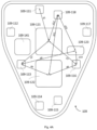
- FIG. 4A and Fig. 4B A non-limiting example of realization is shown in Fig. 4A and Fig. 4B , where the light sources are represented by eight light emitting diodes LEDs with reference numbers from 109-111 to 109-118 and the light detectors are represented by 3 photodiodes with reference numbers from 109-121 to 109-123.
- the number of light paths 109-15 is 24 resulting from the combination of the 8 light emitting diodes LEDs from 109-111 to 109-118 and 3 photodiodes from 109-121 to 109-123.
- the light separation distances dn are represented in Fig. 4A , in particular the light separation distance d1 between the light emitting diode LED 109-111 and the photodiode 109-121, the light separation distance d12 between the light emitting diode LED 109-118 and the photodiode 109-121, etc.
- Fig. 4A and Fig. 4B illustrates the dynamically configurable optical sensor light path for a range of anatomically body places with different perfusion indexes.
- the skin sensors' island area 109 further includes: contact microphones, radar sensor, ultrasound piezo sensor, laser interferometer sensor for micro skin/blood vessels displacement detection, not represented graphically.
- the light separation distance dn When the light separation distance dn enables best signal quality for the respective anatomic part and the specific measurement, the light separation distance dn becomes an optimal light separation distance dn.
- the best signal quality for reflective PPG sensor for various anatomic parts of the patient requires different geometrical separation distances between the light sources and the light-detectors.
- the light separation distances dn varies between 2. 58- 5.53 mm; if the anatomical part is the arm, the light separation distances dn varies between 6.25-7.46mm; whereas if the anatomical part is the chest, the light separation distances dn varies between 7.49-12.82mm, as it is shown in Fig. 4B .
- the one or more light - transfer optical components for the one or more optical sensors 109-1 comprises an optically transparent or a translucent material arranged to face the skin of the patient. Facing of the skin of the patient may be carried out either in physical contact with the patient or without physical contact, ensuring only optical contact.
- the medical device is configured to be used by two or more patients by further comprising means for identifying the patient including at least:
- the biometric sensors 112 belong to the category of the main unit sensors' components MUSC.
- the processors' sub-unit PSU further comprises the wireless connection module 121, configured to connect the main unit MU to the one or more external devices in order to be use the measurements for monitoring the health parameters of the patient.
- Said external devices can be handheld devices such as phone, tablets, or processing units such as computers, laptops, or storage devices including the cloud or cloud-like storage means.
- wireless connection module 121 it is advantageous to have the wireless connection module 121 as unique, centralized connection to the one or more external devices regardless of the selected sensor modules SM.
- the processors' sub-unit PSU further comprises the artificial intelligence processor 124, configured for:
- the invention discloses an example of realization of the main unit MU for an easier understanding of the invention.
- main unit MU of the invention is such that the main unit can be easily held in the hand of the patient or worn on the body.
- the main unit MU of the invention is configured to be connected to the sensor module SM on one side of the main unit MU.
- the shape of the MU of the example of realization is symmetrical and oval-shaped, having a narrower portion and a wider portion. This shape is one of the numerous shapes possible without departing from the scope of the invention. Other possible shapes are: round, squared, irregular shape.
- the main unit MU of the example of realization illustrates a combination of all the previously-disclosed preferred embodiments as it includes the skin sensors' island area 109, the means for identifying the patient and the artificial intelligence processor.
- the following components of the main unit MU are disclosed hereafter starting from the side opposite to the side of connection the main unit MU to the sensor module SM.
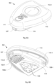
- the main unit MU has a top cover 113, a bottom cover 114, one or more batteries 110, and one printed circuit board PCB 115 on which the respective subcomponents of the processors' sub-unit PSU and of the main unit sensors' components MUSC as well as the one or more biometric sensors 112 are placed according to known techniques.
- the person skilled in the art knows that it is possible to use two or more printed circuit boards PCB 115 to accommodate the afore-mentioned electronic components without departing from the teaching of the invention, as Fig. 5 shows for simplicity a single printed circuit board PCB 115.
- the printed circuit board PCB 115 further accommodates the artificial intelligence processor 124, not represented graphically in Fig. 5 but represented in Fig. 7C .
- Fig. 5 also discloses a buzzer 116, placed on the printed circuit board PCB 115 configured to provide acoustic feedback such as when the measurements detect anomalous values, or when there is an error which prevents the medical device to function properly.
- the printed circuit board PCB 115 may further accommodate a haptic interface controller 117, a wireless connection module 121 such as Bluetooth, RFID, GSM, GPS module, an electromagnetic shield.
- a wireless connection module 121 such as Bluetooth, RFID, GSM, GPS module, an electromagnetic shield.
- the one or more biometric sensors 112 and the buzzer 116 are fixed on the top cover 113.
- the main unit fixed-function electrical contacts 104-1 and the main unit multi-function electrical contacts 104-2 are either accommodated on a separate PCB, not represented graphically, or directly inserted in the material of the bottom cover 114, for example by using the over molding injection technique.
- the one or more batteries 110 are configured to power the main unit MU, according to prior art.
- the top cover 113 has a button hole 113-1 and an on-off button 113-2 accommodated in the button hole 113-1.
- the on-off button 113-2 When the on-off button 113-2 is pressed by the patient, once the main unit MU is mechanically connected to the sensor module SM, the electrical connection is established, and the medical device of the invention can be used.
- the presence of the on-off button 113-2 is optional in the main unit MU, as the main unit MU can be powered on when mechanically and electrically connected to the sensor module SM and, when not in use, can be configured to entry into a stand-by mode.
- the fingerprint biometric area 111 is placed on the top cover 113, as seen in Fig.5 and Fig. 6 .
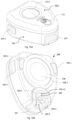
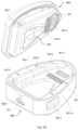
- the bottom cover 114 accommodates the main unit mechanical means MMM, as seen from Fig. 6 , Fig. 7A and Fig. 7B .
- the guiding element 107 is placed centrally in the narrower portion of the main unit, the spring-loaded detent mechanism is mechanical and the number of spring-loaded detents 108-1 is two, placed symmetrically in respect to the guiding element 107.
- the bottom cover 114 has an outer gasket 114-1 and an inner gasket 114-2.
- the outer gasket 114-1 is configured to seal the bottom cover 114 so that the medical device be water-resistant or waterproof once the main unit MU mechanically connected to the sensor module SM.
- Fig. 6B show schematically the main unit fixed-function electrical contacts 104-1 and the main unit multi-function electrical contacts 104-2, the graphical representation of which is symbolical and not limitative.
- the portion surrounding the fixed-function electrical contacts 104-1 is sealed by the inner gasket 114-2. It is possible that the inner gasket 114-2 seals the main unit multi-function electrical contacts 104-2 or the main unit fixed-function electrical contacts 104-1 and the main unit multi-function electrical contacts 104-2.
- the inner gasket 114-2 has double role: on one side reinforcing the sealing against water, including patient's sweat, for the respective electrical contacts and, on the other side, compensating for a possible height difference of the portion surrounding the respective electrical contacts and the general surface of the bottom cover 114 facing the sensor module SM.
- the skin sensors' island area 109 is shown schematically, including the optically transparent or a translucent material arranged to face the skin of the patient.
- the main processor 101 communicates with the power management unit 120, the power management unit 120 being in contact with the battery 110 and with the power output interface 128, the power output interface 128 being configured to power the sensor module SM.
- the main processor 101 communicates with the memory 102, with the communication drivers 103, with the main unit sensors' components MUSC and with the enabling components EC for transmitting the instructions through the one or more programmable multiplexer switches 105 and through the one or more simple switches 106.
- non-limiting examples of the main unit sensors' components MUSC with whom the main processor 101 communicates are as follows:
- connection of the contact microphone array 122 and of the voice microphone 123 with the main processor 101 is done through the artificial intelligence processor 124 for the embodiments that include said artificial intelligence processor 124.
- the reason of connecting the contact microphone array 122 and of the voice microphone 123 with the main processor 101 through the artificial intelligence processor 124 is that said artificial intelligence processor 124 is already configured to be optimized to process "always on" audio signals and to output detected classified commands to the main processor only if predetermined sound conditions are fulfilled, for example if the specific sounds captured from the heart and lungs in case of the contact microphone array 122 are of interest, such as cough or anomalies in the mechanical activity of the heart such as heart murmur.
- connection of the contact microphone array 122 and of the voice microphone 123 with the main processor 101 is done directly.
- the main processor 101 communicates with the main unit sensors' components MUSC that enhance the functioning of the invention:
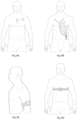
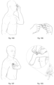
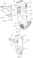
- Figures 8A, 8B, 8C and 8D illustrate non-limiting examples of positioning the medical device corresponding, respectively, to the first preferred embodiment of the sensor module - Fig. 8A , the fourth first preferred embodiment of the sensor module - Fig. 8B , the seventh first preferred embodiment of the sensor module - Fig. 8C and the fifth first preferred embodiment of the sensor module - Fig. 8D .
- the first sensor module preferred embodiment is used for continuous measurements of health parameters related to the activity of the heart and/or lungs over a preset period as prescribed by the health specialist- for example two weeks.
- the memory 102 is configured to store the measurements for said preset period and the sensor module SM of the first sensor module preferred embodiment is configured to be worn on the skin of the patient during said preset period, as shown in Fig. 8A .
- the position of the sensor module of the first sensor module preferred embodiment on the chest of the patient is not limited by the two examples depicted in Fig. 8A .
- the sensor module SM further comprises sensor module attaching means, and sensors' components SC.
- the sensor module attaching means are configured to accommodate the sensor module array interface SMAI and configured to attach the sensor module SM to the chest of the patient, when the first sensor module preferred embodiment is selected to be mechanically and electrically connected to the main unit MU.
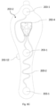
- the sensor module attaching means comprise a flexible foil 202.
- the flexible foil 202 has a flexible foil first side 202-1 and a flexible foil second side 202-2.
- the sensor module receptacle 201 is fixed on the flexible foil first side 202-1 and the flexible foil second side 202-2 is configured for skin attachment on the chest of the patient, similarly to the attachment of a medical patch.
- the sensor module array interface SMAI of the first sensor module preferred embodiment comprises only sensor module fixed-function electrical contacts 204-1.
- the sensors' components EC of the sensor module SM comprise a printed electronic assembly electrode 203, arranged on the flexible foil second side 202-2.
- the printed electronic assembly electrode 203 is configured to acquire electrical signals from the chest of the patient.
- the electrical signals refer to the functioning of the heart and to the respiration parameters, said respiration parameters reflected by the bio-impedance of the skin.
- the printed electronic assembly electrode 203 is configured to connect to the sensor module fixed-function electrical contacts 204-1 arranged on the flexible foil first side 202-1.
- the printed electronic assembly electrode 203 comprises:
- the main unit fixed-function electrical contacts 104-1 are configured to be connected to the sensor module fixed-function electrical contacts 204-1 and the sensor module fixed-function electrical contacts 204-1 are connected at least to the printed electronic assembly electrode 203, to the sensor module lock-in detection interface 230, and to the sensor module identification interface SM ID 231.
- the main unit sensors' components MUSC further comprise at least the following:
- the one or more main unit optical sensors 109-1 as well as one or more main unit temperature sensors 109-141 are configured to sense through the one or more light- transfer optical components 109-13.
- the sensor module receptacle 201 has a sensor module receptacle opening 201-11 matching the shape of the skin sensors' island area 109 in order to accommodate said skin sensors' island area 109.
- the flexible foil 202 contains a flexible foil opening 202-4 matching the shape of the skin sensors' island area 109, the flexible foil opening 202-4 configured to allow said skin sensors' island area 109 be in physical contact with the patient's skin.
- said contact microphone array 122 is configured to auscultate the sounds of the heart or the lungs through said skin sensors' island area 109.
- the configurations of the flexible foil 202 must respond to numerous challenges among which the following:
- FIG. 9D An example of realization with reference to Fig. 9D discloses the components of the flexible foil 202, starting with the second side of the flexible foil 202-2 which is fixed on patient's chest:
- the number of printed electrical pads holes 202-231 matches the number of printed electrical pads 203-1.
- the number of the printed electrical pads 203-1 as shown in Fig. 9D is not limiting the invention.
- the flexible electric contact support 202-241 must be at the same time sufficiently flexible to ensure its folding and sufficiently stiff to avoid crumbling during assembly. Flexibility is ensured by using a flexible material, such as low-density polyethylene, polyethylene terephthalate, polyurethane, polyester, silicone, fabric, nonwoven fabric, paper, or a combination of two or more from the afore-mentioned materials, whereas stiffness is ensured by using the flexible non-stretchable foil reinforcement membrane 202-25.
- a flexible material such as low-density polyethylene, polyethylene terephthalate, polyurethane, polyester, silicone, fabric, nonwoven fabric, paper, or a combination of two or more from the afore-mentioned materials
- the materials of the flexible foil 202 permit re-use of the flexible foil 202, after having finished the measurements and after having disconnected the sensor module SM from the main unit MU, said flexible foil 202 can be used again.
- Fig. 9E Fig. 9E
- Fig. 9F Fig. 9G
- the details of the flexible foil 202 of the three alternative examples of Fig. 9E , Fig. 9F and Fig. 9G are illustrated in Fig. 9D and are disclosed above, making reference to the preferred embodiments that comprise the skin sensors' island area 109.
- All three alternative examples refer to the sensor module attaching means.
- the configurations of the electrical coupling of the sensor module array interface SMAI and the configurations of the printed electronic assembly electrode 203 for acquiring the bio-signals are the same for all three alternative examples, whereas the attaching means and the positioning of the various components of the printed electronic assembly electrode 203 are different.
- the sensor module fixed-function electrical contacts 204-1 are arranged on the flexible support 202-241 of the flexible foil second side 202-2, and the sensor module receptacle 201 has the sensor module receptacle opening 201-11.
- the flexible electric contact support 202-241 and the sensor module receptacle opening 201-11 are configured to enable the fetching of the sensor module fixed-function electrical contacts 204-1 from the electrode foil second side 202-2 to the electrode foil first side 202-1 by folding said flexible electric contact support 202-241 through said sensor module receptacle opening 201-11 such that said sensor module fixed-function electrical contacts 204-1 be in electrical contact with the main unit fixed-function electrical contacts 104-1.
- Fig. 9E schematically shows how the flexible electric contact support 202-241 is configured to be foldable.
- the flexible electric contact support 202-241 is firstly passed through the sensor module receptacle opening 201-11, then folded on the sensor module receptacle electric contacts recess area 201-12 until the flexible electric contact support 202-241 covers the entire sensor module receptacle electric contacts recess area 201-12.
- the sensor module fixed-function electrical contacts 204-1 are arranged on the flexible electric contact support 202-241.
- the flexible electric contact support 202-241 is arranged to be folded such that to enable fetching of said sensor module fixed-function electrical contacts 204-1 from the flexible foil second side 202-2 to the flexible foil first side 202-1.
- the sensor module receptacle 201 has a sensor module receptacle aperture 201-13.
- the sensor module receptacle aperture 201-13 is positioned within the sensor module cavity 201-1 matching the size and position of the sensor module fixed-function electrical contacts 204-1 arranged on the flexible electric contact support 202-241.
- the flexible electric contact support 202-241 and the sensor module receptacle aperture 201-13 are configured to enable said sensor module fixed-function electrical contacts 204-1 to be in electrical contact with the main unit fixed-function electrical contacts 104-1.
- the flexible foil 202 is configured to accommodate an electric circuit stiffener 202-3 for the sensor module fixed-function electrical contacts 204-1, the electric circuit stiffener 202-3 being mechanically and electrically secured on the flexible foil 202.
- the sensor module receptacle 201 has a sensor module receptacle electric contacts aperture 201-13, the sensor module receptacle electric contacts aperture 201-13 accommodating the sensor module fixed-function electrical contacts 204-1 arranged on the electric circuit stiffener 202-3.
- the sensor module receptacle electric contacts aperture 201-13 is positioned within the sensor module cavity 201-1, the sensor module receptacle electric contacts aperture 201-13, matching the size and the position of the sensor module fixed-function electrical contacts 204-1.
- the sensor module receptacle recess area 201-12 is dimensioned and positioned within the receptacle 201 to accommodate the electric circuit stiffener 202-3 and ensure the correct position of the sensor module fixed-function electrical contacts 204-1.
- the electric circuit stiffener 202-3 is preferably a printed circuit board PCB or a polyethylene terephthalate PET, the electric circuit stiffener 202-3 being provided with two-sides contact vias 202-311.
- the electric circuit stiffener 202-3 has two sides: a first electric circuit stiffener side 202-31, the first electric circuit stiffener side 202-31 oriented towards the main unit MU, and a second electric circuit stiffener side 202-32, the second electric circuit stiffener side 202-32 oriented opposite the main unit MU.
- the electric circuit stiffener 202-3 is provided with two-sides contact vias 202-311, each of the two-sides contact vias 202-311 having a contact vias' first side and a contact vias' second side, the contact vias' first side and the contact vias' second side not represented graphically.
- the contact vias' first side is on the same side with the first electric circuit stiffener side 202-31, whereas the contact vias' second side is on the second side with the second electric circuit stiffener side 202-32.
- the first electric circuit stiffener side 202-31 is configured to accommodate the sensor module fixed-function electrical contacts 204-1 and the contact vias' first side.
- Said contact vias' first side is configured to be in electrical contact with the sensor module fixed-function electrical contacts 204-1.
- the second electric circuit stiffener side 202-32 is configured to be secured on the flexible foil first side 202-1 and to accommodate the contact vias' second side, the contact vias' second side being in electrical contact with printed electrical vias 202-5 by means of an electrically-conductive adhesive,
- the printed electrical vias 202-5 are configured to be electrically connected with the printed electrical trace 203-2.
- the first alternative example is suitable for manufacturing using semi-automatic production lines with low-end robots' assembly machine; it may require more manual process steps and human labor, whereas the second and the third alternative examples are suitable for manufacturing using automatic assembly robotic lines, being cost effective for very high production volumes.
- the second sensor module preferred embodiment is used for spot measurements of health parameters related to the activity of the cardiovascular system, that includes the heart's electrical activity, mechanical heart activity, the blood parameters like oxygen saturation, blood pressure, respiratory system, as well as the temperature.
- the sensor module SM of the second sensor module preferred embodiment acquires on demand spot measurements of the bio-signals from the patient while the medical device carries out spot measurements and stores the measurements in the memory 102.
- spot is determined by the customary duration for each measurement according to medical practice, i.e. 30 seconds.
- the one or more bio-signals are acquired from the patient from different parts of the body of the patient, such as: the chest, the left knee join, the thumb fingers of the hands, ankle join.
- the sensor module SM further comprises the following sensors' components SC:
- the main unit sensors' components MUSC further comprise at least the following:
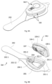
- the non-limiting example of shape of the sensor module SM as shown in with reference to Figures 10A - 10G is optimized to be hand-held and to acquire the bio-signal from irregular surfaces of different parts of the body of the patient mentioned above.
- the shape the sensor module SM is an isosceles triangle in cross-section, with rounded angles.
- the pair of finger lateral electrodes 205-1, 205-2 is placed on the lateral equal sides, whereas the multi-function electrode 207 is placed in any vertex of the triangle opposite to the pair of finger lateral electrodes 205-1, 205-2, in order to ensure a good contact with the fingers that have a round shape, the chest that is plane and with the knee join which is concave.
- the multi-function electrode 207 it is designed as a L-shape, having a first side of the L placed on the external surface of the sensor module receptacle 201 in the same axis plane with the pair of finger lateral electrodes 205-1, 205-2, said first side of the L designed as a convex surface to enable its accommodation on surface of the join knee.
- the second side of the L is provided in the center with a finger recess 209-3, configured to accommodate any finger of the patient.
- the second side of the L has flat margins, the flat margins placed around the finger recess 209-3 in the same plane with the pair of bottom electrodes 206-1, 206-2 and with the stethoscope diaphragm 208-1.
- the finger recess 209-3 is configured to accommodate the skin sensor module optical area 209.
- the sensor module of the second sensor module preferred embodiment is further provided with an USB port 211, the USB port 211 configured for connecting the sensor module to a power supply for charging or to another external device, e.g. a personal computer PC, laptop for data downloading or configuration.
- a personal computer PC personal computer PC
- laptop for data downloading or configuration.
- the sensor module SM further comprises a sensor module multiplexer switch 210, the sensor module multiplexer switch 210 configured to selectively connect the pair of finger lateral electrodes 205-1, 205-2, the pair of bottom electrodes 206-1, 206-2 and the multi-function electrode 207, to the second electrocardiogram analogue front end ECG AFE component 226 and to the sensor module multi-function contacts 204-2 and to the sensor module fixed-function electrical contacts 204-1 creating one closed loop with the patient body from the list below:
- the sensor module SM of the second sensor module preferred embodiment comprises both the sensor module fixed-function electrical contacts 204-1 and the module multi-function electrical contacts 204-2, as depicted in Fig. 10H .
- the second sensor module preferred embodiment has eight alternative examples of use.
- the one or more programmable multiplexer switches 105 are configured for selectively connecting the communication drivers 103 and the enabling components EC to the sensor module multi-function contacts 204-2, the sensor module multi-function contacts 204-2 corresponding to one of the closed loops, and/or to the sensors' components SC, according to the selection of one option from the list below:
- the measurements refer to pulse rate and pulse oximetry, such as arterial oxygen saturation SpO2.
- the contact of the sensor module SM with the patient is done by placing the sensor module such that the one or more sensor module optical sensors 209-1 to be in contact with skin of the patient.
- a non-limiting example of placing of the one or more sensor module optical sensors 209-1 in contact with the skin of the patient is positioning any finger of the patient on the finger recess 209-3.
- the one or more programmable multiplexer switches 105 selectively connect the communication drivers 103 and the enabling components EC to the sensor module multi-function contacts 204-2 corresponding to the one or more sensor module optical sensors 209-1.
- a non-limiting example of type of sensor module optical sensors 209-1 is the photoplethysmography sensor PPG 209-1.
- the measurements are carried out by the photoplethysmography sensor PPG 209-1, while the final processing operations are carried out by the main unit MU.
- the pair of finger lateral electrodes 205-1, 205-2, the pair of bottom electrodes 206-1, 206-2, the multi-function sensor module electrode 207 the stethoscope 208, and the one or more forehead temperature sensors 209-2 are deactivated.
- said skin sensors' island area 109 is deactivated.
- the measurements refer to the temperature.
- the contact of the sensor module SM with the patient is done by placing the sensor module SM such that the one or more forehead temperature sensors 209-2 to be in contact with skin of the patient as depicted Fig. 10D .
- the measurements are carried out by the one or more forehead temperature sensors 209-2, while the final processing operations are carried out by the main unit MU.
- the pair of finger lateral electrodes 205-1, 205-2, the pair of bottom electrodes 206-1, 206-2, the multi-function sensor module electrode 207, the stethoscope 208, and the one or more sensor module optical sensors 209-1 are deactivated.
- said skin sensors' island area 109 is deactivated.
- the measurements refer to the sounds of the heart and/or lungs by using the stethoscope 208.
- the contact of the sensor module SM with the patient is done by placing the sensor module such that to ensure the contact of the stethoscope diaphragm 208-1 on well-defined areas on the chest or the back of the patient as it is presented in Fig. 10F .
- the sensor module further comprises the following module enabling components SEC:
- the one or more programmable multiplexer switches 105 selectively connect the communication drivers 103 and the enabling components EC to the sensor module multi-function contacts 204-2 corresponding to the stethoscope 208.
- the programmable multiplexer switch 105 uses three main unit multi-function electrical contacts 104-2 and the Inter-IC Sound I2S drivers 103 to connect to a stethoscope Inter-IC Sound I2S interface, the stethoscope Inter-IC Sound I2S interface not represented graphically. Said Inter-IC Sound I2S drivers 103 are configured for audio streaming.
- the programmable multiplexer switch 105 uses two main unit multi-function electrical contacts 104-2 and the Inter-Integrated Circuit I2C drivers 103 to connect to a stethoscope Inter-Integrated Circuit I2C interface, the stethoscope Inter-Integrated Circuit I2C interface not represented graphically.
- Said Inter-Integrated Circuit I2C drivers 103 are configured to command a stethoscope encoder, the stethoscope encoder not represented graphically.
- the programmable multiplexer switch 105 uses six main unit multi-function electrical contacts 104-2 and the Secure Digital Input Output SOlO drivers 103 to connect to the high throughput wireless communication protocol module 221 for carrying out audio streaming.
- the sensor module lock-in detection interface 230 connect to the lock-in detection interface 130, whereas the sensor module identification interface SM ID 231 connect to the identification interface SM ID 131.
- the power supply 228 mates the power output interface 128 for powering the sensor module SM.
- the measurements are carried out by the stethoscope 208 while the final processing operations are carried out by the main unit MU, or by the stethoscope 208 jointly with the voice microphone 123 used for noise reduction by noise cancelation techniques.
- the pair of finger lateral electrodes 205-1, 205-2, the pair of bottom electrodes 206-1, 206-2, the multi-function sensor module electrode 207, the one or more sensor module optical sensors 209-1 and the one or more forehead temperature sensors 209-2 are deactivated.
- said skin sensors' island area 109 is deactivated.
- the measurements refer to the electrocardiogram by activating the first closed loop.
- the contact of the sensor module SM with the patient is done by placing the thumb and index fingers from one hand of the patient on the pair of finger lateral electrodes 205-1, 205-2 while the index or thumb finger from the other hand or any other part of the body e.g. wrist on the multi-function electrode 207, acquiring in this way said one or more bio-signals, as depicted Fig.10E .
- the sensor module multiplexer switch 210 selectively connects the pair of finger lateral electrodes 205-1, the multi-function electrode 207 to the sensor module fixed-function electrical contacts 204-1 creating the first closed loop.
- the one or more programmable multiplexer switches 105 selectively connect the communication drivers 103 and the enabling components EC to the sensor module multi-function contacts 204-2 corresponding to the first loop.
- the measurements are carried out by the first loop jointly with the first electrocardiogram analogue front end ECG AFE component 126, the ECG/BI electrode interface 132 and the motion sensor component 125 for noise reduction.
- the bio-impedance component 127 can also be used in this fourth alternative example in combination with the afore-mentioned sensor components for evaluating the level of stress of the patient.
- the final processing operations are carried out by the main unit MU.
- the pair of bottom electrodes 206-1, 206-2, as well as the stethoscope 208, one or more sensor module optical sensors 209-1, the second electrocardiogram analogue front end ECG AFE component 226, and the one or more forehead temperature sensors 209-2 are deactivated.
- said skin sensors' island area 109 is deactivated.
- the measurements refer to electrocardiogram, carried out differently from the fourth alternative example, by activating the second closed loop.
- the contact of the sensor module SM with the patient is done by placing the sensor module on the chest or the back of the patient, ensuring the contact of the pair of bottom electrodes 206-1, 206-2 and of the second side of the multi-function electrode 207 with the skin, as depicted in Fig. 10F .
- the measurements are carried out by the second closed loop jointly with the second electrocardiogram analogue front end ECG AFE component 226, while the final processing operations are carried out by the main unit MU, or by the second closed loop jointly with the second electrocardiogram analogue front end ECG AFE component 226 and with the motion sensor component 125 for noise reduction.
- the pair of finger lateral electrodes 205-1, 205-2, as well as the stethoscope 208, the one or more sensor module optical sensors 209-1, and the one or more forehead temperature sensors 209-2 are deactivated.
- said skin sensors' island area 109 is deactivated.
- the measurements refer to the electrocardiogram carried out accordingly to Einthoven's triangle method, activating the third closed loop.
- the contact of the sensor module SM with the patient is done by placing one thumb finger of one hand on the first bottom electrode 206-1, the other thumb finger of the other hand on the second bottom electrode 206-2 and by placing the first side of the L-shape of the multi-function electrode 207 on the left leg knee join or, alternatively on the left leg ankle, realizing the Einthoven triangle design, as depicted in Fig. 10G .
- the measurements are carried out by the third closed loop jointly with the second electrocardiogram analogue front end ECG AFE component 226, while the final processing operations are carried out by the main unit MU, or by the third closed loop jointly with the second electrocardiogram analogue front end ECG AFE component 226 and with the motion sensor component 125 for noise reduction.
- the pair of finger lateral electrodes 205-1, 205-2, as well as the stethoscope 208, the one or more sensor module optical sensors 209-1, and the one or more forehead temperature sensors 209-2 are deactivated.
- said skin sensors' island area 109 is deactivated.
- the measurements refer to the electrocardiogram activating the first closed loop jointly with the one or more sensor module optical sensors 209-1, as well as pulse rate, the arterial oxygen saturation SpO2, heart rate.
- the contact of the sensor module SM with the patient is done by placing the thumb and index fingers from one hand of the patient on the pair of finger lateral electrodes 205-1, 205-2, and simultaneously placing the finger of the other hand on the finger recess 209-3 such that the one or more sensor module optical sensors 209-1 to be in contact with the finger of the other hand, this finger of the other hand being simultaneously in contact with the multi-function electrode 207, as depicted Fig.10E .
- the sensor module multiplexer switch 210 selectively connects the pair of finger lateral electrodes 205-1, the multi-function electrode 207 to the second electrocardiogram analogue front end ECG AFE component 226 creating the first closed loop.
- the one or more programmable multiplexer switches 105 selectively connect the communication drivers 103 and the enabling components EC to the sensor module multi-function contacts 204-2 corresponding to the first loop and to the one or more sensor module optical sensors 209-1, the one or more sensor module optical sensors 209-1 jointly with the second electrocardiogram analogue front end ECG AFE component 226.
- the final processing operations carried out by the main unit MU include synchronization and/or fusing of the above two intermediary measurements.
- the pair of bottom electrodes 206-1, 206-2, as well as the stethoscope 208, and the one or more forehead temperature sensors 209-2 are deactivated.
- said skin sensors' island area 109 is deactivated.
- the measurements refer to the heart and/or lungs auscultation combined with the electrocardiogram, usually named phonocardiogram PCG, by activating the second closed loop and the stethoscope 208.
- the contact of the sensor module SM with the patient is done by placing the sensor module on the chest or the back of the patient, ensuring the contact of the pair of bottom electrodes 206-1, 206-2 and of the second side of the L-shape of the multi-function electrode 207 with the skin, as depicted in Fig. 10F , and, at the same time by placing the stethoscope 208 on the chest and/or back of the patient by means of the stethoscope diaphragm 208-1, as depicted in Fig. 10F .
- the measurements are carried out by the second closed loop jointly with the stethoscope 208 and with the second electrocardiogram analogue front end ECG AFE component 226, or by the second closed loop jointly with the stethoscope 208 and with the second electrocardiogram analogue front end ECG AFE component 226 and with the motion sensor component 125 for noise reduction.
- the final processing operations are carried out by the main unit MU.
- the pair of finger lateral electrodes 205-1, 205-2, as well as one or more sensor module optical sensors 209-1 and the one or more forehead temperature sensors 209-2 are deactivated.
- said skin sensors' island area 109 is deactivated.
- a right-leg-driver RLD function is assigned to one of the pair of bottom electrodes 206-1, 206-2 or to one of the pair of finger lateral electrodes 205-1, 205-2.
- the noise level of the acquired ECG electrical signal is reduced.
- the third sensor module preferred embodiment is used for clinical video examination and spot measurements of health parameters related to the general patient health, activity of the cardiovascular system or hemodynamic parameters, that includes the heart's electrical activity, mechanical heart activity, the blood parameters like oxygen saturation, blood pressure, lung auscultation examination and respiratory rate, the temperature, video inspection of the throat and/or ears, video inspection of the skin for dermatological purposes, auscultation of the abdomen.
- the sensor module SM of the third sensor module preferred embodiment acquires on demand spot measurements of the bio-signals from the patient while the medical device carries out spot measurements, stores the measurements in the memory 102, or send them through a/the wireless connection module 121 to external devices.
- spot is determined by the customary duration for each measurement according to medical practice, i.e. 30 seconds.
- the one or more bio-signals are acquired from the patient from different parts of the body of the patient, such as: the chest, the left knee join, the thumb fingers of the hands, ankle join, the throat and/or ears, and the abdomen.
- the sensor module SM further comprises the following sensors' components SC:
- the video camera 236-1 and the infrared thermal imaging camera 236-2 are placed in a video camera area 236, the video camera area 236 placed on the same side of the sensor module receptacle 201 with the skin sensor module optical area 209.
- the video camera area 236 accommodates two or more LEDs 236-5 for illuminating the area to be examined.
- the sensor module SM further comprises an images signal processor ISP 239, the images signal processor ISP 239 configured to carry out intermediary processing and compression of the images and video stream acquired from the video camera 236-1 and from the infrared thermal imaging camera 236-2.
- the main unit sensors' components MUSC further comprises:
- the non-limiting example of shape of the sensor module SM as shown in with reference to Fig. 11A and Fig. 11B , is optimized to be hand-held and to acquire the bio-signal from irregular surfaces of different parts of the body of the patient mentioned above.
- the shape of the sensor module receptacle 201 is elongated having the longitudinal axis significantly larger than the cross-section axis.
- the stethoscope 208 is placed at one end of the longitudinal axis, whereas the multi-function electrode 207 is placed at the other end, creating a vertex of the sensor module receptacle 201 in order to ensure a good contact with the fingers that have a round shape, the chest that is plane, the knee join and the ankle.
- the pair of finger lateral electrodes 205-1, 205-2 is placed on the lateral equal sides in the proximity of the stethoscope 208.
- the multi-function electrode 207 it is designed as a L-shape, having a first side of the L placed in the same axis plane with the pair of finger lateral electrodes 205-1, 205-2, said first side of the L designed as a convex surface to enable its accommodation on surface of the join knee.
- the second side of the L is provided with a finger recess 209-3, configured to accommodate any finger of the patient.
- the second side of the L has flat margins, the flat margins placed around the finger recess 209-3.
- the finger recess 209-3 is configured to accommodate the skin sensor module optical area 209.
- the sensor module of the third sensor module preferred embodiment is further provided with an USB port 211, the USB port 211 configured for connecting the sensor module to a power supply for charging or to another external device e.g. PC, laptop for data downloading or configuration.
- a power supply for charging or to another external device e.g. PC, laptop for data downloading or configuration.
- another external device e.g. PC, laptop for data downloading or configuration.
- the sensor module SM further comprises a sensor module multiplexer switch 210, the sensor module multiplexer switch 210 configured to selectively connect the pair of finger lateral electrodes 205-1, 205-2, and the multi-function electrode 207 and the second electrocardiogram analogue front end ECG AFE component 226 to the sensor module multi-function contacts 204-2 and to the sensor module fixed-function electrical contacts 204-1 creating one closed loop with the patient body from the list below:
- the sensor module further comprises the following enabling components SEC:
- the sensor module SM of the third sensor module preferred embodiment comprises both the sensor module fixed-function electrical contacts 204-1 and the module multi-function electrical contacts 204-2, as depicted in Fig. 11C .
- the third sensor module preferred embodiment has eight alternative examples of use.
- the one or more programmable multiplexer switches 105 are configured for selectively connecting the communication drivers 103 and the enabling components EC to the sensor module multi-function contacts 204-2, the sensor module multi-function contacts 204-2 corresponding to one of the closed loops, and/or to the sensors' components SC, according to the selection of one option from the list:
- the first four alternative examples of use of the third sensor module preferred embodiment are identical with the respective first four alternative examples of use of the second sensor module preferred embodiment.
- the sixth alternative example of use of the third sensor module preferred embodiment is identical with the seventh alternative example of use of the second sensor module preferred embodiment.
- the measurements refer to the electrocardiogram carried out accordingly to Einthoven's triangle method, activating the second closed loop.
- the contact of the sensor module SM with the patient is done by placing one thumb finger of one hand on the first finger lateral electrode 205-1, the other thumb finger of the other hand on the second finger lateral electrode 205-2 and by placing the multi-function electrode 207 on the left leg knee join or, alternatively on the left leg ankle, realizing the Einthoven triangle design, not represented graphically.
- the one or more programmable multiplexer switches 105 selectively connect the communication drivers 103 and the enabling components EC to the sensor module multi-function contacts 204-2 corresponding to the second closed loop.
- the measurements are carried out by the second closed loop jointly with the second electrocardiogram analogue front end ECG AFE component 226, while the final processing operations are carried out by the main unit MU, or by the second closed loop jointly with the second electrocardiogram analogue front end ECG AFE component 226 and with the motion sensor component 125 for noise reduction.
- the stethoscope 208, one or more sensor module optical sensors 209-1 and the one or more forehead temperature sensors 209-2 are deactivated.
- said skin sensors' island area 109 is deactivated.
- the video camera 236-1 is configured to acquire images from the throat and ears of the patient or from the skin.
- the one or more programmable multiplexer switches 105 selectively connect the communication drivers 103 and the enabling components EC to the sensor module multi-function contacts 204-2 corresponding to the video camera 236-1.
- the tongue depressor assembly 236-11 has an L-shape, having on one side a tongue fixing frame 236-111 and, on the other side, a tongue depressor 236-112.
- the tongue fixing frame 236-111 is attached to the video camera area 236 by means of a video camera area spring-loaded detent mechanism 236-4, said video camera area spring-loaded detent mechanism 236-4 matching video camera area guiding recesses 236-3, the video camera area guiding recesses 236-3 placed on the edges of the video camera area 236.
- the tongue depressor 236-112 is used to hold still the tongue of the patient while the video camera 236-1 acquires images.
- the otoscope adaptor 236-12 comprises an otoscope fixing frame 236-121 and an otoscope 236-122, the otoscope 236-122 prolonging the otoscope fixing frame 236-121.
- otoscope fixing frame 236-121 is attached to the video camera area 236 by means of the video camera area spring-loaded detent mechanism 236-4.
- the images acquired by the video camera 236-1 undergo intermediary processing and compression of the images and video stream, the intermediary processing results being then sent to the main unit MU for final processing.
- the stethoscope 208, the pair of finger lateral electrodes 205-1, 205-2, the multi-function electrode 207, one or more sensor module optical sensors 209-1 and the one or more forehead temperature sensors 209-2 are deactivated.
- said skin sensors' island area 109 is deactivated.
- the infrared thermal imaging camera 236-2 configured to acquire images from the inside of the patient's body, such as for example examination of the breasts for detecting breast cancer.
- the one or more programmable multiplexer switches 105 selectively connect the communication drivers 103 and the enabling components EC to the sensor module multi-function contacts 204-2 corresponding to the infrared thermal imaging camera 236-2.
- the examination of the patient is done by placing the sensor module SM such that the infrared thermal imaging camera 236-2 face the skin of the patient corresponding to the area from the inside of the patient's body that requires examination. It is not necessary to be in direct contact with the skin.
- the images acquired by the infrared thermal imaging camera 236-2 undergo intermediary processing and compression of the images and video stream, the intermediary processing results being then sent to the main unit MU for final processing.
- the stethoscope 208, the pair of finger lateral electrodes 205-1, 205-2, the multi-function electrode 207, the one or more sensor module optical sensors 209-1 and the one or more forehead temperature sensors 209-2 are deactivated.
- said skin sensors' island area 109 is deactivated.
- a right-leg-driver RLD function is assigned to the pair of finger lateral electrodes 205-1, 205-2. By assigning the right-leg-driver RLD function, the noise level of the acquired ECG electrical signal is reduced.
- the fourth sensor module preferred embodiment is used for continuous monitoring of patient electrocardiogram ECG, usually for periods up to 24-48h, the one or more bio-signals being acquired from the chest of the patient.
- the fourth sensor module preferred embodiment has the advantage of obtaining supplementary heart activity vector leads e.g., from 2 to 12 for more accurate heart disease diagnostic because the bio-signals are acquired from more places from the chest, and the advantage of analyzing data in real time.
- the sensor module of the fourth sensor module preferred embodiment can be used by the patient for detailed, second-line measurements after first-line measurements carried out with the sensor module of the first or second sensor module preferred embodiment, said measurements carried out with the sensor module of the first or second sensor module preferred embodiment having spotted a problem which requires the second-line measurements.
- the sensor module SM of the fourth sensor module preferred embodiment further comprises the following sensors' components SC:
- the lead connector 242-3 is configured to be electrically connected to the one or two electrocardiogram analogue front end ECG AFE components 226 by means of the respective one or two filter protection circuits 241.
- the electrode analogic assembly 242 comprises:
- Fig. 12A shows a non-limiting example of realization with one electrocardiogram analogue front end ECG AFE component 226 having five of electrodes 242-2
- fig. 12B shows another non-limiting example of realization with two electrocardiogram analogue front end ECG AFE components 226, the number of electrodes 242-2 of each of the two electrocardiogram analogue front end ECG AFE component 226 being at least two, preferably five.
- the main unit sensors' components MUSC further comprise at least the following:
- the one or more programmable multiplexer switches 105 are configured to selectively connect the communication drivers 103 and the enabling components EC to the sensor module multi-function contacts 204-2 corresponding to the to the one or two second electrocardiogram analogue front end ECG AFE components 226 for carrying out the ECG measurements.
- the plurality of electrodes 242-2 are placed on patient body on specific well-known places for acquiring different heart electric vectors, alternatively named leads in the state of art.
- the sensor module SM of the fourth sensor module preferred embodiment uses either one electrocardiogram analogue front end ECG AFE component 226 or two second electrocardiogram analogue front end ECG AFE components 226, the latter example of realization being depicted in Fig. 12B .
- a filter protection circuit 241 For each electrocardiogram analogue front end ECG AFE component 226 it is used a filter protection circuit 241 and two to five, preferably five electrodes 242-2.
- the sensor module of the fourth sensor module preferred embodiment is further provided with an USB port 211, the USB port 211 configured for connecting the sensor module to a power supply for charging, connecting to another external device e.g. PC, laptop for data downloading or configuration or to connect the lead connector 242-3 to the filter and protection circuit 241.
- another external device e.g. PC, laptop for data downloading or configuration or to connect the lead connector 242-3 to the filter and protection circuit 241.
- the sensor module of the fourth sensor module preferred embodiment is further provided with a body fixing clip 245, for attaching to patient's clothes.
- the body fixing clip 245 is a non-limiting example of sensor module attaching means.
- the sensor module SM of the fourth sensor module preferred embodiment comprises both the sensor module fixed-function electrical contacts 204-1, and sensor module multi-function contacts 204-2, as depicted in Fig.12B .
- the fifth sensor module preferred embodiment is used for real-time, short-term measurements of health parameters related to the activity of the heart and/or lungs over a predetermined period of time.
- the sensor module SM of the preferred embodiment has the advantage that the patient can carry it during his daily sport activities or rehabilitation exercises without being disturbed by the medical device, as shown in Fig. 8D .
- the sensor module SM of the fifth sensor module preferred embodiment further comprises sensors' components SC and sensor module attaching means.
- the sensors' components SC include a dry electrodes assembly 232 comprising dry electrodes 232 -1, the dry electrodes 232-1 configured to acquire bio-signals from the chest of the patient, and an electrical trace 232-2, the electrical trace 232-2 configured to connect the dry electrodes 232 -1 with the sensor module fixed-function electrical contacts 204-1,
- the dry electrodes 232-1 can be made of optimized polymer conductive materials.
- dry electrodes 232-1 is advantageous for the fifth sensor module preferred embodiment because it allows using the medical device having the selected the sensor module of the fifth sensor module preferred embodiment for medium up to moderate intensity activities during exercises without impairing the ECG signal quality due to the abundance sweat of the patient's body.
- the sensor module attaching means include:
- the sensor module fixed-function electrical contacts 204-1 are arranged on the flexible electric contact support, said sensor module fixed-function electrical contacts 204-1 not being visible in Fig. 13A and Fig. 13B .
- the sensor module receptacle 201 comprises a sensor module receptacle opening 201-11.
- the sensor module receptacle opening 201-11 is configured to enable the fetching of the sensor module fixed-function electrical contacts 204-1 from the flexible patient protection foil second side 233-2 to the flexible patient protection foil first side 233-1 by folding said flexible electric contact support 202-241 through said sensor module receptacle opening 201-11 such that said sensor module fixed-function electrical contacts 204-1 be in electrical contact with main unit fixed-function electrical contacts 104-1.
- the main unit sensors' components MUSC further comprises:
- the main unit MU comprises a skin sensors' island area 109, the skin sensors' island area 109 is configured to sense through the one or more light- transfer optical components 109-13.
- the shape of the sensor module receptacle opening 201-11 matches the shape of the skin sensors' island area 109 in order to accommodate said skin sensors' island area 109.
- the flexible patient protection foil 233 contains a flexible foil opening, not represented graphically in Fig. 13A and Fig. 13B , the flexible foil opening matching the shape of the skin sensors' island area 109, and the flexible foil opening configured to allow said skin sensors' island area 109 be in physical contact with the patient's skin.
- the skin sensors' island area 109 comprises one or more main unit optical sensors 109-1, each of the one or more optical sensors 109-1 comprising:
- Each light-detector is spatially separated by each light source by a light separation distance dn, and each light-detector together with each light source are configured to generate a light path.
- the light separation distance dn is comprised between a pre-determined minimum light separation distance MIN-dn and a pre-determined maximum light separation distance MAX-dn, the pre-determined minimum light separation distance MIN-dn and the pre-determined maximum light separation distance MAX-dn being configured for chest measurements.
- the skin sensors' island area 109 further includes the contact microphone array 122, not represented graphically in Fig. 13A and Fig. 13B , said contact microphone array 122 configured to auscultate the sounds of the heart or the lungs through said skin sensors' island area 109.
- the dry electrodes assembly 232 is configured to acquire and pre-process the bio-signals from the chest of the patient, and the skin sensors' island area 109 is configured to acquire the bio-signals from the chest of the patient.
- the sixth sensor module preferred embodiment is used for real-time, short-term measurements of health parameters such as electrocardiogram ECG, heart rate, blood pressure, pulse rate and pulse oximetry, such as arterial oxygen saturation SpO2, all the afore-mentioned related to the activity of the heart over a predetermined period of time as well as temperature, stress level, or the number of steps, etc.
- health parameters such as electrocardiogram ECG, heart rate, blood pressure, pulse rate and pulse oximetry, such as arterial oxygen saturation SpO2, all the afore-mentioned related to the activity of the heart over a predetermined period of time as well as temperature, stress level, or the number of steps, etc.
- the sixth sensor module preferred embodiment is used for the cases when it is not required a very detailed level of measurements or high measurements frequency rate such as in the fourth sensor module preferred embodiment, being appropriate when the patient is in good health, offering highest wearing comfort level.
- the sensor module SM of the preferred embodiment has the advantage that the patient can carry it during his daily routine activities, without being disturbed by the medical device which is attached on the wrist, as shown in Fig. 14C .
- the main unit sensors' components MUSC further comprises:
- the main unit MU further comprises the skin sensors' island area 109, the skin sensors' island area 109 configured to sense through the one or more light- transfer optical components 109-13.
- the skin sensors' island area 109 comprises one or more main unit optical sensors 109-1, each of the one or more optical sensors 109-1 comprising:
- Each light-detector is spatially separated by each light source by a light separation distance dn, and each light-detector together with each light source are configured to generate a light path.
- the light separation distance dn is comprised between a pre-determined minimum light separation distance MIN-dn and a pre-determined maximum light separation distance MAX-dn, the pre-determined minimum light separation distance MIN-dn and the pre-determined maximum light separation distance MAX-dn being configured for wrist measurements.
- the sensor module receptacle 201 has a sensor module receptacle opening 201-11 matching the shape of the skin sensors' island area 109 in order to accommodate said skin sensors' island area 109.
- the sensor module SM further comprises sensors' components SC and sensor module attaching means.
- the sensors' components SC include:
- the sensor module attaching means includes a wrist silicone strap 260 comprising means for attaching the sensor module receptacle 201.
- the wrist silicone strap 260 has the shape of a bracelet that is attached to the wrist of the patient.
- the main unit fixed-function electrical contacts 104-1 are connected to the sensor module fixed-function electrical contacts 204-1, the pair of finger lateral electrodes 205-1, 205-2 and the wrist bottom electrode 206-3 are configured to create a closed loop configured for simultaneously acquiring and pre-processing the bio-signals from the thumb finger and an index finger from of the same hand by the pair of finger lateral electrodes 205-1, 205-2 and from the wrist by the wrist bottom electrode 206-3 of the second hand.
- the skin sensors' island area 109 is configured to acquire the bio-signals from the wrist.
- the seventh sensor module preferred embodiment is used for real-time, short-term measurements of health parameters such as pulse rate, pulse oximetry, such as arterial oxygen saturation SpO2, temperature.
- health parameters such as pulse rate, pulse oximetry, such as arterial oxygen saturation SpO2, temperature.
- One of the most frequently optical sensors 109-1 is the photoplethysmography PPG sensor 109-1.
- the seventh sensor module preferred embodiment is used for the cases when it is not possible to use neither the sensor module of the sixth sensor module preferred embodiment nor the sensor module of the fifth sensor module preferred embodiment for causes being related to either patient body mass index or if patient has inserted medical catheter cannula.
- the sensor module SM of the seventh sensor module preferred embodiment has the advantage that the patient can carry it during his daily home activities without being disturbed by the medical device which is attached to the arm, as shown in Fig. 8C .
- the sensor module SM further comprises sensor module attaching means.
- Sensor module attaching means that include a textile elastic strap 270 comprising means for attaching the sensor module receptacle 201.
- the textile elastic strap 270 has the shape of an arm band attached to the arm of the patient.
- the main unit sensors' components MUSC further comprises:
- the main unit MU further comprises a skin sensors' island area 109, the skin sensors' island area 109 is configured to sense through the one or more light- transfer optical components 109-13.
- the skin sensors' island area 109 comprises one or more main unit optical sensors 109-1, each of the one or more optical sensors 109-1 comprising:
- Each light-detector is spatially separated by each light source by a light separation distance dn, and each light-detector together with each light source are configured to generate a light path.
- the light separation distance dn is comprised between a pre-determined minimum light separation distance MIN-dn and a pre-determined maximum light separation distance MAX-dn, the pre-determined minimum light separation distance MIN-dn and the pre-determined maximum light separation distance MAX-dn being configured for arm measurements.
- the sensor module receptacle 201 has a sensor module receptacle opening 201-11 matching the shape of the skin sensors' island area 109 in order to accommodate said skin sensors' island area 109.
- the main unit fixed-function electrical contacts 104-1 are connected to the sensor module fixed-function electrical contacts 204-1, the skin sensors' island area 109 is configured to acquire the bio-signals from the arm.
- the medical device of the invention is configured to be connectable to various types of external devices.
- Fig. 16 shows an example of external device 255 that is connected to the USB port 211 by means of a USB cable 255-1.
- the external device 255 is configured to carry out one or more of the following tasks:
- Fig. 17 shows another example of external device: a multiple charger device 256 configured for simultaneously accommodating one or more medical devices of the invention, or one or more main units MU or one or more sensor modules SMs, hereafter called accommodated devices.
- the multiple charger device 256 is configured to carry out one or more of the following tasks:
- Fig. 17 depicts the multiple charger device 256 configured for charging six medical devices of the invention, the number not being limited.
- the multiple charger device 256 is used, for example, in the medical facilities before giving each medical device to the patients, or after having received the medical devices from the patients.
- Fig. 17 shows three main units MU accommodated and a sensor module SM of the second sensor module preferred embodiment, the sensor module cavity 201-1 of the sensor module SM of the second sensor module preferred embodiment being visible in the figure.
- the multiple charger device 256 is provided with a number of UV LEDs 256-1, one UV LEDs 256-1 for disinfection of the respective accommodated device.
- the multiple charger device 256 is provided with one or more multiple charger device displays 256-2 for displaying the charge status of battery for each of the accommodated devices and disinfection status of each of the accommodated devices.
- a computer-implemented method of monitoring health parameters of a patient using the medical device according to any of the embodiments described above.
- the method has ten steps.
- the main unit MU is electrically and mechanically connected to the selected sensor module SM.
- the selection of the sensor module SM is carried out among the plurality of sensor modules SM described above for carrying out the measurements of health parameters that are specifically required for each patient.
- main unit fixed-function electrical contacts 104-1 and main unit multi-function electrical contacts 104-2 having output capabilities, drive current or voltage are switched off until the main unit MU is mechanically and electrically connected to the sensor module SM.
- the processors' sub-unit PSU enables the power output interface 128 to power the selected sensor module SM by connecting the main unit fixed-function electrical contact 104-1 corresponding to the power output interface 128.
- the lock-in detection interface 130 together with the sensor module lock-in detection interface 230 detect that the electrical and mechanical connection of the sensor module SM to the main unit MU has been established.
- the identification interface SM ID 131 together with the sensor module identification interface SM ID 231 detect which sensor module SM is electrically and mechanically connected to the main unit MU and recognize the associated sensor module tasks.
- the processors' sub-unit PSU selects one or more specific sensor module tasks from the sensor module tasks corresponding to the required measurements of health parameters.
- said sensor module tasks are included in a sensor module tasks list.
- the configuration for the sensor module SM is loaded by the processors' sub-unit PSU, corresponding to the one or more specific sensor module tasks,either from the memory 102 or, for the embodiments where the main unit includes the wireless connection module 121, received by said wireless connection module 121, for example, from the specific external device.
- the sixth step simultaneously, at the instructions received from the processors' sub-unit PSU, corresponding to the one or more selected specific sensor module tasks two operations are carried out:
- the main unit sensors' components MUSC and the enabling components EC are electrically connected to the sensor module fixed-function electrical contacts 204-1, for the one or more selected specific sensor module tasks, according to the configuration.
- the communication drivers 103 and the enabling components EC are electrically connected to the sensor module multi-function contacts 204-2 or to the sensor module fixed-function electrical contacts 204-1, or to the sensor module multi-function contacts 204-2 and the sensor module fixed-function electrical contacts 204-1, according to the configuration.
- the medical device acquires the one or more bio-signals from an anatomic part of the patient corresponding to the required measurements of health parameters.
- the medical device is placed in contact with the skin of the patient in selected anatomic area or areas, depending on the type of measurements.
- the sensor module preferred embodiments disclosed ways of placing the medical device in contact with the patient.
- the medical device is placed in the proximity of the patient, such that the patient be in within the range of measurement of said one or more bio-signals by the medical device.
- the one or more bio-signals are processed by the medical device.
- the intermediary processing operations are distributed among the sensor module SM and the main unit MU.
- the distribution of the intermediary processing operations among the sensor module SM and the main unit MU is also different: in some examples, the sensor module SM carries out more intermediary processing, whereas in other examples the sensor module SM carries out less intermediary processing operations. In all cases, the final processing operations are carried out by the main unit MU.
- the measurements of health parameters are outputted by the main processor 101 of the processors' sub-unit PSU.
- the measurements of health parameters are displayed by using the display interface 119.
- the measurements of health parameters are stored in a memory 102 as a patient data file and are made available by the processors' sub-unit PSU of the measurements of health parameters to one or more external devices in order to be used for monitoring the health parameters of the patient.
- the measured parameters are available either for displaying locally on display, the display not represented graphically, by means of the display interface 119 LED or for displaying on said external devices, the external devices connected to the medical device by means of the wireless connection, or for displaying both locally and on the external devices.
- the main unit MU is electrically disconnected from the sensor module SM by sending instructions to the detection pair of corresponding electrical contacts to disconnect the main unit lock-in detection fixed-function electrical contact 104-1 from the corresponding module lock-in detection fixed-function electrical contact 204-1.
- the mechanical disconnection is carried out by the patient.
- the electrical disconnection of the main unit MU is important for patient safety reasons because it affects all the main unit electrical contacts that were used during the measurements, both the main unit fixed-function electrical contacts 104-1 and the main unit multi-function electrical contacts 104-2 After the mechanical disconnection, there is no risk of injecting the patient voltages outside the medical standards limits.
- Another set of steps of the method can begin using another selected sensor module SM.
- the method according to the invention as disclosed above has the advantage that it enables the measurement of said health parameters either as spot measurements, continuously, or as repetitive measurements over a period of time.
- the method comprises a further step in which the processor's sub-unit PSU is connected via wireless telecommunication to the external device processor, said further step taking place before starting the method and in which a part of the instructions stored in the memory 102 are replaced by external instructions controlling the 6 th step of the method of said preferred embodiment.
- This responds to the situations in which the measurements take place in an examination of the patient by the health specialist via telemedicine said health specialist's using said external device processor during the telemedicine consultation to carry out the measurements. For example: measurements of the electrical heart activity with an electrocardiograph ECG remotely controlled by the external device processor during the consultation.
- the method according to the invention as disclosed above has the advantage that it enables carrying out of the measurements by the patient himself or it allows the medical specialist to carry out them during the telemedicine consultation.
- the method of the invention comprises further steps:
- the method of the invention comprises one further sub-step in step 5 before the loading of the configuration for the selected sensor module SM by the processors' sub-unit PSU:
- the corresponding patient configuration refers to specific details for each patient, such as, for example, the sensor modules SM that were used in the past.
- the corresponding patient configuration is loaded by the processors' sub-unit PSU, either from the memory 102 or, for the embodiments where the main unit includes the wireless connection module 121, received by said wireless connection module 121, for example, from the specific external device.
- the method of the invention comprises one further sub-step after or during carrying out step 1 of the method:
- a non-transitory computer-readable storage medium encoded with a computer program comprising instructions executable by the medical device for monitoring health parameters of a patient of any preferred embodiment, which, upon such execution by the medical device, causes the medical device to perform operations of the method for monitoring health parameters of the patient of any preferred embodiment.
- the computer program comprises instructions to perform operations of the method for monitoring at least the following health parameters of the patient: a blood pressure, a blood oxygenation rate, a heart rate, a body temperature, an electrocardiogram wave form representing the electrical heart activity, sounds of the heart, sounds of the lungs, sounds of the abdomen, images from the throat, images from the ears, images from the skin, thermal images from the patient's body, as well as combinations thereof.
Landscapes
- Health & Medical Sciences (AREA)
- Life Sciences & Earth Sciences (AREA)
- Engineering & Computer Science (AREA)
- Surgery (AREA)
- General Health & Medical Sciences (AREA)
- Veterinary Medicine (AREA)
- Biomedical Technology (AREA)
- Heart & Thoracic Surgery (AREA)
- Medical Informatics (AREA)
- Molecular Biology (AREA)
- Public Health (AREA)
- Animal Behavior & Ethology (AREA)
- Pathology (AREA)
- Physics & Mathematics (AREA)
- Biophysics (AREA)
- Cardiology (AREA)
- Physiology (AREA)
- Pulmonology (AREA)
- Computer Networks & Wireless Communication (AREA)
- Measuring And Recording Apparatus For Diagnosis (AREA)
- Measurement Of The Respiration, Hearing Ability, Form, And Blood Characteristics Of Living Organisms (AREA)
Claims (18)
- Dispositif médical permettant de surveiller des paramètres de santé d'un patient, comprenant une unité principale (MU) pouvant être connectée électriquement et mécaniquement à un module de capteur (SM), dans lequel, lorsque le module de capteur (SM) est connecté électriquement et mécaniquement à l'unité principale (MU),le dispositif médical est configuré pour acquérir un ou plusieurs signaux biologiques du patient correspondant à une partie anatomique du patient, etle dispositif médical est configuré pour mettre en oeuvre des mesures de paramètres de santé au moyen de configurations de l'unité principale (MU) et respectivement du module de capteur (SM),l'unité principale (MU) comprend :un moyen mécanique d'unité principale (MMM) configuré pour une connexion mécanique détachable avec un moyen mécanique de module de capteur (SMM) du module de capteur (SM),dans lequel la forme du module de capteur (SM) est configurée pour loger partiellement l'unité principale (MU) à l'intérieur d'une cavité de module de capteur (201-1) d'un réceptacle de module de capteur (201) du module de capteur (SM), etdans lequel le moyen mécanique de module de capteur (SMM) comprend :un évidement de guidage (201-2) correspondant à un élément de guidage (107) de l'unité principale pour guider la connexion mécanique de l'unité principale (MU) à l'intérieur de ladite cavité de module de capteur (201-1),deux évidements de détente de module de capteur ou plus (201-3), chaque évidement de détente de module de capteur (201-3) correspondant à une détente chargée par ressort (108-1) d'un mécanisme à détente chargée par ressort,une interface de réseau d'unité principale (MUAI) configurée pour une connexion électrique à une interface de réseau de module de capteur (SMAI) du module de capteur (SM), l'interface de réseau d'unité principale (MUAI) comprenant :des contacts électriques à fonction fixe d'unité principale (104-1),des contacts électriques à multiples fonctions d'unité principale (104-2),un ou plusieurs commutateurs multiplexeurs programmables (105),un ou plusieurs commutateurs simples (106),une sous-unité de processeurs (PSU), la sous-unité de processeurs (PSU) comprenant :un processeur principal (101), le processeur principal (101) comprenant des pilotes de communication (103),une mémoire (102),des composants de capteurs d'unité principale (MUSC),des composants d'activation (EC), les composants d'activation (EC) comprenant au moins :une interface de détection de verrouillage (130),une interface d'identification (SM ID) (131),le module de capteur (SM) comprend :des composants de capteurs (SC), les composants de capteurs (SC) étant configurés pour mettre en oeuvre des tâches de module de capteur,l'interface de réseau de module de capteur (SMAI) agencée à l'intérieur de la cavité de module de capteur (201-1), l'interface de réseau de module de capteur (SMAI) comprenant :des contacts électriques à fonction fixe de module de capteur (204-1), oudes contacts à multiples fonctions de module de capteur (204-2), oudes contacts électriques à fonction fixe de module de capteur (204-1) et des contacts à multiples fonctions de module de capteur (204-2),des composants d'activation de module de capteur (SEC), les composants d'activation de module de capteur (SEC) comprenant au moins :une interface de détection de verrouillage de module de capteur (230), l'interface de détection de verrouillage de module de capteur (230) étant configurée pour être accouplée avec l'interface de détection de verrouillage (130) de l'unité principale (MU),une interface d'identification de module de capteur (SM ID) (231), l'interface d'identification de module de capteur (SM ID) (231) étant configurée pour être accouplée avec l'interface d'identification (SM ID) (131) de l'unité principale (MU),[1] dans lequelles contacts électriques à fonction fixe d'unité principale (104-1) sont configurés pour être connectés aux contacts électriques à fonction fixe de module de capteur (204-1) lorsque le module de capteur (SM) est connecté mécaniquement à l'unité principale (MU), etles contacts électriques à multiples fonctions d'unité principale (104-2) sont configurés pour être connectés sélectivement à un ensemble de contacts parmi les trois ensembles de contacts qui est sélectionné parmi la liste ci-dessous lorsque le module de capteur (SM) est connecté mécaniquement à l'unité principale (MU) :aux contacts à multiples fonctions de module de capteur (204-2), ouaux contacts électriques à fonction fixe de module de capteur (204-1), ouaux contacts à multiples fonctions de module de capteur (204-2) et aux contacts électriques à fonction fixe de module de capteur (204-1)[2] et dans lequelles un ou plusieurs commutateurs simples (106) sont configurés pour connecter les composants de capteurs d'unité principale (MUSC) et les composants d'activation (EC) aux contacts électriques à fonction fixe d'unité principale (104-1), etles un ou plusieurs commutateurs multiplexeurs programmables (105) sont configurés pour connecter sélectivement les pilotes de communication (103) et les composants d'activation (EC) aux contacts électriques à multiples fonctions d'unité principale (104-2),[3] et dans lequell'interface de détection de verrouillage (130) est configurée, en association avec l'interface de détection de verrouillage de module de capteur (230), pour détecter lorsque la connexion électrique et mécanique du module de capteur (SM) à l'unité principale (MU) est établie,l'interface d'identification (SM ID) (131) est configurée, en association avec l'interface d'identification de module de capteur (SM ID) (231), pour reconnaître le module de capteur (SM) connecté à l'unité principale (MU) et les tâches de module de capteur associées dudit module de capteur connecté (SM),[4] et dans lequel
la sous-unité de processeurs (PSU) est configurée pour comprendre des instructions de processeurs prédéterminées stockées dans la mémoire (102) pour ce qui suit :des instructions pour la détection du module de capteur (SM) lorsque le module de capteur (SM) est connecté électriquement et mécaniquement à l'unité principale (MU),des instructions pour la reconnaissance des tâches de module de capteur associées,des instructions pour la sélection d'une ou de plusieurs tâches de module de capteur spécifiques,des instructions pour le chargement d'une configuration pour le module de capteur (SM), correspondant à une ou plusieurs tâches de module de capteur spécifiques,des instructions pour la connexion, au moyen des un ou plusieurs commutateurs simples (106), des composants de capteurs d'unité principale (MUSC) et des composants d'activation (EC) aux contacts électriques à fonction fixe de module de capteur (204-1), pour les une ou plusieurs tâches de module de capteur spécifiques sélectionnées, en fonction de la configuration,des instructions pour la connexion sélective, au moyen des un ou plusieurs commutateurs multiplexeurs programmables (105), des pilotes de communication (103) et des composants d'activation (EC) aux contacts à multiples fonctions de module de capteur (204-2) ou aux contacts électriques à fonction fixe de module de capteur (204-1), ou aux contacts à multiples fonctions de module de capteur (204-2) et aux contacts électriques à fonction fixe de module de capteur (204-1), pour les une ou plusieurs tâches de module de capteur spécifiques sélectionnées, en fonction de la configuration,des instructions pour le traitement des mesures,des instructions pour le stockage des mesures traitées dans la mémoire (102) en tant que fichier de données de patient, et des instructions pour rendre disponibles les mesures de paramètres de santé pour un ou plusieurs dispositifs externes afin qu'ils soient utilisés pour surveiller les paramètres de santé du patient,des instructions pour la déconnexion électrique de l'unité principale (MU) par rapport au module de capteur (SM). - Dispositif médical selon la revendication 1, dans lequel l'unité principale (MU) comprend en outre :
une zone d'îlot de capteurs de peau (109), la zone d'îlot de capteurs de peau (109) comprenant :
un ou plusieurs capteurs optiques d'unité principale (109-1), chacun des un ou plusieurs capteurs optiques (109-1) comprenant :une ou plusieurs sources de lumière agencées pour émettre de la lumière au travers d'un ou de plusieurs composants optiques de transfert de lumière (109-13),un ou plusieurs détecteurs de lumière agencés pour détecter de la lumière au travers des un ou plusieurs composants optiques de transfert de lumière (109-13),une ou plusieurs sous-zones d'îlot de capteurs de peau comprenant :un ou plusieurs capteurs de température d'unité principale (109-141) configurés pour effectuer une détection par l'intermédiaire des un ou plusieurs composants optiques de transfert de lumière (109-13),dans lequelchaque détecteur de lumière est séparé spatialement de chaque source de lumière d'une distance de séparation de lumière (dn),chaque détecteur de lumière, en association avec chaque source de lumière, est configuré pour générer un chemin lumineux,la distance de séparation de lumière (dn) étant comprise entre une distance de séparation de lumière minimum prédéterminée (MIN-dn) et une distance de séparation de lumière maximum prédéterminée (MAX-dn), la distance de séparation de lumière minimum prédéterminée (MIN-dn) et la distance de séparation de lumière maximum prédéterminée (MAX-dn) étant fonctions d'un paramètre de qualité de signal tel que l'indice de perfusion de la partie anatomique du patient. - Dispositif médical selon l'une quelconque des revendications précédentes, dans lequel le dispositif médical comprend en outre un moyen pour identifier le patient incluant au moins :une zone biométrique d'empreintes digitales (111) configurée pour acquérir les caractéristiques d'identification uniques de données de caractéristiques physiques du patient,un ou plusieurs capteurs biométriques (112) inclus dans la sous-unité de processeurs (PSU), configurés pour identifier le fichier de données de patient sur la base des données de caractéristiques physiques acquises par la zone biométrique d'empreintes digitales (111).
- Dispositif médical selon l'une quelconque des revendications précédentes, dans lequel la sous-unité de processeurs (PSU) comprend en outre un module de connexion sans fil (121) configuré pour connecter l'unité principale (MU) aux un ou plusieurs dispositifs externes afin d'utiliser les mesures pour surveiller les paramètres de santé du patient.
- Dispositif médical selon l'une quelconque des revendications 1 à 4, dans lequel le module de capteur (SM) comprend en outre :
un moyen de liaison de module de capteur :une feuille souple (202), la feuille souple (202) comportant un premier côté (202-1) de feuille souple et un second côté (202-2) de feuille souple, et le second côté (202-2) de feuille souple étant configuré pour une liaison sur la peau sur la poitrine du patient,le réceptacle de module de capteur (201) fixé sur le premier côté (202-1) de feuille souple,des composants de capteurs (SC) :une électrode d'assemblage électronique imprimée (203) agencée sur le second côté (202-2) de feuille souple, l'électrode d'assemblage électronique imprimée (203) étant configurée pour acquérir des signaux électriques à partir de la poitrine du patient et étant configurée pour être connectée aux contacts électriques à fonction fixe de module de capteur (204-1),l'électrode d'assemblage électronique imprimée (203) comprenant :des plots d'électrode imprimés (203-1) configurés pour acquérir les signaux électriques à partir de la poitrine du patient,une piste électrique imprimée (203-2) pour connecter les plots d'électrode imprimés (203-1) aux contacts électriques à fonction fixe de module de capteur (204-1),des plots de protection de contacts imprimés (203-4) configurés pour protéger et améliorer le contact électrique de la piste électrique imprimée (203-2) avec les contacts électriques à fonction fixe d'unité principale (104-1),les composants de capteurs d'unité principale (MUSC) comprennent en outre :un réseau de microphones de contact (122),un microphone vocal (123),un capteur de mouvement (125),un premier composant frontal analogique d'électrocardiogramme (ECG AFE) (126),un composant de bio-impédance (127),une interface d'électrode (ECG/BI) (132). - Dispositif médical selon la revendication 5, dans lequelles contacts électriques à fonction fixe de module de capteur (204-1) sont agencés sur un support de contacts électriques souple (202-241) du second côté (202-2) de feuille souple,le réceptacle de module de capteur (201) comporte une ouverture de réceptacle de module de capteur (201-11),le support de contacts électriques souple (202-241) et l'ouverture de réceptacle de module de capteur (201-11) sont configurés pour permettre la recherche des contacts électriques à fonction fixe de module de capteur (204-1) depuis le second côté (202-2) de feuille souple jusqu'au premier côté (202-1) de feuille souple (202-1) en repliant ledit support de contacts électriques souple (202-241) à travers ladite ouverture de réceptacle de module de capteur (201-11) de telle sorte que lesdits contacts électriques à fonction fixe de module de capteur (204-1) soient en contact électrique avec les contacts électriques à fonction fixe d'unité principale (104-1).
- Dispositif médical selon la revendication 5, dans lequelles contacts électriques à fonction fixe de module de capteur (204-1) sont agencés sur le support souple (202-241),le contact électrique souple (202-241) est agencé pour être replié de manière à permettre la recherche desdits contacts électriques à fonction fixe de module de capteur (204-1) depuis le second côté (202-2) de feuille souple jusqu'au premier côté (202-1) de feuille souple,le réceptacle de module de capteur (201) comporte une ouverture de réceptacle de module de capteur (201-13),l'ouverture de réceptacle de module de capteur (201-13) est positionnée à l'intérieur de la cavité de module de capteur (201-1), l'ouverture de réceptacle de module de capteur (201-13) correspondant à la taille et à la position des contacts électriques à fonction fixe de module de capteur (204-1) agencés sur le support de contacts électriques souple (202-241),le support de contacts électriques souple (202-241) et l'ouverture de réceptacle de module de capteur (201-13) sont configurés pour permettre que lesdits contacts électriques à fonction fixe de module de capteur (204-1) soient en contact électrique avec les contacts électriques à fonction fixe d'unité principale (104-1).
- Dispositif médical selon la revendication 5, dans lequella feuille souple (202) est configurée pour loger un raidisseur de circuit électrique (202-3) pour les contacts électriques à fonction fixe de module de capteur (204-1), le raidisseur de circuit électrique (202-3) étant configuré pour être fixé mécaniquement et électriquement à la feuille souple (202),le réceptacle de module de capteur (201) comporte une ouverture de contacts électriques de réceptacle de module de capteur (201-13),l'ouverture de contacts électriques de réceptacle de module de capteur (201-13) est positionnée à l'intérieur de la cavité de module de capteur (201-1),l'ouverture de contacts électriques de réceptacle de module de capteur (201-13) loge les contacts électriques à fonction fixe de module de capteur (204-1) agencés sur le raidisseur de circuit électrique (202-3),les contacts électriques à fonction fixe de module de capteur (204-1) sont agencés sur le raidisseur de circuit électrique (202-3),le raidisseur de circuit électrique (202-3) comporte deux côtés : un premier côté de raidisseur de circuit électrique (202-31), le premier côté de raidisseur de circuit électrique (202-31) étant orienté en direction de l'unité principale (MU), et un second côté de raidisseur de circuit électrique (202-32), le second côté de raidisseur de circuit électrique (202-32) étant orienté à l'opposé de l'unité principale (MU),le raidisseur de circuit électrique (202-3) est muni de trous d'interconnexion de contact à deux côtés (202-311), chacun des trous d'interconnexion de contact à deux côtés (202-311) comportant un premier côté de trous d'interconnexion de contact et un second côté de trous d'interconnexion de contact,et dans lequelle premier côté de raidisseur de circuit électrique (202-31) est configuré pour loger les contacts électriques à fonction fixe de module de capteur (204-1) et le premier côté des trous d'interconnexion de contact,ledit premier côté des trous d'interconnexion de contact est configuré pour être en contact électrique avec les contacts électriques à fonction fixe de module de capteur (204-1),le second côté de raidisseur de circuit électrique (202-32) est configuré pour être fixé sur le premier côté (202-1) de feuille souple et pour loger le second côté des trous d'interconnexion de contact, le second côté des trous d'interconnexion de contact étant en contact électrique avec des trous d'interconnexion électriques imprimés (202-5) au moyen d'un adhésif électriquement conducteur,les trous d'interconnexion électriques imprimés (202-5) sont configurés pour être connectés électriquement à la piste électrique imprimée (203-2).
- Dispositif médical selon l'une quelconque des revendications 1 à 4, dans lequel le module de capteur (SM) comprend en outre :
des composants de capteurs (SC) :une paire d'électrodes latérales de doigt (205-1), (205-2) agencées sur des côtés opposés sur la surface externe du réceptacle de module de capteur (201) de telle sorte que la paire d'électrodes latérales de doigt (205-1), (205-2) soient simultanément en contact avec un pouce et un index de la même main du patient, la paire d'électrodes latérales de doigt (205-1), (205-2) étant configurées pour acquérir des signaux biologiques à partir du pouce et de l'index,une paire d'électrodes inférieures (206-1), (206-2) positionnées sur la surface externe du réceptacle de module de capteur (201), la paire d'électrodes inférieurs (206-1), (206-2) étant agencées de telle sorte qu'elles soient simultanément en contact avec soit la poitrine, soit les deux pouces pour acquérir les signaux biologiques correspondants,une électrode à multiples fonctions (207) positionnée sur la surface externe du réceptacle de module de capteur (201), configurée pour acquérir des signaux biologiques au moins à partir du pouce ou de l'index, de la poitrine et de l'articulation du genou du patient, l'électrode à multiples fonctions (207) étant agencée autour de la zone optique de module de capteur (209),un stéthoscope (208) agencé à l'intérieur du réceptacle de module (201), le stéthoscope (208) comprenant un diaphragme (208-1) positionné sur la surface externe du réceptacle de module de capteur (201), positionné centralement entre les électrodes de fond (206-1), (206-2), le diaphragme de stéthoscope (208-1) étant configuré pour acquérir des bruits des poumons ou du coeur,une zone optique de module de capteur de peau (209) positionnée sur la surface externe du réceptacle de module de capteur (201), la zone optique de module de capteur de peau (209) comprenant :un ou plusieurs capteurs optiques de module de capteur (209-1),un ou plusieurs capteurs de température du front (209-2),un second composant frontal analogique d'électrocardiogramme (ECG AFE) (226),les composants de capteurs d'unité principale (MUSC) comprennent en outre :un microphone vocal (123),un capteur de mouvement (125),un premier composant frontal analogique d'électrocardiogramme (ECG AFE) (126),un composant de bio-impédance (127),une interface d'électrode (ECG/BI) (132),dans lequelle module de capteur (SM) comprend en outre un commutateur multiplexeur de module de capteur (210), le commutateur multiplexeur de module de capteur (210) est configuré pour connecter sélectivement la paire d'électrodes latérales de doigt (205-1), (205-2), la paire d'électrodes inférieures (206-1), (206-2) et l'électrode à multiples fonctions (207) au second composant frontal analogique d'électrocardiogramme (ECG AFE) (226) et aux contacts à multiples fonctions de module de capteur (204-2) et aux contacts électriques à fonction fixe de module de capteur (204-1), créant ainsi une boucle fermée avec le corps du patient parmi la liste ci-dessous :une première boucle fermée configurée pour acquérir et prétraiter simultanément les signaux biologiques en provenance du pouce et de l'index de la même main au moyen de la paire d'électrodes latérales de doigt (205-1), (205-2) et en provenance de l'index ou du pouce de l'autre main au moyen de l'électrode à multiples fonctions (207),une deuxième boucle fermée configurée pour acquérir et prétraiter simultanément les signaux biologiques en provenance de la poitrine au moyen de la paire d'électrodes inférieures (206-1), (206-2) et au moyen de l'électrode à multiples fonctions (207),une troisième boucle fermée configurée pour acquérir et prétraiter simultanément les signaux biologiques en provenance des pouces des deux mains au moyen de la paire d'électrodes inférieurs (206-1), (206-2) et en provenance de l'articulation du genou gauche au moyen de l'électrode à multiples fonctions (207),et dans lequelles un ou plusieurs commutateurs multiplexeurs programmables (105) sont configurés pour connecter sélectivement les pilotes de communication (103) et les composants d'activation (EC) aux contacts à multiples fonctions de module de capteur (204-2), les contacts à multiples fonctions de module de capteur (204-2) correspondant à l'une des boucles fermées, et/ou aux composants de capteurs (SC), conformément à la sélection d'une option parmi la liste :ix. les un ou plusieurs capteurs optiques de module de capteur (209-1),x. les un ou plusieurs capteurs de température du front (209-2),xi. le stéthoscope (208),xii. la première boucle fermée,xiii. la deuxième boucle fermée,xiv. la troisième boucle fermée,xv. la première boucle fermée et les un ou plusieurs capteurs optiques de module de capteur (209-1),xvi. la deuxième boucle fermée et le stéthoscope (208). - Dispositif médical selon l'une quelconque des revendications 1 à 4, dans lequel le module de capteur (SM) comprend en outre :
des composants de capteurs (SC) :une paire d'électrodes latérales de doigt (205-1), (205-2) agencées sur des côtés opposés sur la surface externe du réceptacle de module de capteur (201) de telle sorte que la paire d'électrodes latérales de doigt (205-1), (205-2) soient simultanément en contact avec un pouce et un index de la même main du patient, la paire d'électrodes latérales de doigt (205-1), (205-2) étant configurées pour acquérir des signaux biologiques à partir du pouce et de l'index,une électrode à multiples fonctions (207) positionnée sur la surface externe du réceptacle de module de capteur (201), configurée pour acquérir des signaux biologiques au moins à partir du pouce ou de l'index, et de l'articulation du genou du patient, l'électrode à multiples fonctions (207) étant agencée autour de la zone optique de module de capteur (209),un stéthoscope (208) agencé à l'intérieur du réceptacle de module (201), le stéthoscope (208) comprenant un diaphragme (208-1) positionné sur la surface externe du réceptacle de module de capteur (201), le diaphragme de stéthoscope (208-1) étant configuré pour acquérir des bruits des poumons ou du coeur,une zone optique de module de capteur de peau (209) positionnée sur la surface externe du réceptacle de module de capteur (201), la zone optique de module de capteur de peau (209) comprenant :un ou plusieurs capteurs optiques de module de capteur (209-1),un ou plusieurs capteurs de température du front (209-2),un second composant frontal analogique d'électrocardiogramme (ECG AFE) (226),une caméra vidéo (236-1) configurée pour acquérir des images à partir de la gorge et des oreilles et de la peau du patient, la caméra vidéo (236-1) comprenant :un assemblage d'abaisse-langue détachable (236-11) configuré pour abaisser la langue du patient,un adaptateur pour otoscope détachable (236-12) configuré pour améliorer le positionnement mécanique de la caméra vidéo (236-1) à l'intérieur de l'oreille,une caméra d'imagerie thermique infrarouge (236-2) configurée pour acquérir des images thermiques à partir du corps du patient,un processeur de signal d'images (ISP) (239), le processeur de signal d'images (ISP) (239) étant configuré pour mettre en oeuvre un traitement intermédiaire des images acquises à partir de la caméra vidéo (236-1) et à partir de la caméra d'imagerie thermique infrarouge (236-2),les composants de capteurs d'unité principale (MUSC) comprennent en outre :un microphone vocal (123),un capteur de mouvement (125),un premier composant frontal analogique d'électrocardiogramme (ECG AFE) (126),un composant de bio-impédance (127),une interface d'électrodes (ECG/BI) (132),dans lequelle module de capteur (SM) comprend en outre un commutateur multiplexeur de module de capteur (210), le commutateur multiplexeur de module de capteur (210) est configuré pour connecter sélectivement la paire d'électrodes latérales de doigt (205-1), (205-2) et l'électrode à multiples fonctions (207) au second composant frontal analogique d'électrocardiogramme (ECG AFE) (226), aux contact à multiples fonctions de module de capteur (204-2) et aux contacts électriques à fonction fixe de module de capteur (204-1), créant ainsi une boucle fermée avec le corps du patient parmi la liste ci-dessous :une première boucle fermée configurée pour acquérir et prétraiter simultanément les signaux biologiques en provenance du pouce et d'un index de la même main au moyen de la paire d'électrodes latérales de doigt (205-1), (205-2) et en provenance de l'index ou du pouce de l'autre main au moyen de l'électrode à multiples fonctions (207),une seconde boucle fermée configurée pour acquérir et prétraiter simultanément les signaux biologiques en provenance des pouces des deux mains au moyen de la paire d'électrodes latérales de doigt (205-1), (205-2) et en provenance de l'articulation du genou gauche ou de la cheville gauche au moyen de l'électrode à multiples fonctions (207),et dans lequelles un ou plusieurs commutateurs multiplexeurs programmables (105) sont configurés pour connecter sélectivement les pilotes de communication (103) et les composants d'activation (EC) aux contacts à multiples fonctions de module de capteur (204-2), les contacts à multiples fonctions de module de capteur (204-2) correspondant à l'une des boucles fermées, et/ou aux composants de capteurs (SC), conformément à la sélection d'une option parmi la liste :i. les un ou plusieurs capteurs optiques de module de capteur (209-1),ii. les un ou plusieurs capteurs de température du front (209-2),iii. le stéthoscope (208),iv. la première boucle fermée,v. la seconde boucle fermée,vi. la première boucle fermée et les un ou plusieurs capteurs optiques de module de capteur (209-1),vii. la caméra vidéo (236-1),viii. la caméra d'imagerie thermique infrarouge (236-2). - Dispositif médical selon l'une quelconque des revendications 1 à 4, dans lequel le module de capteur (SM) comprend en outre :
des composants de capteurs (SC) :un ou plusieurs seconds composants frontaux analogiques d'électrocardiogramme (ECG AFE) (226),un ou plusieurs circuits de protection de filtre (241), chaque circuit de protection de filtre (241) étant respectivement connecté à un second composant frontal analogique d'électrocardiogramme (ECG AFE) (226),les un ou plusieurs seconds composants frontaux d'électrocardiogramme (ECG AFE) (226) et les un ou plusieurs circuits de protection de filtre correspondants (241) étant agencés à l'intérieur du réceptacle de module de capteur (201),un assemblage filaire analogique d'électrode (242) pouvant être lié au réceptacle de module de capteur (201) au moyen d'un connecteur de conducteur (242-3),le connecteur de conducteur (242-3) étant configuré pour être connecté électriquement aux un ou plusieurs composants frontaux analogiques d'électrocardiogramme (ECG AFE) (226) au moyen des un ou de plusieurs circuits de protection de filtre respectifs (241) ;l'assemblage filaire analogique d'électrode (242) comprenant :une pluralité d'électrodes (242-2), au moins deux, de préférence cinq, pour chaque composant frontal analogique d'électrocardiogramme (ECG AFE) (226), la pluralité d'électrodes (242-2) étant configurées pour acquérir les signaux électriques en provenance de la poitrine du patient ;la pluralité d'électrodes (242-2) étant configurées pour être connectées électriquement par l'intermédiaire du connecteur de conducteur (242-3) aux circuits de protection de filtre (241) au moyen d'une pluralité de fils d'électrode (242-1), chaque fil d'électrode (242-1) correspondant à une électrode (242-2) de la pluralité d'électrodes (242-2),les composants de capteurs d'unité principale (MUSC) comprennent en outre :un microphone vocal (123),un capteur de mouvement (125),un premier composant frontal analogique d'électrocardiogramme (ECG AFE) (126),un composant de bio-impédance (127),une interface d'électrode (ECG/BI) (132),dans lequelles un ou plusieurs commutateurs multiplexeurs programmables (105) sont configurés pour connecter sélectivement les pilotes de communication (103) et les composants d'activation (EC) aux contacts à multiples fonctions de module de capteur (204-2), les contacts à multiples fonctions de module de capteur (204-2) correspondant aux un ou plusieurs seconds composants frontaux analogiques d'électrocardiogramme (ECG AFE) (226). - Dispositif médical selon l'une quelconque des revendications 1, 3, 4, dans lequel le module de capteur (SM) comprend en outre :
des composants de capteurs (SC) :un ensemble d'électrodes sèches (232) comprenant des électrodes sèches (232-1), les électrodes sèches (232-1) étant configurées pour acquérir des signaux biologiques à partir de la poitrine du patient, et une piste électrique (232-2), la piste électrique (232-2) étant configurée pour connecter les électrodes sèches (232-1) aux contacts électriques à fonction fixe de module de capteur (204-1),un moyen de liaison de module de capteur :
une bande élastique textile (240), comportant :un premier côté de bande élastique textile (240-1) comprenant un moyen de liaison du réceptacle de module de capteur (201),un second côté de bande élastique textile (240-2) configuré pour loger l'ensemble d'électrodes sèches (232),une feuille de protection de patient souple (233) comprenant :un premier côté (232-1) de feuille de protection de patient souple, le premier côté (232-1) de feuille de protection de patient souple étant agencé sur la piste électrique (232-2),un second côté (233-2) de feuille de protection de patient souple, le second côté (233-2) de feuille de protection de patient souple logeant un support de contacts électriques souple,dans lequelles contacts électriques à fonction fixe de module de capteur (204-1) sont agencés sur le support de contacts électriques souple,le réceptacle de module de capteur (201) comprend une ouverture de réceptacle de module de capteur (201-11), l'ouverture de réceptacle de module de capteur (201-11) étant configurée pour permettre la recherche des contacts électriques à fonction fixe de module de capteur (204-1) depuis le second côté (233-2) de feuille de protection de patient souple jusqu'au premier côté (233-1) de feuille de protection de patient souple en repliant ledit support de contacts électriques souple (202-241) à travers ladite ouverture de réceptacle de module de capteur (201-11) de telle sorte que lesdits contacts électriques à fonction fixe de module de capteur (204-1) soient en contact électrique avec des contacts électriques à fonction fixe d'unité principale (104-1),les composants de capteurs d'unité principale (MUSC) comprennent en outre :un réseau de microphones de contact (122),un microphone vocal (123),un capteur de mouvement (125),un premier composant frontal analogique d'électrocardiogramme (ECG AFE) (126),un composant de bio-impédance (127),une interface d'électrode (ECG/BI) (132),l'unité principale (MU) comprend :
une zone d'îlot de capteurs de peau (109), la zone d'îlot de capteurs de peau (109) comprenant :
un ou plusieurs capteurs optiques d'unité principale (109-1), chacun des un ou plusieurs capteurs optiques (109-1) comprenant :une ou plusieurs sources de lumière agencées pour émettre de la lumière au travers d'un ou de plusieurs composants optiques de transfert de lumière (109-13),un ou plusieurs détecteurs de lumière agencés pour détecter de la lumière au travers des un ou plusieurs composants optiques de transfert de lumière (109-13),une ou plusieurs sous-zones d'îlot de capteurs de peau comprenant :un ou plusieurs capteurs de température d'unité principale (109-141) configurés pour effectuer une détection par l'intermédiaire des un ou plusieurs composants optiques de transfert de lumière (109-13),dans lequelchaque détecteur de lumière est séparé spatialement de chaque source de lumière d'une distance de séparation de lumière (dn),chaque détecteur de lumière, en association avec chaque source de lumière, est configuré pour générer un chemin lumineux,la distance de séparation de lumière (dn) est comprise entre une distance de séparation de lumière minimum prédéterminée (MIN-dn) et une distance de séparation de lumière maximum prédéterminée (MAX-dn), la distance de séparation de lumière minimum prédéterminée (MIN-dn) et la distance de séparation de lumière maximum prédéterminée (MAX-dn) étant configurées pour des mesures de poitrine,et dans lequell'ouverture de réceptacle de module de capteur (201-11) est configurée pour loger la zone d'îlot de capteurs de peau (109),et dans lequellorsque les contacts électriques à fonction fixe d'unité principale (104-1) sont connectés aux contacts électriques à fonction fixe de module de capteur (204-1), l'ensemble d'électrodes sèches (232) est configuré pour acquérir et prétraiter les signaux biologiques en provenance de la poitrine du patient et la zone d'îlot de capteurs de peau (109) est configurée pour acquérir les signaux biologiques à partir de la poitrine du patient. - Dispositif médical selon l'une quelconque des revendications 1, 3, 4, dans lequel les composants de capteurs d'unité principale (MUSC) comprennent en outre :un microphone vocal (123),un capteur de mouvement (125),un premier composant frontal analogique d'électrocardiogramme (ECG AFE) (126),un composant de bio-impédance (127),une interface d'électrode (ECG/BI) (132),l'unité principale (MU) comprend en outre :
une zone d'îlot de capteurs de peau (109), la zone d'îlot de capteurs de peau (109) comprenant :
un ou plusieurs capteurs optiques d'unité principale (109-1), chacun des un ou plusieurs capteurs optiques (109-1) comprenant :une ou plusieurs sources de lumière agencées pour émettre de la lumière au travers d'un ou de plusieurs composants optiques de transfert de lumière (109-13),un ou plusieurs détecteurs de lumière agencés pour détecter de la lumière au travers des un ou plusieurs composants optiques de transfert de lumière (109-13),une ou plusieurs sous-zones d'îlot de capteurs de peau comprenant :un ou plusieurs capteurs de température d'unité principale (109-141) configurés pour effectuer une détection par l'intermédiaire des un ou plusieurs composants optiques de transfert de lumière (109-13),dans lequelchaque détecteur de lumière est séparé spatialement de chaque source de lumière d'une distance de séparation de lumière (dn),chaque détecteur de lumière, en association avec chaque source de lumière, est configuré pour générer un chemin lumineux,la distance de séparation de lumière (dn) est comprise entre une distance de séparation de lumière minimum prédéterminée (MIN-dn) et une distance de séparation de lumière maximum prédéterminée (MAX-dn), la distance de séparation de lumière minimum prédéterminée (MIN-dn) et la distance de séparation de lumière maximum prédéterminée (MAX-dn) étant configurées pour des mesures de poignet,et dans lequell'ouverture de réceptacle de module de capteur (201-11) est configurée pour loger la zone d'îlot de capteurs de peau (109),le module de capteur (SM) comprend en outre :
des composants de capteurs (SC) :une paire d'électrodes latérales de doigt (205-1), (205-2) agencées sur des côtés opposés sur la surface externe du réceptacle de module de capteur (201) de telle sorte que la paire d'électrodes latérales de doigt (205-1), (205-2) soient simultanément en contact avec un pouce et un index de la même main du patient, la paire d'électrodes latérales de doigt (205-1), (205-2) étant configurées pour acquérir des signaux biologiques à partir du pouce et de l'index,une électrode de poignet inférieure (206-3) positionnée sur la surface externe du réceptacle de module de capteur (201), configurée pour acquérir des signaux biologiques à partir du poignet de la seconde main du patient, l'électrode de poignet inférieure (206-3) étant agencée autour de la zone d'îlot de capteurs de peau (109),un moyen de liaison de module de capteur :une bande en silicone de poignet (260) comprenant un moyen de liaison du réceptacle de module de capteur (201),et dans lequellorsque les contacts électriques à fonction fixe d'unité principale (104-1) sont connectés aux contacts électriques à fonction fixe de module de capteur (204-1), la paire d'électrodes latérales de doigt (205-1), (205-2) et l'électrode de poignet inférieure (206-3) sont configurées pour créer une boucle fermée configurée pour simultanément acquérir et prétraiter les signaux biologiques en provenance du pouce et d'un index de la même main au moyen de la paire d'électrodes latérales de doigt (205-1), (205-2) et en provenance du poignet au moyen de l'électrode de poignet inférieure (206-3) de la seconde main, la zone d'îlot de capteurs de peau (109) est configurée pour acquérir les signaux biologiques en provenance du poignet. - Dispositif médical selon l'une quelconque des revendications 1, 3, 4, dans lequel le module de capteur (SM) comprend en outre :
les composants de capteurs d'unité principale (MUSC) comprennent en outre :un capteur de mouvement (125),l'unité principale (MU) comprend en outre :
une zone d'îlot de capteurs de peau (109), la zone d'îlot de capteurs de peau (109) comprenant :
un ou plusieurs capteurs optiques d'unité principale (109-1), chacun des un ou plusieurs capteurs optiques (109-1) comprenant :une ou plusieurs sources de lumière agencées pour émettre de la lumière au travers d'un ou de plusieurs composants optiques de transfert de lumière (109-13),un ou plusieurs détecteurs de lumière agencés pour détecter de la lumière au travers des un ou plusieurs composants optiques de transfert de lumière (109-13),une ou plusieurs sous-zones d'îlot de capteurs de peau comprenant :un ou plusieurs capteurs de température d'unité principale (109-141) configurés pour effectuer une détection par l'intermédiaire des un ou plusieurs composants optiques de transfert de lumière (109-13),dans lequelchaque détecteur de lumière est séparé spatialement de chaque source de lumière d'une distance de séparation de lumière (dn),chaque détecteur de lumière, en association avec chaque source de lumière, est configuré pour générer un chemin lumineux,la distance de séparation de lumière (dn) est comprise entre une distance de séparation de lumière minimum prédéterminée (MIN-dn) et une distance de séparation de lumière maximum prédéterminée (MAX-dn), la distance de séparation de lumière minimum prédéterminée (MIN-dn) et la distance de séparation de lumière maximum prédéterminée (MAX-dn) étant configurées pour des mesures de bras,un moyen de liaison de module de capteur :une bande élastique textile (270) comprenant un moyen de liaison du réceptacle de module de capteur (201),et dans lequell'ouverture de réceptacle de module de capteur (201-11) est configurée pour loger la zone d'îlot de capteurs de peau (109)et dans lequellorsque les contacts électriques à fonction fixe d'unité principale (104-1) sont connectés aux contacts électriques à fonction fixe de module de capteur (204-1), la zone d'îlot de capteurs de peau (109) est configurée pour acquérir les signaux biologiques à partir du bras. - Procédé mis en oeuvre par ordinateur de surveillance de paramètres de santé d'un patient en utilisant le dispositif médical configuré pour réaliser des mesures de paramètres de santé selon l'une quelconque des revendications 1 à 14, le procédé comprenant les étapes suivantes :S1 la connexion électrique et mécanique de l'unité principale (MU) du dispositif médical à un module de capteur sélectionné (SM) du dispositif médical,S2 la détection de la connexion électrique et mécanique entre l'unité principale (MU) et le module de capteur (SM) par l'interface de détection de verrouillage (130) en association avec l'interface de détection de verrouillage de module de capteur (230),S3 la reconnaissance des tâches de module de capteur associées du module de capteur (SM) par l'interface d'identification (SM ID) (131) en association avec l'interface d'identification de module de capteur (SM ID) (231),S4 la sélection, par la sous-unité de processeurs (PSU), d'une ou de plusieurs tâches de module de capteur spécifiques parmi les tâches de module de capteur,S5 le chargement d'une configuration pour le module de capteur (SM) par la sous-unité de processeurs (PSU) correspondant aux une ou plusieurs tâches de module de capteur spécifiques,S6 simultanément, au niveau des instructions reçues depuis la sous-unité de processeurs (PSU), pour les une ou plusieurs tâches de module de capteur spécifiques sélectionnées :la connexion électrique des composants de capteurs d'unité principale (MUSC) et des composants d'activation (EC) aux contacts électriques à fonction fixe de module de capteur (204-1), en fonction de la configuration,la connexion électrique des pilotes de communication (103) aux contacts à multiples fonctions de module de capteur (204-2) ou aux contacts électriques à fonction fixe de module de capteur (204-1), ou aux contacts à multiples fonctions de module de capteur (204-2) et aux contacts électriques à fonction fixe de module de capteur (204-1), en fonction de la configuration,S7 l'acquisition, par le dispositif médical, des un ou plusieurs signaux biologiques à partir d'une partie anatomique du patient,S8 le traitement des un ou plusieurs signaux biologiques et l'émission en sortie des mesures de paramètres de santé par le processeur principal (101) de la sous-unité de processeurs (PSU),S9 le stockage des mesures de paramètres de santé dans une mémoire (102) en tant que fichier de données de patient à utiliser pour surveiller les paramètres de santé du patient et le fait de rendre disponibles, par le biais de la sous-unité de processeurs (PSU), les mesures de paramètres de santé pour un ou plusieurs dispositifs externes afin qu'ils soient utilisés pour surveiller les paramètres de santé du patient,S10 la déconnexion électrique et mécanique de l'unité principale (MU) par rapport au module de capteur (SM).
- Procédé selon la revendication 15, dans lequel le procédé de l'invention comprend une sous-étape supplémentaire au niveau de l'étape 1, après ou pendant la mise en oeuvre de l'étape 1 du procédé :le positionnement du doigt du patient sur une zone biométrique d'empreintes digitales (111),
etle procédé de l'invention comprenant une sous-étape supplémentaire au niveau de l'étape 5, avant le chargement de la configuration pour le module de capteur sélectionné (SM) par la sous-unité de processeurs (PSU) :
l'authentification du patient au moyen d'une zone biométrique d'empreintes digitales (111) et d'un ou de plusieurs capteurs biométriques (112) et le chargement d'une configuration de patient correspondante. - Support de stockage non transitoire lisible par ordinateur, codé à l'aide d'un programme informatique, le programme informatique comprenant des instructions pouvant être exécutées par le dispositif médical permettant de surveiller des paramètres de santé d'un patient selon l'une quelconque des revendications 1 à 14, qui, lors de son exécution par le dispositif médical, amène le dispositif médical à réaliser des opérations du procédé permettant de surveiller des paramètres de santé du patient selon la revendication 15 ou 16.
- Support de stockage selon la revendication 17, dans lequel le programme informatique comprend des instructions pour réaliser des opérations du procédé permettant de surveiller au moins les paramètres de santé suivants du patient : une pression sanguine, un taux d'oxygénation du sang, un niveau de glucose, une fréquence cardiaque, une température corporelle, une forme d'onde d'électrocardiogramme représentant l'activité électrique du coeur, les bruits du coeur, les bruits des poumons, les bruits de l'abdomen, des images provenant de la gorge, des images provenant des oreilles, des images provenant de la peau, des images thermiques provenant du corps du patient de même que des combinaisons de ceux-ci.
Priority Applications (2)
| Application Number | Priority Date | Filing Date | Title |
|---|---|---|---|
| EP22171553.5A EP4272627B1 (fr) | 2022-05-04 | 2022-05-04 | Dispositif médical de surveillance des paramètres de santé d'un patient et procédé de surveillance des paramètres de santé d'un patient |
| US18/308,615 US12102418B2 (en) | 2022-05-04 | 2023-04-27 | Medical device for monitoring health parameters of a patient and method of monitoring health parameters of a patient |
Applications Claiming Priority (1)
| Application Number | Priority Date | Filing Date | Title |
|---|---|---|---|
| EP22171553.5A EP4272627B1 (fr) | 2022-05-04 | 2022-05-04 | Dispositif médical de surveillance des paramètres de santé d'un patient et procédé de surveillance des paramètres de santé d'un patient |
Publications (3)
| Publication Number | Publication Date |
|---|---|
| EP4272627A1 EP4272627A1 (fr) | 2023-11-08 |
| EP4272627B1 true EP4272627B1 (fr) | 2024-10-30 |
| EP4272627C0 EP4272627C0 (fr) | 2024-10-30 |
Family
ID=82156768
Family Applications (1)
| Application Number | Title | Priority Date | Filing Date |
|---|---|---|---|
| EP22171553.5A Active EP4272627B1 (fr) | 2022-05-04 | 2022-05-04 | Dispositif médical de surveillance des paramètres de santé d'un patient et procédé de surveillance des paramètres de santé d'un patient |
Country Status (2)
| Country | Link |
|---|---|
| US (1) | US12102418B2 (fr) |
| EP (1) | EP4272627B1 (fr) |
Family Cites Families (23)
| Publication number | Priority date | Publication date | Assignee | Title |
|---|---|---|---|---|
| EP1972267A1 (fr) * | 2007-03-20 | 2008-09-24 | Roche Diagnostics GmbH | Système destiné à la mesure in vivo d'une concentration en analytes |
| EP2262419B1 (fr) | 2008-03-10 | 2019-06-26 | Koninklijke Philips N.V. | Système de contrôle continu de l'ecg pour des patients externes |
| EP3150114B1 (fr) | 2009-12-23 | 2022-11-09 | Braemar Manufacturing, LLC | Dispositif de surveillance destiné à être fixé à la surface de la peau |
| EP2630628A4 (fr) * | 2010-10-18 | 2014-06-11 | 3M Innovative Properties Co | Dispositif médical multifonctionnel pour applications en télémédecine |
| AU2012219077B2 (en) | 2011-02-17 | 2016-07-07 | Tyto Care Ltd | System and method for performing an automatic and remote trained personnel guided medical examination |
| HK1208139A1 (en) * | 2012-10-12 | 2016-02-26 | 德尔塔丹麦光电声学公司 | A monitoring device |
| WO2014099501A1 (fr) | 2012-12-20 | 2014-06-26 | Volcano Corporation | Gestion de ressources dans un système médical à plusieurs modalités |
| JP6198849B2 (ja) | 2013-01-24 | 2017-09-20 | アイリズム・テクノロジーズ・インコーポレイテッドiRhythm Technologies,Inc. | 生理学的信号をモニターする電子装置、及び該電子装置の部分を除去交換する方法 |
| US20140275888A1 (en) * | 2013-03-15 | 2014-09-18 | Venture Gain LLC | Wearable Wireless Multisensor Health Monitor with Head Photoplethysmograph |
| US9730593B2 (en) | 2013-09-25 | 2017-08-15 | Bardy Diagnostics, Inc. | Extended wear ambulatory electrocardiography and physiological sensor monitor |
| US10463269B2 (en) | 2013-09-25 | 2019-11-05 | Bardy Diagnostics, Inc. | System and method for machine-learning-based atrial fibrillation detection |
| US9717432B2 (en) | 2013-09-25 | 2017-08-01 | Bardy Diagnostics, Inc. | Extended wear electrocardiography patch using interlaced wire electrodes |
| USD831833S1 (en) | 2013-11-07 | 2018-10-23 | Bardy Diagnostics, Inc. | Extended wear electrode patch |
| US20160120434A1 (en) | 2014-10-31 | 2016-05-05 | Irhythm Technologies, Inc. | Wireless physiological monitoring device and systems |
| CN108289613B (zh) | 2015-10-22 | 2021-07-06 | 泰拓卡尔有限公司 | 用于生理监测的系统、方法和计算机程序产品 |
| US10537270B2 (en) | 2016-07-25 | 2020-01-21 | Biobeat Technologies Ltd | Method and device for optical measurement of biological properties |
| EP3292813B1 (fr) | 2016-08-29 | 2025-06-25 | SmartCardia SA | Procédé et dispositif de traitement de signaux biologiques |
| EP3713471A1 (fr) | 2017-11-24 | 2020-09-30 | SmartCardia SA | Dispositif de surveillance pour la surveillance de signes vitaux |
| US11424027B2 (en) * | 2017-12-28 | 2022-08-23 | Cilag Gmbh International | Method for operating surgical instrument systems |
| EP3876830B1 (fr) | 2018-11-11 | 2025-06-25 | Biobeat Technologies Ltd | Appareil portable et procédé de surveillance de propriétés médicales |
| CN113518581B (zh) | 2019-02-10 | 2024-03-26 | 泰拓卡尔有限公司 | 用于医疗诊断支持的系统和方法 |
| US11678829B2 (en) * | 2019-04-17 | 2023-06-20 | Masimo Corporation | Physiological monitoring device attachment assembly |
| US10878959B1 (en) | 2019-10-25 | 2020-12-29 | Anexa Labs Llc | Electronic device for monitoring health metrics |
-
2022
- 2022-05-04 EP EP22171553.5A patent/EP4272627B1/fr active Active
-
2023
- 2023-04-27 US US18/308,615 patent/US12102418B2/en active Active
Also Published As
| Publication number | Publication date |
|---|---|
| US20240225456A9 (en) | 2024-07-11 |
| EP4272627A1 (fr) | 2023-11-08 |
| US12102418B2 (en) | 2024-10-01 |
| US20240130623A1 (en) | 2024-04-25 |
| EP4272627C0 (fr) | 2024-10-30 |
Similar Documents
| Publication | Publication Date | Title |
|---|---|---|
| AU2012256009B2 (en) | Medical examination apparatus | |
| EP2713865B1 (fr) | Système de surveillance d'électrocardiogramme | |
| US7300406B2 (en) | Medical examination apparatus | |
| US9211073B2 (en) | Necklace-shaped physiological monitor | |
| US20170000359A1 (en) | Comprehensive body vital sign monitoring system | |
| CN216962493U (zh) | 用于监测健康的多传感器装置 | |
| US20170319082A1 (en) | Phono-Electro-Cardiogram Monitoring Unit | |
| US10314496B2 (en) | Necklace-shaped physiological monitor | |
| US20140236037A1 (en) | Necklace-shaped physiological monitor | |
| US12251200B2 (en) | Necklace-shaped physiological monitor | |
| US20200375568A1 (en) | Auxiliary electrocardiogram (ecg) assemblies and clinical data acquisition systems including auxiliary ecg assemblies | |
| GB2523880A (en) | Sensor | |
| US10667711B1 (en) | Contact-activated extended wear electrocardiography and physiological sensor monitor recorder | |
| US20140236027A1 (en) | Necklace-shaped physiological monitor | |
| EP4272627B1 (fr) | Dispositif médical de surveillance des paramètres de santé d'un patient et procédé de surveillance des paramètres de santé d'un patient | |
| RU2848456C2 (ru) | Система для дистанционного мониторинга жизненно важных показателей состояния здоровья человека | |
| KR102734578B1 (ko) | 스마트 헬스케어 장치 | |
| TW201726052A (zh) | 分散式心血管活動監測系統 | |
| SE541879C2 (en) | Electrode extension assembly for a portable ecg and pcg sensor unit |
Legal Events
| Date | Code | Title | Description |
|---|---|---|---|
| PUAI | Public reference made under article 153(3) epc to a published international application that has entered the european phase |
Free format text: ORIGINAL CODE: 0009012 |
|
| STAA | Information on the status of an ep patent application or granted ep patent |
Free format text: STATUS: THE APPLICATION HAS BEEN PUBLISHED |
|
| AK | Designated contracting states |
Kind code of ref document: A1 Designated state(s): AL AT BE BG CH CY CZ DE DK EE ES FI FR GB GR HR HU IE IS IT LI LT LU LV MC MK MT NL NO PL PT RO RS SE SI SK SM TR |
|
| P01 | Opt-out of the competence of the unified patent court (upc) registered |
Effective date: 20231115 |
|
| STAA | Information on the status of an ep patent application or granted ep patent |
Free format text: STATUS: REQUEST FOR EXAMINATION WAS MADE |
|
| 17P | Request for examination filed |
Effective date: 20240408 |
|
| RBV | Designated contracting states (corrected) |
Designated state(s): AL AT BE BG CH CY CZ DE DK EE ES FI FR GB GR HR HU IE IS IT LI LT LU LV MC MK MT NL NO PL PT RO RS SE SI SK SM TR |
|
| GRAP | Despatch of communication of intention to grant a patent |
Free format text: ORIGINAL CODE: EPIDOSNIGR1 |
|
| STAA | Information on the status of an ep patent application or granted ep patent |
Free format text: STATUS: GRANT OF PATENT IS INTENDED |
|
| INTG | Intention to grant announced |
Effective date: 20240812 |
|
| GRAS | Grant fee paid |
Free format text: ORIGINAL CODE: EPIDOSNIGR3 |
|
| GRAA | (expected) grant |
Free format text: ORIGINAL CODE: 0009210 |
|
| STAA | Information on the status of an ep patent application or granted ep patent |
Free format text: STATUS: THE PATENT HAS BEEN GRANTED |
|
| AK | Designated contracting states |
Kind code of ref document: B1 Designated state(s): AL AT BE BG CH CY CZ DE DK EE ES FI FR GB GR HR HU IE IS IT LI LT LU LV MC MK MT NL NO PL PT RO RS SE SI SK SM TR |
|
| REG | Reference to a national code |
Ref country code: GB Ref legal event code: FG4D |
|
| REG | Reference to a national code |
Ref country code: CH Ref legal event code: EP |
|
| REG | Reference to a national code |
Ref country code: DE Ref legal event code: R096 Ref document number: 602022007161 Country of ref document: DE |
|
| REG | Reference to a national code |
Ref country code: IE Ref legal event code: FG4D |
|
| U01 | Request for unitary effect filed |
Effective date: 20241105 |
|
| P04 | Withdrawal of opt-out of the competence of the unified patent court (upc) registered |
Free format text: CASE NUMBER: APP_65299/2024 Effective date: 20241210 |
|
| U07 | Unitary effect registered |
Designated state(s): AT BE BG DE DK EE FI FR IT LT LU LV MT NL PT RO SE SI Effective date: 20241213 |
|
| PG25 | Lapsed in a contracting state [announced via postgrant information from national office to epo] |
Ref country code: IS Free format text: LAPSE BECAUSE OF FAILURE TO SUBMIT A TRANSLATION OF THE DESCRIPTION OR TO PAY THE FEE WITHIN THE PRESCRIBED TIME-LIMIT Effective date: 20250228 Ref country code: HR Free format text: LAPSE BECAUSE OF FAILURE TO SUBMIT A TRANSLATION OF THE DESCRIPTION OR TO PAY THE FEE WITHIN THE PRESCRIBED TIME-LIMIT Effective date: 20241030 |
|
| PG25 | Lapsed in a contracting state [announced via postgrant information from national office to epo] |
Ref country code: ES Free format text: LAPSE BECAUSE OF FAILURE TO SUBMIT A TRANSLATION OF THE DESCRIPTION OR TO PAY THE FEE WITHIN THE PRESCRIBED TIME-LIMIT Effective date: 20241030 |
|
| PG25 | Lapsed in a contracting state [announced via postgrant information from national office to epo] |
Ref country code: NO Free format text: LAPSE BECAUSE OF FAILURE TO SUBMIT A TRANSLATION OF THE DESCRIPTION OR TO PAY THE FEE WITHIN THE PRESCRIBED TIME-LIMIT Effective date: 20250130 |
|
| PG25 | Lapsed in a contracting state [announced via postgrant information from national office to epo] |
Ref country code: GR Free format text: LAPSE BECAUSE OF FAILURE TO SUBMIT A TRANSLATION OF THE DESCRIPTION OR TO PAY THE FEE WITHIN THE PRESCRIBED TIME-LIMIT Effective date: 20250131 |
|
| PG25 | Lapsed in a contracting state [announced via postgrant information from national office to epo] |
Ref country code: PL Free format text: LAPSE BECAUSE OF FAILURE TO SUBMIT A TRANSLATION OF THE DESCRIPTION OR TO PAY THE FEE WITHIN THE PRESCRIBED TIME-LIMIT Effective date: 20241030 |
|
| PG25 | Lapsed in a contracting state [announced via postgrant information from national office to epo] |
Ref country code: RS Free format text: LAPSE BECAUSE OF FAILURE TO SUBMIT A TRANSLATION OF THE DESCRIPTION OR TO PAY THE FEE WITHIN THE PRESCRIBED TIME-LIMIT Effective date: 20250130 |
|
| PG25 | Lapsed in a contracting state [announced via postgrant information from national office to epo] |
Ref country code: SM Free format text: LAPSE BECAUSE OF FAILURE TO SUBMIT A TRANSLATION OF THE DESCRIPTION OR TO PAY THE FEE WITHIN THE PRESCRIBED TIME-LIMIT Effective date: 20241030 |
|
| U20 | Renewal fee for the european patent with unitary effect paid |
Year of fee payment: 4 Effective date: 20250602 |
|
| PG25 | Lapsed in a contracting state [announced via postgrant information from national office to epo] |
Ref country code: SK Free format text: LAPSE BECAUSE OF FAILURE TO SUBMIT A TRANSLATION OF THE DESCRIPTION OR TO PAY THE FEE WITHIN THE PRESCRIBED TIME-LIMIT Effective date: 20241030 |
|
| PG25 | Lapsed in a contracting state [announced via postgrant information from national office to epo] |
Ref country code: CZ Free format text: LAPSE BECAUSE OF FAILURE TO SUBMIT A TRANSLATION OF THE DESCRIPTION OR TO PAY THE FEE WITHIN THE PRESCRIBED TIME-LIMIT Effective date: 20241030 |
|
| PLBE | No opposition filed within time limit |
Free format text: ORIGINAL CODE: 0009261 |
|
| STAA | Information on the status of an ep patent application or granted ep patent |
Free format text: STATUS: NO OPPOSITION FILED WITHIN TIME LIMIT |
|
| 26N | No opposition filed |
Effective date: 20250731 |
|
| REG | Reference to a national code |
Ref country code: CH Ref legal event code: H13 Free format text: ST27 STATUS EVENT CODE: U-0-0-H10-H13 (AS PROVIDED BY THE NATIONAL OFFICE) Effective date: 20251223 |
|
| PG25 | Lapsed in a contracting state [announced via postgrant information from national office to epo] |
Ref country code: CH Free format text: LAPSE BECAUSE OF NON-PAYMENT OF DUE FEES Effective date: 20250531 |
|
| PG25 | Lapsed in a contracting state [announced via postgrant information from national office to epo] |
Ref country code: MC Free format text: LAPSE BECAUSE OF FAILURE TO SUBMIT A TRANSLATION OF THE DESCRIPTION OR TO PAY THE FEE WITHIN THE PRESCRIBED TIME-LIMIT Effective date: 20241030 |
|
| PG25 | Lapsed in a contracting state [announced via postgrant information from national office to epo] |
Ref country code: IE Free format text: LAPSE BECAUSE OF NON-PAYMENT OF DUE FEES Effective date: 20250504 |