EP4272873A1 - Trigger-sprühvorrichtung - Google Patents
Trigger-sprühvorrichtung Download PDFInfo
- Publication number
- EP4272873A1 EP4272873A1 EP21915165.1A EP21915165A EP4272873A1 EP 4272873 A1 EP4272873 A1 EP 4272873A1 EP 21915165 A EP21915165 A EP 21915165A EP 4272873 A1 EP4272873 A1 EP 4272873A1
- Authority
- EP
- European Patent Office
- Prior art keywords
- flow path
- valve
- cylinder portion
- sub
- trigger sprayer
- Prior art date
- Legal status (The legal status is an assumption and is not a legal conclusion. Google has not performed a legal analysis and makes no representation as to the accuracy of the status listed.)
- Pending
Links
Images



Classifications
-
- B—PERFORMING OPERATIONS; TRANSPORTING
- B05—SPRAYING OR ATOMISING IN GENERAL; APPLYING FLUENT MATERIALS TO SURFACES, IN GENERAL
- B05B—SPRAYING APPARATUS; ATOMISING APPARATUS; NOZZLES
- B05B11/00—Single-unit hand-held apparatus in which flow of contents is produced by the muscular force of the operator at the moment of use
- B05B11/0005—Components or details
- B05B11/0062—Outlet valves actuated by the pressure of the fluid to be sprayed
- B05B11/007—Outlet valves actuated by the pressure of the fluid to be sprayed being opened by deformation of a sealing element made of resiliently deformable material, e.g. flaps, skirts, duck-bill valves
-
- B—PERFORMING OPERATIONS; TRANSPORTING
- B05—SPRAYING OR ATOMISING IN GENERAL; APPLYING FLUENT MATERIALS TO SURFACES, IN GENERAL
- B05B—SPRAYING APPARATUS; ATOMISING APPARATUS; NOZZLES
- B05B11/00—Single-unit hand-held apparatus in which flow of contents is produced by the muscular force of the operator at the moment of use
- B05B11/0005—Components or details
- B05B11/0008—Sealing or attachment arrangements between sprayer and container
-
- B—PERFORMING OPERATIONS; TRANSPORTING
- B05—SPRAYING OR ATOMISING IN GENERAL; APPLYING FLUENT MATERIALS TO SURFACES, IN GENERAL
- B05B—SPRAYING APPARATUS; ATOMISING APPARATUS; NOZZLES
- B05B11/00—Single-unit hand-held apparatus in which flow of contents is produced by the muscular force of the operator at the moment of use
- B05B11/01—Single-unit hand-held apparatus in which flow of contents is produced by the muscular force of the operator at the moment of use characterised by the means producing the flow
- B05B11/10—Pump arrangements for transferring the contents from the container to a pump chamber by a sucking effect and forcing the contents out through the dispensing nozzle
- B05B11/1038—Pressure accumulation pumps, i.e. pumps comprising a pressure accumulation chamber
- B05B11/104—Pressure accumulation pumps, i.e. pumps comprising a pressure accumulation chamber the outlet valve being opened by pressure after a defined accumulation stroke
-
- B—PERFORMING OPERATIONS; TRANSPORTING
- B05—SPRAYING OR ATOMISING IN GENERAL; APPLYING FLUENT MATERIALS TO SURFACES, IN GENERAL
- B05B—SPRAYING APPARATUS; ATOMISING APPARATUS; NOZZLES
- B05B11/00—Single-unit hand-held apparatus in which flow of contents is produced by the muscular force of the operator at the moment of use
- B05B11/01—Single-unit hand-held apparatus in which flow of contents is produced by the muscular force of the operator at the moment of use characterised by the means producing the flow
- B05B11/10—Pump arrangements for transferring the contents from the container to a pump chamber by a sucking effect and forcing the contents out through the dispensing nozzle
- B05B11/1001—Piston pumps
- B05B11/1009—Piston pumps actuated by a lever
- B05B11/1011—Piston pumps actuated by a lever without substantial movement of the nozzle in the direction of the pressure stroke
-
- B—PERFORMING OPERATIONS; TRANSPORTING
- B05—SPRAYING OR ATOMISING IN GENERAL; APPLYING FLUENT MATERIALS TO SURFACES, IN GENERAL
- B05B—SPRAYING APPARATUS; ATOMISING APPARATUS; NOZZLES
- B05B11/00—Single-unit hand-held apparatus in which flow of contents is produced by the muscular force of the operator at the moment of use
- B05B11/01—Single-unit hand-held apparatus in which flow of contents is produced by the muscular force of the operator at the moment of use characterised by the means producing the flow
- B05B11/10—Pump arrangements for transferring the contents from the container to a pump chamber by a sucking effect and forcing the contents out through the dispensing nozzle
- B05B11/1042—Components or details
- B05B11/1066—Pump inlet valves
- B05B11/1067—Pump inlet valves actuated by pressure
- B05B11/1069—Pump inlet valves actuated by pressure the valve being made of a resiliently deformable material or being urged in a closed position by a spring
Definitions
- the present invention relates to trigger sprayers and, in more detail, to a trigger spray causing liquid to be ejected or causing ejection of liquid to be stopped by operation of a trigger.
- a so-called accumulator trigger sprayer that suctions up liquid accommodated in a container with operation of the trigger, stores a certain amount of the liquid, and continuously ejects it has been known.
- This trigger sprayer generally has a valve (hereinafter also referred to as a "first valve”) for preventing backflow of the stored liquid into the container and a valve (hereinafter also referred to as a "second valve”) for preventing backflow of the remaining liquid after ejection.
- first valve for preventing backflow of the stored liquid into the container
- second valve for preventing backflow of the remaining liquid after ejection.
- a sprayer configured of a body having a flexible container including spray liquid, a cylinder inside this body, a movable piston in the cylinder, and a rotatable trigger-type operation lever provided inside this body has been known (for example, refer to PTL 1).
- a valve piston (second valve) is configured to move upward and downward by a coil-shaped spring.
- a sprayer having a main body including a nozzle attached to a mouth of a container to atomize liquid and having a pump chamber formed therein, a trigger lever attached to the main body and a stem of a plunger to slide as hermetically sealing the inside of the pump chamber, and a one-directional valve which controls suction of the liquid from the container with activation of the trigger lever has been known (for example, refer to PTL 2).
- a piston (second valve) of a first section is retained so as to become in a closed state by a plate-spring-shaped spring.
- ejection responsiveness an improvement in ejection of liquid with good responsiveness with respect to operation of the trigger
- ejection stability continuous ejection of a certain amount without unevenness
- second valves of various types have been developed, such as a coil-shaped spring described in the above-mentioned PTL 1 and a plate-spring-shaped spring described in the above-mentioned PTL 2, but those sufficiently satisfying ejection responsiveness and ejection stability have not been obtained.
- the present invention was made in view of the above-described circumstances, and has an object of providing a trigger sprayer excellent in ejection responsiveness and ejection stability.
- the inventor has found that the above-described problem can be solved by adopting, as a second valve, one having a second valve piston portion and an elastically-deformable dome spring portion having a reverse-dome shape, and has completed the present invention.
- the present invention resides in (1) a trigger sprayer for suctioning up liquid in a container for ejection, the trigger sprayer including: a base body having a first flow path where the liquid flows, a main cylinder portion communicated with the first flow path to be able to store the liquid, a second flow path communicated with the main cylinder portion, a sub-cylinder portion communicated with the second flow path, a third flow path communicated with the sub-cylinder portion, and a nozzle portion provided at a tip of the third flow path; a piston portion slidable along an inner wall of the main cylinder portion; a trigger coupled to the piston portion to slide the piston portion; a first valve which opens and closes between the first flow path and the main cylinder portion and between the main cylinder portion and the second flow path in accordance with pressure inside the main cylinder portion; and a second valve which opens and closes between the second flow path and the sub-cylinder portion and between the sub-cylinder portion and the third flow path in accordance with pressure of the flowing liquid, the second valve having
- the present invention resides in the trigger sprayer described in the above (1), in which (2) the second valve is arranged above the main cylinder portion.
- the present invention resides in the trigger sprayer described in the above (1) or (2), in which (3) a diameter of the dome spring portion is larger than a diameter of the second valve piston portion.
- the present invention resides in the trigger sprayer described in any one of the above (1) to (3), in which (4) the second valve piston portion has an outer skirt portion abutting on the inner wall of the sub-cylinder portion and an inner skirt portion abutting on the inner wall of the sub-cylinder portion at a portion lower than the outer skirt portion, a diameter of the outer skirt portion and a diameter of the inner skirt portion are equal, and with the second valve piston portion sliding, a gap occurs between the inner wall of the sub-cylinder portion and the inner skirt portion, and the liquid flows via the gap from the second flow path to the third flow path.
- the present invention resides in the trigger sprayer described in any one of the above (1) to (4), further including (5) a cover body attached to the base body so as to cover at least the second flow path, the sub-cylinder portion, and the third flow path, wherein the cover body is provided with a support wall surface where the dome spring portion abuts.
- the present invention resides in the trigger sprayer described in any one of the above (1) to (5), in which (6) a long groove portion is provided in the inner wall of the sub-cylinder portion, and when the second valve is opened, the liquid flows from the second flow path via the long groove portion to the third flow path.
- the present invention resides in the trigger sprayer described in the above (6), in which (7) the long groove portion has a vertically elongated shape, and a plurality of said long grooves are provided so as to be regularly spaced in a circumferential direction.
- the dome spring portion of the second valve is elastically deformable, with expansion and contraction of the dome spring portion, the second valve piston portion moves upward and downward.
- the dome spring portion is in an inverted dome shape, at the time of expansion or contraction, a uniform force acts to a circumferential direction of the dome spring portion.
- the second valve piston portion can be uniformly moved upward and downward.
- the second valve piston portion can smoothly move upward and downward, ejection responsiveness is also excellent.
- the second valve is preferably arranged above the main cylinder portion.
- the second valve since the second valve is not obstructive, the length of the main cylinder portion in a lateral direction can be lengthened as much as possible.
- the trigger can be pulled even by weak children or elderly people.
- the diameter of the dome spring portion is preferably larger than the diameter of the second valve piston.
- a space in the up-down direction required for expansion and contraction of the second valve can be made as small as possible.
- the second valve piston portion since the second valve piston portion has the outer skirt portion and the inner skirt portion abutting on the inner wall of the sub-cylinder portion, the inside of the sub-cylinder portion is in a state of being doubly sealed by the second valve piston portion.
- the base body can be prevented from being soiled.
- the structure of the trigger sprayer can be made simple and compact.
- the liquid can be caused to flow not only from the second flow path via the inside of the sub-cylinder portion to the third flow path but also from the second flow path via the long groove portion to the third flow path.
- this long groove portion is vertically elongated and a plurality of long groove portions are preferably provided so as to be regularly spaced in a circumferential direction.
- Figure 1 is a perspective view depicting a state in which a trigger sprayer according to the present embodiment is attached to a container.
- a trigger sprayer 100 is used by being attached to a container B having liquid stored therein.
- a predetermined amount of liquid can be ejected to a predetermined direction.
- the shape and material of the container B are not particularly limited, and any known one can be adopted as appropriate.
- the liquid is not particularly limited as long as it can be ejected, and any known one can be adopted as appropriate.
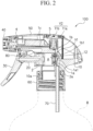
- Figure 2 is a side sectional view depicting the trigger sprayer according to the present embodiment.
- the trigger sprayer 100 has a base body 10, a piston portion 20 attached to a main cylinder portion 2 of the base body 10, a trigger 30 coupled to the piston portion 20 and pivotally attached to the base body 10, a first valve V1 and a second valve V2 incorporated in the base body 10 to control a flow of the liquid, a cover body 50 for covering the base body 10, a nozzle cap 40 attached to a nozzle portion 4 of the base body 10, a cap 60 for attaching the base body 10 to the container, and a tube 70 attached so as to communicate with a first flow path 1a of the base body 10.
- the trigger sprayer 100 is formed of the base body 10, the piston portion 20 attached to the base body 10, the trigger 30, the first valve V1, the second valve V2, the cover body 50, the nozzle cap 40, the cap 60, and the tube 70.
- the liquid in the container B is suctioned up via the tube 70 to the base body 10, flows inside the base body 10, and is ejected from the nozzle portion 4 of the base body 10 via the nozzle cap 40.
- the base body 10 is in an inverted L shape in side view. Note in the specification that a nozzle portion 4 side of the trigger sprayer 100 is taken as “front” and its opposite side is taken as "rear.
- a first flow path 1a where the liquid flows in a portion extending to an up-down direction, a main cylinder portion 2 communicated with the first flow path 1a to be able to store the liquid and a second flow path 1b communicated with the main cylinder portion 2 are provided.
- a sub-cylinder portion 3 communicated with the second flow path 1b, a third flow path 1c communicated with the sub-cylinder portion 3, and the nozzle portion 4 provided at a tip of the third flow path 1c are provided.
- the first flow path 1a extends to the up-down direction, and its lower end portion is in contact with the tube 70 so that their inner portions communicate with each other.
- first flow path 1a is provided with a first flow hole 1a1 on a side wall near its upper end portion. Via the first flow hole 1a1, the inner portion of the first flow path 1a and the inner portion of the main cylinder portion 2 (hereinafter also referred to "inner cylinder space A") communicate with each other.
- the second flow path 1b extends to the up-down direction, and has its upper end portion coupled to the sub-cylinder portion 3 so that their inner portions communicate with each other.
- the second flow path 1b is provided with a second flow hole 1b1 on a side wall near its lower end portion. Via the second flow hole 1b1, the inside of the second flow path 1b and the inner cylinder space A communicate with each other.
- the side wall provided with the first flow hole 1a1 and the side wall provided with the second flow hole 1b1 correspond to a bottom wall 2a of the main cylinder portion 2 (right-side wall of the main cylinder portion 2 in Figure 2 ).
- the first flow path 1a and the second flow path 1b extend to the up-down direction. Via the main cylinder portion 2, their inner portions communicate with each other.
- the main cylinder portion 2 is in a laterally-oriented cylindrical shape.
- the first valve V1 is attached in the main cylinder portion 2, so as to be in contact with its bottom wall 2a.
- the first valve V1 is a so-called check valve, and has a valve body 12 that opens and closes a connecting portion between the inner cylinder space A and the first flow hole 1a1.
- the piston portion 20 is attached to the main cylinder portion 2.
- the inner cylinder space A is in a state of being hermetically sealed by the piston portion 20.
- the piston portion 20 has its one end pivotally attached to a bulging portion of the arc-shaped trigger 30, and the trigger 30 has its upper end pivotally attached to a lower side of the third flow path 1c of the base body 10.
- the piston portion 20 When the trigger 30 is rotated as being pulled rearward with respect to the base body 10, the piston portion 20 is in conjunction with it to slide to a length direction (front-and-rear direction) of the main cylinder portion 2 along the inner wall of the main cylinder portion 2.
- the trigger 30 when the trigger 30 is released from a state of being pulled rearward, the trigger 30 is rotated so as to be returned to the original position by a spring 80 attached to the trigger 30.
- the third flow path 1c extends to the front-rear direction, and has its rear end portion coupled to the sub-cylinder portion 3 so that their inner portions communicate with each other.
- the third flow path 1c has its front end portion coupled to the nozzle portion 4 so that their inner portions communicate with each other.
- the sub-cylinder portion 3 is in a vertically-oriented cylindrical shape.
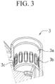
- Figure 3 is a perspective view depicting the inside of the trigger sprayer according to the present embodiment when its sub-cylinder portion is cut out in a vertical direction.
- the sub-cylinder portion 3 has its inner wall 3a provided with long groove portions 3b each recessed in a vertically elongated shape.
- the plurality of these long groove portions 3b are equidistantly provided in a circumferential direction of the inner wall 3a of the sub-cylinder portion 3.
- the inner capacity is large.
- the second valve V2 can abut on the inner wall 3a of the sub-cylinder portion 3 between the long groove portions 3b, but the second valve V2 cannot abut on bottom portions of the long groove portions 3b.
- a through hole 3c is provided at a position of each long groove portion 3b corresponding to the third flow path 1c. With this, the liquid flowing through the long groove portion 3b flows via the through hole 3c through the third flow path 1c.
- the sub-cylinder portion 3 has the second valve V2 arranged inside.
- the second valve V2 is arranged above the main cylinder portion 2.
- the sub-cylinder portion 3 is formed above the main cylinder portion 2.
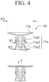
- Figure 4 is a side view depicting the second valve of the trigger sprayer according to the present embodiment.
- the second valve V2 has a second valve piston portion 11a slidable along the inner wall 3a of the sub-cylinder portion 3 and a dome spring portion 11b for pressing the second valve piston portion 11a downward.
- the dome spring portion 11b is in an inverted dome shape coupled to a core rod portion 11a3 of the second valve piston portion 11a.
- the dome spring portion 11b is elastically deformable.
- at least the dome spring portion 11b is manufactured of an elastically deformed material such as resin.
- the second valve piston portion 11a moves upward and downward based on elastic deformation of the dome spring portion 11b.
- the second valve piston portion 11a has the core rod portion 11a3, a bell-shaped inner skirt portion 11a2 coupled to the core rod portion 11a3 and provided on the circumference of the core rod portion 11a3, and a bell-shaped outer skirt portion 11a1 coupled to the core rod portion 11a3 and provided on the circumference of the inner skirt portion 11a2. Note that an air gap portion is provided between the core rod portion 11a3 and the inner skirt portion 11a2 and between the inner skirt portion 11a2 and the outer skirt portion 11a1. In the air gap portion, the liquid can be accommodated.
- a maximum diameter R1 of the outer skirt portion 11a1 and a maximum diameter R2 of the inner skirt portion 11a2 are equal.
- both of the outer skirt portion 11a1 and the inner skirt portion 11a2 simultaneously abut on the inner wall of the sub-cylinder portion 3.
- the dome spring portion 11b is in an inverted dome shape.
- the second valve piston portion 11a can be uniformly moved upward and downward without imbalances.
- a maximum diameter R3 of the dome spring portion 11b is larger than the diameters (R1, R2) of the inner skirt portion and the outer skirt portion of the second valve piston portion 11a, preferably 1.5 fold or more.
- a space in the up-down direction required for expansion and contraction of the second valve V2 can be made as small as possible.
- the nozzle portion 4 is, as described above, a portion provided at the front end portion of the third flow path 1c, the portion from which the liquid passing through the third flow path 1c is ejected.
- the nozzle cap 40 for protecting the nozzle portion 4 or providing another function is attached.
- the nozzle cap 40 has a function not particularly limited and can have a function of switching ON/OFF by rotation, a function of foaming or atomizing the liquid, and so forth.
- the cover body 50 is attached to cover the base body 10 so as to protect the base body 10.
- a support wall surface 5 on which the dome spring portion 11b abuts is provided.
- the trigger sprayer 100 by providing the support wall surface 5 by using the cover body 50, it is not required to separately provide the support wall surface 5 to the base body 10.
- the length of the base body 10 in the up-down direction can be shortened as much as possible.
- the cap 60 is attached to a lower end of the base body 10. This cap 60 can be screwed to a mouth portion of the container B.
- the cap 60 is attached to the container B by being screwed to the mouth portion of the container B.
- the base body 10 can be freely rotated with respect to the cap 60.
- a flange portion 10a formed at a lower end of the base body 10 is pinched between the cap 60 and the mouth portion of the container B, thereby causing the base body 10 to be fixed to the container B.
- Figure 5(a) is a side sectional view depicting a state in the course of rotating the trigger of the trigger sprayer according to the present embodiment rearward.
- Figure 5(b) is a side sectional view depicting a state in which, from the state depicted in Figure 5(a) , the trigger is completed to be rotated rearward and ejection of liquid is completed.
- Figure 5(c) is a side sectional view depicting a state, from the state depicted in Figure 5(b) , in the course of rotating the trigger forward.
- Figure 6 is a descriptive diagram for describing a state in the trigger sprayer according to the present embodiment in which the second valve is pushed up.
- the gap S is formed of the long groove portions 3b.
- the liquid (or air in an initial state) flows via the gap S through the third flow path 1c.
- the long groove portions 3b are provided in an inner wall 3a between positions where the outer skirt portion 11a1 abuts on the inner wall 3a of the sub-cylinder portion 3 and positions where the inner skirt portion 11a2 abuts on the inner wall 3a of the sub-cylinder portion 3.
- the liquid is caused to flow from below the inner skirt portion 11a2 in the sub-cylinder portion 3 via the long groove portions 3b (gap S) and the through hole 3c to the third flow path 1c.
- the flow is caused to pass through the long groove portion 3b not provided with through hole 3c to flow in between the inner skirt portion 11a2 and the outer skirt portion 11a1 and, from there, flow via the through hole 3c to the third flow path 1c.
- the liquid can be prevented from leaking.
- the liquid (or air in an initial state) flowing into the third flow path 1c is ejected outside from the nozzle portion 4 via the nozzle cap 40.
- the liquid can be prevented from dripping from the nozzle portion 4.
- the liquid is suctioned up from the container by that pressure, and flows via the tube 70 into the first flow path 1a.
- the liquid flowing into the first flow path 1a opens the check valve of the first valve V1, and flows into the inner cylinder space A of the main cylinder portion 2.
- the operation of the trigger can cause the liquid stored in the base body 10 to be ejected or cause ejection of the liquid to be stopped.
- the second valve V2 one having the second valve piston portion 11a and the elastically-deformable, inverted-dome-shaped dome spring portion 11b is adopted. Therefore, ejection responsiveness and ejection stability are excellent.
- the base body 10 has the piston portion 20, the trigger 30, the first valve V1, the second valve V2, the cover body 50, the nozzle cap 40, the cap 60, and the tube 70 attached thereto as separate bodies, but these may be integrally formed with the base body 10.
- cover body 50, the nozzle cap 40, the cap 60, and the tube 70 are not requisites.
- a check valve is adopted as the first valve V1, but this is not meant to be restrictive.
- the long groove portions 3b are provided in the inner wall 3a of the sub-cylinder portion 3, but the long-groove portions 3b are not requisites.
- the shape and number of the long groove portions 3b, the position where it is provided, and so forth are not particularly limited.
- the second valve piston portion 11a and the dome spring portion 11b are integrated, but they may be separable.
- the trigger sprayer according to the present invention can be used as a so-called accumulator trigger sprayer that suctions up liquid accommodated in the container, stores a certain amount of the liquid, and continuously ejects it.
- ejection responsiveness and ejection stability are excellent.
Landscapes
- Containers And Packaging Bodies Having A Special Means To Remove Contents (AREA)
- Closures For Containers (AREA)
Applications Claiming Priority (2)
| Application Number | Priority Date | Filing Date | Title |
|---|---|---|---|
| JP2020219863A JP7109811B2 (ja) | 2020-12-29 | 2020-12-29 | トリガースプレイヤー |
| PCT/JP2021/047552 WO2022145305A1 (ja) | 2020-12-29 | 2021-12-22 | トリガースプレイヤー |
Publications (2)
| Publication Number | Publication Date |
|---|---|
| EP4272873A1 true EP4272873A1 (de) | 2023-11-08 |
| EP4272873A4 EP4272873A4 (de) | 2024-11-13 |
Family
ID=82260440
Family Applications (1)
| Application Number | Title | Priority Date | Filing Date |
|---|---|---|---|
| EP21915165.1A Pending EP4272873A4 (de) | 2020-12-29 | 2021-12-22 | Trigger-sprühvorrichtung |
Country Status (5)
| Country | Link |
|---|---|
| US (1) | US20240066538A1 (de) |
| EP (1) | EP4272873A4 (de) |
| JP (1) | JP7109811B2 (de) |
| CN (1) | CN116710365A (de) |
| WO (1) | WO2022145305A1 (de) |
Family Cites Families (18)
| Publication number | Priority date | Publication date | Assignee | Title |
|---|---|---|---|---|
| FR2721285B1 (fr) * | 1994-06-20 | 1996-08-02 | Oreal | Pompe manuelle à précompression pour la pulvérisation d'un liquide et ensemble de distribution équipé d'une telle pompe. |
| US5622317A (en) * | 1994-12-12 | 1997-04-22 | Contico International, Inc. | Pressure buildup trigger sprayer |
| CA2184849A1 (en) * | 1995-09-27 | 1997-03-28 | Donald D. Foster | Liquid dispenser with trigger sprayer |
| IT1283712B1 (it) | 1996-03-29 | 1998-04-30 | Coster Tecnologie Speciali Spa | Dispositivo spruzzatore azionabile manualmente tramite leve grilletto. |
| US6116472A (en) * | 1998-12-15 | 2000-09-12 | Calmar Inc. | Trigger acutated pump sprayer |
| US6131820A (en) * | 1999-06-01 | 2000-10-17 | Calmar Inc. | Discharge valve assembly for trigger sprayer |
| ITMI20030080A1 (it) * | 2003-01-21 | 2004-07-22 | Spray Plast Spa | Dispositivo spruzzatore semplificato. |
| US20060289679A1 (en) * | 2005-06-27 | 2006-12-28 | Johnson Kaj A | Modular sprayer |
| US7497358B2 (en) * | 2006-03-15 | 2009-03-03 | Meadwestvaco Calmar, Inc. | Trigger sprayer with integral piston rod and bowed spring |
| JP2007289840A (ja) | 2006-04-24 | 2007-11-08 | Canyon Corp | スポイド式ポンプディスペンサ |
| JP6057597B2 (ja) | 2011-08-12 | 2017-01-11 | キャニヨン株式会社 | 蓄圧式トリガースプレイヤー及びその蓄圧バルブ |
| ITMI20112168A1 (it) | 2011-11-28 | 2013-05-29 | Mwv Vicenza S P A | Spruzzatore per liquidi con camera di precompressione |
| JP6258128B2 (ja) * | 2014-05-30 | 2018-01-10 | 株式会社吉野工業所 | トリガー式液体噴出器 |
| JP6345095B2 (ja) | 2014-06-30 | 2018-06-20 | 株式会社吉野工業所 | トリガー式液体噴出器 |
| JP6723062B2 (ja) * | 2016-04-25 | 2020-07-15 | キャニヨン株式会社 | トリガースプレイヤ |
| JP6833361B2 (ja) * | 2016-06-24 | 2021-02-24 | キャニヨン株式会社 | 蓄圧式スプレー |
| JP6803724B2 (ja) | 2016-10-31 | 2020-12-23 | 株式会社吉野工業所 | トリガー式液体噴出器 |
| CN111924318B (zh) * | 2020-09-08 | 2025-03-14 | 广东美捷时控股股份有限公司 | 一种全塑型手枪喷雾泵 |
-
2020
- 2020-12-29 JP JP2020219863A patent/JP7109811B2/ja active Active
-
2021
- 2021-12-22 WO PCT/JP2021/047552 patent/WO2022145305A1/ja not_active Ceased
- 2021-12-22 US US18/259,396 patent/US20240066538A1/en active Pending
- 2021-12-22 EP EP21915165.1A patent/EP4272873A4/de active Pending
- 2021-12-22 CN CN202180087630.5A patent/CN116710365A/zh active Pending
Also Published As
| Publication number | Publication date |
|---|---|
| JP7109811B2 (ja) | 2022-08-01 |
| EP4272873A4 (de) | 2024-11-13 |
| WO2022145305A1 (ja) | 2022-07-07 |
| JP2022104727A (ja) | 2022-07-11 |
| US20240066538A1 (en) | 2024-02-29 |
| CN116710365A (zh) | 2023-09-05 |
Similar Documents
| Publication | Publication Date | Title |
|---|---|---|
| US4230242A (en) | Triple seal valve member for an atomizing pump dispenser | |
| KR870001170B1 (ko) | 액체분배펌프 | |
| US4735347A (en) | Single puff atomizing pump dispenser | |
| US9365408B2 (en) | Auto refill perfume atomizer | |
| US6131820A (en) | Discharge valve assembly for trigger sprayer | |
| US10525493B2 (en) | Pump for a receptacle, in particular a bottle for a cosmetic product, and a dispensing device comprising such a pump | |
| CZ142797A3 (cs) | Vydávací zařízení pro kapalné látky | |
| EP2190758A1 (de) | Ventil zur verwendung in einem behälter, der druck zur abgabe von produkten einsetzt | |
| FI90739C (fi) | Kuristamaton poistopumppukokoonpano | |
| JPH04225858A (ja) | 噴霧ポンプ | |
| IT8448337A1 (it) | Pompa erogatrice atta al riempimento a pressione | |
| CN118159740A (zh) | 具有双作用活塞的触发式喷射器组件 | |
| US8210400B2 (en) | Valve for use in a container which employs pressure to dispense product | |
| JP5095357B2 (ja) | ポンプ及びそれに取付ける容器 | |
| US10279362B2 (en) | Auto refill perfume atomizer apparatus | |
| EP4272873A1 (de) | Trigger-sprühvorrichtung | |
| EP3503792B1 (de) | Langzeitsprühvorrichtung mit inline-vakuumfeder | |
| JP2023097140A (ja) | 吐出器 | |
| US20080251541A1 (en) | Fluid Product Dispenser | |
| JP4554342B2 (ja) | 蓄圧式二液噴霧器 | |
| EP4118987B1 (de) | Zerstäuber | |
| US12485440B2 (en) | S valve structure for accumulator spray | |
| US20260061441A1 (en) | Discharge head and fluid dispenser with such a discharge head | |
| EP4516409A1 (de) | Druckakkumulierende sprühvorrichtung | |
| JP2025007063A (ja) | 吐出器 |
Legal Events
| Date | Code | Title | Description |
|---|---|---|---|
| STAA | Information on the status of an ep patent application or granted ep patent |
Free format text: STATUS: THE INTERNATIONAL PUBLICATION HAS BEEN MADE |
|
| PUAI | Public reference made under article 153(3) epc to a published international application that has entered the european phase |
Free format text: ORIGINAL CODE: 0009012 |
|
| STAA | Information on the status of an ep patent application or granted ep patent |
Free format text: STATUS: REQUEST FOR EXAMINATION WAS MADE |
|
| 17P | Request for examination filed |
Effective date: 20230620 |
|
| AK | Designated contracting states |
Kind code of ref document: A1 Designated state(s): AL AT BE BG CH CY CZ DE DK EE ES FI FR GB GR HR HU IE IS IT LI LT LU LV MC MK MT NL NO PL PT RO RS SE SI SK SM TR |
|
| DAV | Request for validation of the european patent (deleted) | ||
| DAX | Request for extension of the european patent (deleted) | ||
| A4 | Supplementary search report drawn up and despatched |
Effective date: 20241016 |
|
| RIC1 | Information provided on ipc code assigned before grant |
Ipc: B65D 47/34 20060101ALI20241010BHEP Ipc: B05B 11/00 20230101AFI20241010BHEP |