EP4273370B1 - Turbinenringanordnung zur differentiellen thermischen ausdehnung - Google Patents
Turbinenringanordnung zur differentiellen thermischen ausdehnung Download PDFInfo
- Publication number
- EP4273370B1 EP4273370B1 EP23198187.9A EP23198187A EP4273370B1 EP 4273370 B1 EP4273370 B1 EP 4273370B1 EP 23198187 A EP23198187 A EP 23198187A EP 4273370 B1 EP4273370 B1 EP 4273370B1
- Authority
- EP
- European Patent Office
- Prior art keywords
- ring
- support structure
- sectors
- annular
- turbine
- Prior art date
- Legal status (The legal status is an assumption and is not a legal conclusion. Google has not performed a legal analysis and makes no representation as to the accuracy of the status listed.)
- Active
Links
Images




Classifications
-
- F—MECHANICAL ENGINEERING; LIGHTING; HEATING; WEAPONS; BLASTING
- F01—MACHINES OR ENGINES IN GENERAL; ENGINE PLANTS IN GENERAL; STEAM ENGINES
- F01D—NON-POSITIVE DISPLACEMENT MACHINES OR ENGINES, e.g. STEAM TURBINES
- F01D11/00—Preventing or minimising internal leakage of working-fluid, e.g. between stages
- F01D11/08—Preventing or minimising internal leakage of working-fluid, e.g. between stages for sealing space between rotor blade tips and stator
-
- F—MECHANICAL ENGINEERING; LIGHTING; HEATING; WEAPONS; BLASTING
- F01—MACHINES OR ENGINES IN GENERAL; ENGINE PLANTS IN GENERAL; STEAM ENGINES
- F01D—NON-POSITIVE DISPLACEMENT MACHINES OR ENGINES, e.g. STEAM TURBINES
- F01D25/00—Component parts, details, or accessories, not provided for in, or of interest apart from, other groups
- F01D25/005—Selecting particular materials
-
- F—MECHANICAL ENGINEERING; LIGHTING; HEATING; WEAPONS; BLASTING
- F01—MACHINES OR ENGINES IN GENERAL; ENGINE PLANTS IN GENERAL; STEAM ENGINES
- F01D—NON-POSITIVE DISPLACEMENT MACHINES OR ENGINES, e.g. STEAM TURBINES
- F01D25/00—Component parts, details, or accessories, not provided for in, or of interest apart from, other groups
- F01D25/24—Casings; Casing parts, e.g. diaphragms, casing fastenings
-
- F—MECHANICAL ENGINEERING; LIGHTING; HEATING; WEAPONS; BLASTING
- F01—MACHINES OR ENGINES IN GENERAL; ENGINE PLANTS IN GENERAL; STEAM ENGINES
- F01D—NON-POSITIVE DISPLACEMENT MACHINES OR ENGINES, e.g. STEAM TURBINES
- F01D25/00—Component parts, details, or accessories, not provided for in, or of interest apart from, other groups
- F01D25/24—Casings; Casing parts, e.g. diaphragms, casing fastenings
- F01D25/246—Fastening of diaphragms or stator-rings
-
- F—MECHANICAL ENGINEERING; LIGHTING; HEATING; WEAPONS; BLASTING
- F05—INDEXING SCHEMES RELATING TO ENGINES OR PUMPS IN VARIOUS SUBCLASSES OF CLASSES F01-F04
- F05D—INDEXING SCHEME FOR ASPECTS RELATING TO NON-POSITIVE-DISPLACEMENT MACHINES OR ENGINES, GAS-TURBINES OR JET-PROPULSION PLANTS
- F05D2230/00—Manufacture
- F05D2230/60—Assembly methods
- F05D2230/64—Assembly methods using positioning or alignment devices for aligning or centring, e.g. pins
- F05D2230/642—Assembly methods using positioning or alignment devices for aligning or centring, e.g. pins using maintaining alignment while permitting differential dilatation
-
- F—MECHANICAL ENGINEERING; LIGHTING; HEATING; WEAPONS; BLASTING
- F05—INDEXING SCHEMES RELATING TO ENGINES OR PUMPS IN VARIOUS SUBCLASSES OF CLASSES F01-F04
- F05D—INDEXING SCHEME FOR ASPECTS RELATING TO NON-POSITIVE-DISPLACEMENT MACHINES OR ENGINES, GAS-TURBINES OR JET-PROPULSION PLANTS
- F05D2240/00—Components
- F05D2240/10—Stators
- F05D2240/11—Shroud seal segments
-
- F—MECHANICAL ENGINEERING; LIGHTING; HEATING; WEAPONS; BLASTING
- F05—INDEXING SCHEMES RELATING TO ENGINES OR PUMPS IN VARIOUS SUBCLASSES OF CLASSES F01-F04
- F05D—INDEXING SCHEME FOR ASPECTS RELATING TO NON-POSITIVE-DISPLACEMENT MACHINES OR ENGINES, GAS-TURBINES OR JET-PROPULSION PLANTS
- F05D2300/00—Materials; Properties thereof
- F05D2300/60—Properties or characteristics given to material by treatment or manufacturing
- F05D2300/603—Composites; e.g. fibre-reinforced
- F05D2300/6033—Ceramic matrix composites [CMC]
Definitions
- a turbine ring assembly comprising a plurality of ring sectors made of ceramic matrix composite material and a ring support structure is disclosed.
- CMC materials have good mechanical properties making them suitable for use in structural elements and advantageously retain these properties at high temperatures.
- the use of CMC materials has advantageously made it possible to reduce the cooling flow required during operation and therefore to increase the performance of turbomachines.
- the use of CMC materials advantageously makes it possible to reduce the mass of turbomachines and to reduce the effect of hot expansion encountered with metal parts.
- the existing solutions proposed may implement an assembly of a CMC ring sector with metal attachment parts of a ring support structure, these attachment parts being subjected to the hot flow. Consequently, these metal attachment parts undergo hot expansions, which may lead to mechanical stressing of the CMC ring sectors and their embrittlement.
- a turbine ring assembly comprising a plurality of ring sectors made of ceramic matrix composite material forming a turbine ring and a ring support structure, each ring sector having an annular base portion with an inner face defining the inner face of the turbine ring and an outer face from which extends a portion for attaching the ring sector to the ring support structure, the ring support structure comprising two annular flanges between which the attachment portion of each ring sector is held, the annular flanges of the ring support structure each having at least one inclined portion bearing on the attachment portions of the ring sectors, said inclined portion forming, when observed in meridian section, a non-zero angle relative to the radial direction and to the axial direction, characterized in that the attachment portions of the ring sectors are held to the ring support structure at axial portions each extending parallel to the axial direction, these axial portions being formed by a plurality of added elements engaged without play when cold through the annular f
- the radial direction corresponds to the direction along a radius of the turbine ring (straight line connecting the center of the turbine ring to its periphery).
- the axial direction corresponds to the direction along the axis of revolution of the turbine ring as well as the direction of flow of the gas flow in the vein.
- At least one of the flanges of the ring support structure is elastically deformable.
- This advantageously makes it possible to compensate even better for differential expansions between the attachment portions of the CMC ring sectors and the flanges of the metal ring support structure without significantly increasing the stress exerted "when cold" by the flanges on the attachment portions of the ring sectors.
- both flanges of the ring support structure are elastically deformable or only one of the two flanges of the ring support structure is elastically deformable.
- each of the annular flanges of the ring support structure may have a first and a second inclined portion bearing on the attachment parts of the ring sectors, said first and second inclined portions each forming, when observed in meridian section, a non-zero angle relative to the radial direction and to the axial direction.
- the patent further describes the case where the first inclined portion may bear on the upper half of the attachment parts of the ring sectors and the second inclined portion may bear on the lower half of the attachment parts of the ring sectors.
- the upper half of a hooking portion of a ring sector corresponds to the portion of said hooking portion extending radially between the mid-length zone of the hooking portion and the end of the hooking portion located on the side of the ring support structure.
- the lower half of a hooking portion of a ring sector corresponds to the portion of the hooking portion extending radially between the mid-length zone of the hooking portion and the end of the hooking portion located on the side of the annular base.
- the ring support structure has axial portions bearing on the attachment parts of the ring sectors, the axial portions each extending parallel to the axial direction, these axial portions being formed by a plurality of inserts engaged without cold play through the annular flanges.
- the hooking parts of the ring sectors are held to the ring support structure at such axial portions.
- the annular flanges of the ring support structure may grip the hooking portions of the ring sectors over at least half the length of said hooking portions.
- the annular flanges of the ring support structure may grip the attachment portions of the ring sectors at least at the outer radial ends of said attachment portions.
- the outer radial end of a attachment portion corresponds to the end of this attachment portion located on the side opposite the flow path of the gas flow.
- the annular flanges of the ring support structure may grip the attachment portions of the ring sectors only at the upper half of said attachment portions.
- each ring sector may be in the form of radially extending tabs.
- the outer radial ends of the tabs of the ring sectors may not be in contact and the tabs of the ring sectors may define between them an interior ventilation volume for each of the ring sectors.
- the attachment portion of each of the ring sectors is in the form of a bulb.
- the ring sectors have a substantially ⁇ -shaped or substantially ⁇ -shaped section.
- the present invention also relates to a turbomachine comprising a turbine ring assembly as described above.
- the turbine ring assembly may be part of a gas turbine of an aero engine or may alternatively be part of an industrial turbine.
- upstream and downstream are used here in reference to the direction of flow of the gas stream in the turbine (see arrow F in Figure 1 , For example).
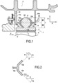
- FIG. 1 which is outside the invention, shows a turbine ring sector 1 and a casing 2 made of metallic material constituting a ring support structure.
- the ring support structure 2 is made of a metallic material such as the Waspaloy ® alloy or the Inconel ® 718 alloy.
- the set of ring sectors 1 is mounted on the casing 2 so as to form a turbine ring which surrounds a set of rotating blades 3.
- the arrow F represents the direction of flow of the gas flow in the turbine.
- the ring sectors 1 are in a single piece and made of CMC. The use of a CMC material to make the ring sectors 1 is advantageous in order to reduce the ventilation requirements of the ring.
- the ring sectors 1 have, in the example illustrated, a substantially ⁇ -shaped section with an annular base 5 whose radially internal face 6 is coated with a layer 7 of material abradable defines the flow path of the gas flow in the turbine.
- the annular base 5 further has a radially external face 8 from which a hooking portion 9 extends.
- the hooking portion 9 is in the form of a solid bulb; it does not depart from the scope of the invention when the hooking portion is in the form of a hollow bulb or when the latter is in another form as detailed below.
- the inter-sector seal is ensured by sealing tabs (not shown) housed in grooves facing each other in the edges opposite two neighboring ring sectors.
- Each ring sector 1 described above is made of CMC by forming a fiber preform having a shape close to that of the ring sector and densifying the ring sector with a ceramic matrix.
- ceramic fiber yarns may be used, for example SiC fiber yarns such as those marketed by the Japanese company Nippon Carbon under the name "Nicalon", or carbon fiber yarns.
- the fiber preform is advantageously made by three-dimensional weaving, or multi-layer weaving. The weaving may be of the interlock type. Other three-dimensional or multi-layer weaving weaves may be used, such as multi-plain or multi-satin weaves. For this purpose, reference may be made to the document WO 2006/136755 .
- the blank can be shaped to obtain a ring sector preform which is then consolidated and densified by a ceramic matrix, the densification being able to be carried out in particular by chemical gas infiltration (CVI) which is well known in itself.
- CVI chemical gas infiltration
- the casing 2 comprises two annular radial flanges 11a and 11b made of metallic material extending radially towards a flow vein of the gas flow.
- the annular flanges 11a and 11b of the casing 2 axially enclose the attachment parts 9 of the ring sectors 1.
- the hooking parts 9 of the ring sectors 1 are held between the annular flanges 11a and 11b, the hooking parts 9 being housed between the annular flanges 11a and 11b.
- ventilation orifices 34 formed in the flange 11a allows cooling air to be brought to the outer side of the turbine ring 1.
- the annular flanges 11a and 11b each have two inclined portions resting on the attachment parts 9 of the ring sectors 1 and ensuring their retention.
- the inclined portions of the annular flanges 11a and 11b are in contact with the attachment parts 9 of the ring sectors 1.
- the upstream annular flange 11a has a first inclined portion 12a and a second inclined portion 13a.
- the flange 11a also has a third portion 15a extending in the radial direction R and located between the first 12a and the second 13a inclined portion.
- the downstream annular flange 11b also has a first inclined portion 12b and a second inclined portion 13b.
- the flange 11b also has a third portion 15b extending in the radial direction R and located between the first 12b and the second 13b inclined portion.
- the first inclined portion 12a of the upstream annular flange 11a forms a non-zero angle ⁇ 1 with the radial direction R and forms a non-zero angle ⁇ 2 with the axial direction A.
- the second inclined portion 13a of the upstream annular flange 11a forms a non-zero angle ⁇ 3 with the radial direction R and forms a non-zero angle ⁇ 4 with the axial direction A.
- first and second inclined portions 12b and 13b of the downstream annular flange 11b The same is true for the first and second inclined portions 12a and 13a of the downstream annular flange 11b.
- the first and second inclined portions 12a and 13a extend in non-parallel directions (they form a non-zero angle between them).
- the inclined portions of the annular flanges 11a and 11b extend at a non-zero angle with the radial direction R and a non-zero angle with the axial direction A.
- the inclined portions of the annular flanges 11a and 11b each extend in a straight line.
- the inclined portions 12a, 12b, 13a, and 13b each have an elongated shape.
- all or part of the inclined portions of the annular flanges 11a and 11b may form an angle of between 30° and 60° with the radial direction.
- the angle formed between its first inclined portion and the radial direction may or may not be equal to the angle formed between its second inclined portion and the radial direction, when the first and second inclined portions are observed in meridian section.
- the annular flanges 11a and 11b enclose the attachment parts 9 of the ring sectors over more than half of the length l of said attachment parts 9, in particular over at least 75% of this length.
- the length l is measured in the radial direction R.
- the first inclined portions 12a and 12b are, when observed in meridian section, each resting on the upper half M 1 of the hooking parts 9 and the second inclined portions 13a and 13b are, when observed in meridian section, each resting on the lower half M 2 of the hooking parts 9.
- the upper half M 1 corresponds to the portion of the hooking part 9 extending radially between the zone Z at mid-length of the hooking part 9 and the end E 1 of the hooking part located on the side of the ring support structure 2 (external radial end).
- the lower half M 2 corresponds to the portion of the hooking part 9 extending radially between the zone Z at mid-length of the hooking part 9 and the end E 2 of the hooking part located on the side of the annular base 5 (internal radial end).
- the inclined portions of the annular flanges 11a and 11b define two hooks between which the hooking portions 9 of the ring sectors 1 are axially clamped.
- Each of these hooks has, in the example illustrated, substantially a C shape.
- the implementation of the inclined portions advantageously makes it possible to compensate for the differences in expansion between the annular flanges 11a and 11b, on the one hand, and the ring sectors 1, on the other hand, and thus to reduce the mechanical stresses to which the ring sectors 1 are subjected during operation.
- annular flanges flange 11b at the Figure 1
- hook 25 whose function will be detailed later.
- the maintenance of the ring sectors 1 to the ring support structure 2 is ensured solely by the annular flanges 11a and 11b (no presence of an element reported such as a pin through the attachment part 9 of the ring sectors).
- the exemplary embodiments of the invention implement such reported elements in order to participate in maintaining the ring sectors on the ring support structure.
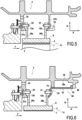
- the attachment part of the ring sectors 1a is in the form of lugs 9a and 9b extending radially from the external face 8 of the annular base 5.
- the external radial ends 10a and 10b of the lugs 9a and 9b of the ring sectors 1a are not in contact.
- the external radial end of a lug of a ring sector corresponds to the end of said lug located on the side opposite the flow path of the gas flow.
- the external radial ends 10a and 10b are, in the example illustrated in Figure 3 , spaced along the axial direction A.
- the legs 9a and 9b of the ring sectors define between them an interior ventilation volume V for each of the ring sectors 1a. It is thus possible to ventilate the ring sectors 1a by sending cooling air towards their annular base 5 through the ventilation orifice 14 defined between the legs 9a and 9b.
- the 1a ring sectors of the Figure 3 substantially have an open ⁇ shape at its end located on the side of the ring support structure 2.
- the fiber preform intended to form the ring sector 1a of the type illustrated in the Figure 3 can be produced by three-dimensional weaving, or multi-layer weaving with the provision of decoupling zones making it possible to separate the parts of preforms corresponding to the legs 9a and 9b from the part of preform corresponding to the base 5.
- the parts of preforms corresponding to the legs can be produced by weaving layers of threads passing through the part of preform corresponding to the base 5.
- each of the annular flanges 21a and 21b have a single inclined portion 13a or 13b bearing on the lugs 19a or 19b of the ring sectors 1b and forming a non-zero angle relative to the radial direction R and to the axial direction A.
- the axial portions 16a and 16b bear on the lugs 19a and 19b of the ring sectors.
- the lugs 19a and 19b forming the attachment part of the ring sectors 1b are held to the ring support structure 2 at the axial portions 16a and 16b.
- the axial portions 16a and 16b formed by the annular flanges block the movement of the ring sectors 1b outwards in the radial direction R.
- the annular flanges 21a and 21b axially enclose the legs 19a and 19b of the ring sectors 1b at their external radial end 20a and 20b.
- the inclined portion and the axial portion form for each of the annular flanges 21a and 21b a hook bearing on the legs 19a and 19b of the ring sectors 1b.
- the legs 19a and 19b of the ring sectors 1b are axially enclose between these two hooks formed by the annular flanges 21a and 21b.
- the ring sectors 1b have a section that is substantially ⁇ -shaped.
- the pins 35 each pass through a hole provided in the annular upstream radial flange 31a and a hole provided in each upstream tab 29a, the holes in the flange 31a and the tabs 29a being aligned when the ring sectors 1c are mounted on the ring support structure 2.
- pins 37 are engaged both in the annular downstream radial flange 31b of the ring support structure 2 and in the downstream tabs 29b of the ring sectors 1c.
- the pins 37 each pass through an orifice provided in the annular downstream radial flange 31b and an orifice provided in each downstream tab 29b, the orifices of the flange 31b and the tabs 29b being aligned when mounting the ring sectors 1c on the ring support structure 2.
- the pins 35 and 37 are engaged without play when cold through the flanges 31a and 31b and the lugs 29a and 29b.
- the pins 35 and 37 make it possible to lock the ring sectors 1c in rotation.
- the pins 35 and 37 block the movement of the ring sectors 1c inward and outward in the radial direction R.
- the annular flanges 31a and 31b each further have a single inclined portion 13a or 13b making it possible to reduce the stress applied to the ring sectors 1c during the expansion of the annular flanges 31a and 31b during operation.
- each ring sector 1c has a substantially ⁇ -shaped section with an annular base 5 whose internal face coated with a layer 7 of abradable material defines the gas flow stream in the turbine.
- Upstream and downstream legs 29a and 29b extend from the external face of the annular base 5 in the radial direction R.
- the ring support structure 2 is, in this exemplary embodiment, formed of two parts, namely a first part corresponding to an annular upstream radial flange 31a which is preferably formed integrally with a turbine casing and a second part corresponding to an annular retention flange 50 mounted on the turbine casing.
- the annular upstream radial flange 31a comprises an inclined portion 13a as described above bearing on the upstream legs 29a of the ring sectors 1c.
- the flange 50 comprises an annular web 57 which forms an annular downstream radial flange 54 comprising an inclined portion 13b as described above bearing on the downstream legs 29b of the ring sectors 1c.
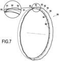
- the flange 50 comprises an annular body 51 extending axially and comprising, on the upstream side, the annular web 57 and, on the downstream side, a first series of teeth 52 distributed circumferentially on the flange 50 and spaced from each other by first engagement passages 53 ( Figure 7 ).
- the turbine casing has on the downstream side a second series of teeth 60 extending radially from the inner surface 38a of the shell 38 of the turbine casing.
- the teeth 60 are distributed circumferentially on the inner surface 38a of the shell 38 and spaced from each other by second engagement passages 61 ( figure 13 ). Teeth 52 and 60 cooperate with each other to form a circumferential dog clutch.
- each ring sector 1c are mounted in prestress between the annular flanges 31a and 54 so that the flanges exert, at least when “cold”, i.e. at an ambient temperature of approximately 25°C, a stress on the legs 29a and 29b. Furthermore, as in the exemplary embodiment of the Figure 5 , ring sectors 1c are further held by blocking pins 35 and 37.
- At least one of the flanges of the ring support structure is elastically deformable, which makes it possible to further compensate for differential expansions between the legs of the CMC ring sectors and the flanges of the metal ring support structure without significantly increasing the stress exerted "when cold" by the flanges on the legs of the ring sectors.
- annular boss 70 extending radially from the internal surface 38a of the shell 38 of the turbine casing and the free end of which is in contact with the surface of the body 51 of the flange 50.
- the spacing E between the annular upstream radial flange 31a and the annular downstream radial flange 31b at “rest”, that is to say when no ring sector is mounted between the flanges, is less than the distance D present between the external faces 29c and 29d of the upstream and downstream legs 29a and 29b of the ring sectors.
- the spacing E is measured between the ends of the inclined portions 13a and 13b of the annular flanges 31a and 31b.
- the ring support structure comprises at least one annular flange which is elastically deformable in the axial direction A of the ring.
- the annular downstream radial flange 31b is elastically deformable.
- the annular downstream radial flange 31b is pulled in the axial direction A as shown in the figures 9 And 10 in order to increase the spacing between the flanges 31a and 31b and allow the insertion of the tabs 29a and 29b between the flanges 31a and 31b without risk of damage.
- the flange 31b is released in order to hold the ring sector.
- the latter comprises a plurality of hooks 25 distributed on its face 31c, face which is opposite the face 31d of the flange 31b opposite the downstream tabs 29b of the ring sectors 1c.
- the traction in the axial direction A of the ring exerted on the elastically deformable flange 31b is here carried out by means of a tool 250 comprising at least one arm 251 whose end comprises a hook 252 which is engaged in the hook 25 present on the external face 31c of the flange 31b.
- the number of hooks 25 distributed on the face 31c of the flange 31b is defined as a function of the number of traction points that one wishes to have on the flange 31b. This number depends mainly on the elastic character of the flange. Other shapes and arrangements of means making it possible to exert traction in the axial direction A on one of the flanges of the ring support structure can of course be envisaged.
- each ring sector tab 29a or 29b may comprise one or more orifices for the passage of a locking pin.
- the ring sectors 1c are first fixed by their upstream tab 29a to the annular upstream radial flange 31a of the ring support structure 2 by pins 35 which are engaged in the aligned orifices 35b and 35a provided respectively in the annular upstream radial flange 31a and in the upstream tab 29a.
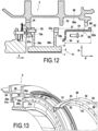
- the annular retention flange 50 is assembled by dog-engaging between the turbine casing and the downstream tabs of the ring sectors 29b.
- the spacing E' between the annular downstream radial flange 54 formed by the annular web 57 of the flange 50 and the external surface 52a of the teeth 52 of said flange is greater than the distance D' present between the external face 29d of the downstream tabs 29b of the ring sectors and the internal face 60a of the teeth 60 present on the turbine casing.
- the ring support structure comprises at least one annular flange which is elastically deformable in the axial direction A of the ring.
- it is the annular downstream radial flange 54 present on the flange 50 which is elastically deformable.
- the annular web 57 forming the annular downstream radial flange 54 of the ring support structure 2 has a reduced thickness compared to the annular upstream radial flange 31a, which gives it a certain elasticity.
- the flange 50 is mounted on the turbine casing by placing the teeth 52 present on the flange 50 opposite the engagement passages 61 provided on the turbine casing, the teeth 60 present on said turbine casing also being placed opposite the engagement passages 53 provided between the teeth 52 on the flange 50.
- the spacing E' being greater than the distance D', it is necessary to apply an axial force on the flange 50 in the direction indicated on the Figure 14 in order to engage the teeth 52 beyond the teeth 60 and allow a rotation R' of the flange at an angle corresponding substantially to the width of the teeth 60 and 52. After this rotation, the flange 50 is released, the latter then being maintained in axial constraint between the downstream legs 29b of the ring sectors and the internal surface 60a of the teeth 60 of the turbine casing.
- pins 37 are engaged in the aligned orifices 56 and 37a provided respectively in the annular downstream radial flange 54 and in the downstream lug 29b.
- Each ring sector lug 29a or 29b may comprise one or more orifices for the passage of a locking pin.
Landscapes
- Engineering & Computer Science (AREA)
- Mechanical Engineering (AREA)
- General Engineering & Computer Science (AREA)
- Chemical & Material Sciences (AREA)
- Materials Engineering (AREA)
- Turbine Rotor Nozzle Sealing (AREA)
- Structures Of Non-Positive Displacement Pumps (AREA)
Claims (8)
- Turbinenringanordnung, umfassend eine Vielzahl von Ringsektoren (1b; 1c) aus einem Verbundmaterial mit keramischer Matrix, die einen Turbinenring und eine Ringstützstruktur (2) bilden, wobei jeder Ringsektor (1b; 1c) einen ringförmigen Basisabschnitt (5) mit einer Innenfläche (6), die die Innenfläche des Turbinenrings definiert, und einer Außenfläche (8) aufweist, von der sich ein Einhängeteil (19a; 19b; 29a; 29b) des Ringsektors an der Ringstützstruktur erstreckt, wobei die Ringstützstruktur (2) zwei ringförmige Flansche (21a; 21b; 31a; 31b; 50) umfasst, zwischen denen der Einhängeteil jedes Ringsektors gehalten wird, wobei die ringförmigen Flansche der Ringstützstruktur jeweils mindestens einen geneigten Abschnitt (12a; 12b; 13a; 13b) aufweisen, der an den Einhängeteilen der Ringsektoren anliegt, wobei der geneigte Abschnitt, wenn er im Meridianschnitt betrachtet wird, einen Winkel ungleich Null in Bezug auf die radiale Richtung (R) und die axiale Richtung (A) bildet,
dadurch gekennzeichnet, dass die Einhängeteile (19a; 19b; 29a; 29b) der Ringsektoren (1b; 1c) an der Ringstützstruktur (2) im Bereich axialer Abschnitte (16a; 16b) gehalten werden, die sich jeweils parallel zur axialen Richtung erstrecken, wobei diese axialen Abschnitte von einer Vielzahl von Einsätzen (35; 37) gebildet werden, die ohne Kaltspiel durch die ringförmigen Flansche hindurch in Eingriff stehen. - Anordnung nach Anspruch 1, wobei die ringförmigen Flansche (11a; 11b) der Ringstützstruktur (2) die Einhängeteile (9) der Ringsektoren (1) über mindestens die Hälfte der Länge ℓ der Einhängeteile (9) umschließen.
- Anordnung nach Anspruch 1 oder 2, wobei die ringförmigen Flansche (21a; 21b) der Ringstützstruktur (2) die Einhängeteile (19a; 19b) der Ringsektoren (1b) zumindest im Bereich der äußeren radialen Enden (20a; 20b) der Einhängeteile (19a; 19b) umschließen.
- Anordnung nach einem der Ansprüche 1 bis 3, wobei der Einhängeteil jedes Ringsektors in Form von sich radial erstreckenden Laschen (9a; 9b; 19a; 19b; 29a; 29b) vorliegt.
- Anordnung nach Anspruch 4, wobei die äußeren radialen Enden (10a; 10b; 20a; 20b) der Laschen der Ringsektoren nicht in Kontakt sind und wobei die Laschen der Ringsektoren zwischen sich ein inneres Volumen (V) zur Belüftung für jeden der Ringsektoren definieren.
- Anordnung nach einem der Ansprüche 1 bis 3, wobei der Einhängeabschnitt jedes der Ringsektoren in Form einer Knolle (9) vorliegt.
- Anordnung nach einem der Ansprüche 1 bis 6, wobei die Ringsektoren einen im Wesentlichen Ω-förmigen oder im Wesentlichen n-förmigen Querschnitt haben.
- Turbomaschine, umfassend eine Turbinenringanordnung nach einem der Ansprüche 1 bis 7.
Applications Claiming Priority (3)
| Application Number | Priority Date | Filing Date | Title |
|---|---|---|---|
| FR1554626A FR3036435B1 (fr) | 2015-05-22 | 2015-05-22 | Ensemble d'anneau de turbine |
| PCT/FR2016/051168 WO2016189223A1 (fr) | 2015-05-22 | 2016-05-18 | Ensemble d'anneau de turbine. |
| EP16726369.8A EP3298246B1 (de) | 2015-05-22 | 2016-05-18 | Turbinenringanordnung, die eine unterschiedliche wärmeausdehnung erlaubt |
Related Parent Applications (2)
| Application Number | Title | Priority Date | Filing Date |
|---|---|---|---|
| EP16726369.8A Division EP3298246B1 (de) | 2015-05-22 | 2016-05-18 | Turbinenringanordnung, die eine unterschiedliche wärmeausdehnung erlaubt |
| EP16726369.8A Division-Into EP3298246B1 (de) | 2015-05-22 | 2016-05-18 | Turbinenringanordnung, die eine unterschiedliche wärmeausdehnung erlaubt |
Publications (3)
| Publication Number | Publication Date |
|---|---|
| EP4273370A2 EP4273370A2 (de) | 2023-11-08 |
| EP4273370A3 EP4273370A3 (de) | 2024-02-14 |
| EP4273370B1 true EP4273370B1 (de) | 2025-04-30 |
Family
ID=53879645
Family Applications (2)
| Application Number | Title | Priority Date | Filing Date |
|---|---|---|---|
| EP23198187.9A Active EP4273370B1 (de) | 2015-05-22 | 2016-05-18 | Turbinenringanordnung zur differentiellen thermischen ausdehnung |
| EP16726369.8A Active EP3298246B1 (de) | 2015-05-22 | 2016-05-18 | Turbinenringanordnung, die eine unterschiedliche wärmeausdehnung erlaubt |
Family Applications After (1)
| Application Number | Title | Priority Date | Filing Date |
|---|---|---|---|
| EP16726369.8A Active EP3298246B1 (de) | 2015-05-22 | 2016-05-18 | Turbinenringanordnung, die eine unterschiedliche wärmeausdehnung erlaubt |
Country Status (8)
| Country | Link |
|---|---|
| US (2) | US10724401B2 (de) |
| EP (2) | EP4273370B1 (de) |
| CN (2) | CN111188655B (de) |
| BR (1) | BR112017024871B1 (de) |
| CA (2) | CA2986661C (de) |
| FR (1) | FR3036435B1 (de) |
| RU (1) | RU2741192C2 (de) |
| WO (1) | WO2016189223A1 (de) |
Families Citing this family (25)
| Publication number | Priority date | Publication date | Assignee | Title |
|---|---|---|---|---|
| FR3033825B1 (fr) * | 2015-03-16 | 2018-09-07 | Safran Aircraft Engines | Ensemble d'anneau de turbine en materiau composite a matrice ceramique |
| US10100649B2 (en) * | 2015-03-31 | 2018-10-16 | Rolls-Royce North American Technologies Inc. | Compliant rail hanger |
| FR3045715B1 (fr) * | 2015-12-18 | 2018-01-26 | Safran Aircraft Engines | Ensemble d'anneau de turbine avec maintien a froid et a chaud |
| FR3049003B1 (fr) * | 2016-03-21 | 2018-04-06 | Safran Aircraft Engines | Ensemble d'anneau de turbine sans jeu de montage a froid |
| FR3055147B1 (fr) * | 2016-08-19 | 2020-05-29 | Safran Aircraft Engines | Ensemble d'anneau de turbine |
| FR3056632B1 (fr) * | 2016-09-27 | 2020-06-05 | Safran Aircraft Engines | Ensemble d'anneau turbine comprenant un element de repartition de l'air de refroidissement |
| US10697314B2 (en) | 2016-10-14 | 2020-06-30 | Rolls-Royce Corporation | Turbine shroud with I-beam construction |
| FR3058756B1 (fr) * | 2016-11-15 | 2020-10-16 | Safran Aircraft Engines | Turbine pour turbomachine |
| FR3068071B1 (fr) * | 2017-06-26 | 2019-11-08 | Safran Aircraft Engines | Ensemble pour la liaison par palonnier entre un carter de turbine et un element annulaire de turbomachine |
| US10557365B2 (en) | 2017-10-05 | 2020-02-11 | Rolls-Royce Corporation | Ceramic matrix composite blade track with mounting system having reaction load distribution features |
| US11035243B2 (en) * | 2018-06-01 | 2021-06-15 | Raytheon Technologies Corporation | Seal assembly for gas turbine engines |
| US11008894B2 (en) | 2018-10-31 | 2021-05-18 | Raytheon Technologies Corporation | BOAS spring clip |
| US10934877B2 (en) * | 2018-10-31 | 2021-03-02 | Raytheon Technologies Corporation | CMC laminate pocket BOAS with axial attachment scheme |
| FR3090732B1 (fr) * | 2018-12-19 | 2021-01-08 | Safran Aircraft Engines | Ensemble d’anneau de turbine avec flasques indexés. |
| FR3093344B1 (fr) * | 2019-03-01 | 2021-06-04 | Safran Ceram | Ensemble pour une turbine de turbomachine |
| US11761343B2 (en) * | 2019-03-13 | 2023-09-19 | Rtx Corporation | BOAS carrier with dovetail attachments |
| US11015485B2 (en) | 2019-04-17 | 2021-05-25 | Rolls-Royce Corporation | Seal ring for turbine shroud in gas turbine engine with arch-style support |
| US11021987B2 (en) * | 2019-05-15 | 2021-06-01 | Raytheon Technologies Corporation | CMC BOAS arrangement |
| US11149563B2 (en) | 2019-10-04 | 2021-10-19 | Rolls-Royce Corporation | Ceramic matrix composite blade track with mounting system having axial reaction load distribution features |
| US11174795B2 (en) * | 2019-11-26 | 2021-11-16 | Raytheon Technologies Corporation | Seal assembly with secondary retention feature |
| US11230937B2 (en) * | 2020-05-18 | 2022-01-25 | Rolls-Royce North American Technologies Inc. | Turbine shroud assembly with dovetail retention system |
| CN113882910B (zh) * | 2020-07-03 | 2024-07-12 | 中国航发商用航空发动机有限责任公司 | 涡轮外环连接组件、燃气涡轮发动机以及连接方法 |
| FR3127981B1 (fr) * | 2021-10-08 | 2025-07-11 | Safran Aircraft Engines | Virole annulaire de turbine |
| US11885225B1 (en) * | 2023-01-25 | 2024-01-30 | Rolls-Royce Corporation | Turbine blade track with ceramic matrix composite segments having attachment flange draft angles |
| US12286906B1 (en) * | 2023-12-04 | 2025-04-29 | Rolls-Royce Corporation | Locating plate for use with turbine shroud assemblies |
Family Cites Families (13)
| Publication number | Priority date | Publication date | Assignee | Title |
|---|---|---|---|---|
| US3501246A (en) * | 1967-12-29 | 1970-03-17 | Westinghouse Electric Corp | Axial fluid-flow machine |
| FR2637650B1 (fr) * | 1988-10-06 | 1990-11-16 | Alsthom Gec | Dispositifs reduisant les fleches et les contraintes dans les diaphragmes de turbines |
| US5961278A (en) * | 1997-12-17 | 1999-10-05 | Pratt & Whitney Canada Inc. | Housing for turbine assembly |
| US6733235B2 (en) * | 2002-03-28 | 2004-05-11 | General Electric Company | Shroud segment and assembly for a turbine engine |
| US6942203B2 (en) * | 2003-11-04 | 2005-09-13 | General Electric Company | Spring mass damper system for turbine shrouds |
| FR2887601B1 (fr) | 2005-06-24 | 2007-10-05 | Snecma Moteurs Sa | Piece mecanique et procede de fabrication d'une telle piece |
| US7771159B2 (en) * | 2006-10-16 | 2010-08-10 | General Electric Company | High temperature seals and high temperature sealing systems |
| FR2942844B1 (fr) * | 2009-03-09 | 2014-06-27 | Snecma | Ensemble d'anneau de turbine avec arret axial |
| RU2522264C2 (ru) * | 2009-03-09 | 2014-07-10 | Снекма | Сборка обоймы турбины |
| US8740552B2 (en) | 2010-05-28 | 2014-06-03 | General Electric Company | Low-ductility turbine shroud and mounting apparatus |
| JP5962887B2 (ja) * | 2012-02-02 | 2016-08-03 | 株式会社Ihi | 翼の連結部構造及びこれを用いたジェットエンジン |
| WO2014158286A1 (en) * | 2013-03-12 | 2014-10-02 | Thomas David J | Turbine blade track assembly |
| EP2801702B1 (de) * | 2013-05-10 | 2020-05-06 | Safran Aero Boosters SA | Stator-innenring eines turbotriebwerks mit abriebmaterial |
-
2015
- 2015-05-22 FR FR1554626A patent/FR3036435B1/fr active Active
-
2016
- 2016-05-18 CN CN202010080478.5A patent/CN111188655B/zh active Active
- 2016-05-18 EP EP23198187.9A patent/EP4273370B1/de active Active
- 2016-05-18 RU RU2017145079A patent/RU2741192C2/ru active
- 2016-05-18 EP EP16726369.8A patent/EP3298246B1/de active Active
- 2016-05-18 CN CN201680040291.4A patent/CN108138579B/zh active Active
- 2016-05-18 CA CA2986661A patent/CA2986661C/fr active Active
- 2016-05-18 US US15/576,157 patent/US10724401B2/en active Active
- 2016-05-18 WO PCT/FR2016/051168 patent/WO2016189223A1/fr not_active Ceased
- 2016-05-18 CA CA3228720A patent/CA3228720A1/fr active Pending
- 2016-05-18 BR BR112017024871-9A patent/BR112017024871B1/pt active IP Right Grant
-
2020
- 2020-05-28 US US16/886,331 patent/US11118477B2/en active Active
Also Published As
| Publication number | Publication date |
|---|---|
| RU2017145079A3 (de) | 2019-10-23 |
| CN111188655A (zh) | 2020-05-22 |
| CN108138579B (zh) | 2020-03-06 |
| EP3298246A1 (de) | 2018-03-28 |
| EP3298246B1 (de) | 2023-11-22 |
| WO2016189223A1 (fr) | 2016-12-01 |
| US11118477B2 (en) | 2021-09-14 |
| CA2986661A1 (fr) | 2016-12-01 |
| RU2017145079A (ru) | 2019-06-24 |
| CA3228720A1 (fr) | 2016-12-01 |
| CN108138579A (zh) | 2018-06-08 |
| FR3036435A1 (fr) | 2016-11-25 |
| RU2741192C2 (ru) | 2021-01-22 |
| US20180156068A1 (en) | 2018-06-07 |
| BR112017024871A2 (pt) | 2018-08-07 |
| US20200291820A1 (en) | 2020-09-17 |
| US10724401B2 (en) | 2020-07-28 |
| EP4273370A2 (de) | 2023-11-08 |
| BR112017024871B1 (pt) | 2023-03-07 |
| CA2986661C (fr) | 2024-06-18 |
| FR3036435B1 (fr) | 2020-01-24 |
| EP4273370A3 (de) | 2024-02-14 |
| CN111188655B (zh) | 2022-06-24 |
Similar Documents
| Publication | Publication Date | Title |
|---|---|---|
| EP4273370B1 (de) | Turbinenringanordnung zur differentiellen thermischen ausdehnung | |
| EP3298244B1 (de) | Turbinenringanordnung mit axialer arretierung | |
| EP3390782B1 (de) | In einem kaltzustand elastisch gehaltene turbinenringanordnung | |
| EP3390783B1 (de) | Turbinendeckbandanordung und zugehörige turbine | |
| EP3298247B1 (de) | Durch flansche gestützte turbinenringanordnung | |
| EP3433471B1 (de) | Turbinendeckbandanordnung mit spezifischer aufhängung im kalten zustand | |
| EP3271556B1 (de) | Vorrichtung von turbinenringen mit mehreren teilringen aus keramik-verbundswerkstoffen | |
| EP2406466B1 (de) | Turbinenringanordnung | |
| EP3298245B1 (de) | Turbinenringanordnung mit einer befestigung in der art einer klauenkupplung | |
| EP3857030B1 (de) | Anordung für eine turbine einer strömungsmaschine und zugehörige strömungsmaschine | |
| EP3274565B1 (de) | Turbinenringanordnung mit besonderer haltevorrichtung von ringsegmenten aus keramischen faserverbundwerkstoff | |
| FR3041994A1 (fr) | Ensemble d'anneau de turbine | |
| FR2942845A1 (fr) | Ensemble d'anneau de turbine |
Legal Events
| Date | Code | Title | Description |
|---|---|---|---|
| PUAI | Public reference made under article 153(3) epc to a published international application that has entered the european phase |
Free format text: ORIGINAL CODE: 0009012 |
|
| STAA | Information on the status of an ep patent application or granted ep patent |
Free format text: STATUS: REQUEST FOR EXAMINATION WAS MADE |
|
| 17P | Request for examination filed |
Effective date: 20230919 |
|
| AC | Divisional application: reference to earlier application |
Ref document number: 3298246 Country of ref document: EP Kind code of ref document: P |
|
| AK | Designated contracting states |
Kind code of ref document: A2 Designated state(s): AL AT BE BG CH CY CZ DE DK EE ES FI FR GB GR HR HU IE IS IT LI LT LU LV MC MK MT NL NO PL PT RO RS SE SI SK SM TR |
|
| REG | Reference to a national code |
Ref country code: DE Ref legal event code: R079 Free format text: PREVIOUS MAIN CLASS: F01D0025240000 Ipc: F01D0011080000 Ref document number: 602016092129 Country of ref document: DE |
|
| PUAL | Search report despatched |
Free format text: ORIGINAL CODE: 0009013 |
|
| AK | Designated contracting states |
Kind code of ref document: A3 Designated state(s): AL AT BE BG CH CY CZ DE DK EE ES FI FR GB GR HR HU IE IS IT LI LT LU LV MC MK MT NL NO PL PT RO RS SE SI SK SM TR |
|
| RIC1 | Information provided on ipc code assigned before grant |
Ipc: F01D 25/24 20060101ALI20240105BHEP Ipc: F01D 11/08 20060101AFI20240105BHEP |
|
| GRAP | Despatch of communication of intention to grant a patent |
Free format text: ORIGINAL CODE: EPIDOSNIGR1 |
|
| STAA | Information on the status of an ep patent application or granted ep patent |
Free format text: STATUS: GRANT OF PATENT IS INTENDED |
|
| INTG | Intention to grant announced |
Effective date: 20241127 |
|
| GRAS | Grant fee paid |
Free format text: ORIGINAL CODE: EPIDOSNIGR3 |
|
| GRAA | (expected) grant |
Free format text: ORIGINAL CODE: 0009210 |
|
| STAA | Information on the status of an ep patent application or granted ep patent |
Free format text: STATUS: THE PATENT HAS BEEN GRANTED |
|
| AC | Divisional application: reference to earlier application |
Ref document number: 3298246 Country of ref document: EP Kind code of ref document: P |
|
| AK | Designated contracting states |
Kind code of ref document: B1 Designated state(s): AL AT BE BG CH CY CZ DE DK EE ES FI FR GB GR HR HU IE IS IT LI LT LU LV MC MK MT NL NO PL PT RO RS SE SI SK SM TR |
|
| REG | Reference to a national code |
Ref country code: CH Ref legal event code: EP Ref country code: GB Ref legal event code: FG4D Free format text: NOT ENGLISH |
|
| REG | Reference to a national code |
Ref country code: IE Ref legal event code: FG4D Free format text: LANGUAGE OF EP DOCUMENT: FRENCH |
|
| REG | Reference to a national code |
Ref country code: DE Ref legal event code: R096 Ref document number: 602016092129 Country of ref document: DE |
|
| PGFP | Annual fee paid to national office [announced via postgrant information from national office to epo] |
Ref country code: DE Payment date: 20250618 Year of fee payment: 10 |
|
| PGFP | Annual fee paid to national office [announced via postgrant information from national office to epo] |
Ref country code: GB Payment date: 20250620 Year of fee payment: 10 |
|
| PGFP | Annual fee paid to national office [announced via postgrant information from national office to epo] |
Ref country code: FR Payment date: 20250613 Year of fee payment: 10 |
|
| REG | Reference to a national code |
Ref country code: NL Ref legal event code: MP Effective date: 20250430 |
|
| REG | Reference to a national code |
Ref country code: AT Ref legal event code: MK05 Ref document number: 1790193 Country of ref document: AT Kind code of ref document: T Effective date: 20250430 |
|
| PG25 | Lapsed in a contracting state [announced via postgrant information from national office to epo] |
Ref country code: FI Free format text: LAPSE BECAUSE OF FAILURE TO SUBMIT A TRANSLATION OF THE DESCRIPTION OR TO PAY THE FEE WITHIN THE PRESCRIBED TIME-LIMIT Effective date: 20250430 Ref country code: PT Free format text: LAPSE BECAUSE OF FAILURE TO SUBMIT A TRANSLATION OF THE DESCRIPTION OR TO PAY THE FEE WITHIN THE PRESCRIBED TIME-LIMIT Effective date: 20250901 Ref country code: ES Free format text: LAPSE BECAUSE OF FAILURE TO SUBMIT A TRANSLATION OF THE DESCRIPTION OR TO PAY THE FEE WITHIN THE PRESCRIBED TIME-LIMIT Effective date: 20250430 |
|
| REG | Reference to a national code |
Ref country code: LT Ref legal event code: MG9D |
|
| PG25 | Lapsed in a contracting state [announced via postgrant information from national office to epo] |
Ref country code: GR Free format text: LAPSE BECAUSE OF FAILURE TO SUBMIT A TRANSLATION OF THE DESCRIPTION OR TO PAY THE FEE WITHIN THE PRESCRIBED TIME-LIMIT Effective date: 20250731 Ref country code: NO Free format text: LAPSE BECAUSE OF FAILURE TO SUBMIT A TRANSLATION OF THE DESCRIPTION OR TO PAY THE FEE WITHIN THE PRESCRIBED TIME-LIMIT Effective date: 20250730 |
|
| PG25 | Lapsed in a contracting state [announced via postgrant information from national office to epo] |
Ref country code: NL Free format text: LAPSE BECAUSE OF FAILURE TO SUBMIT A TRANSLATION OF THE DESCRIPTION OR TO PAY THE FEE WITHIN THE PRESCRIBED TIME-LIMIT Effective date: 20250430 Ref country code: PL Free format text: LAPSE BECAUSE OF FAILURE TO SUBMIT A TRANSLATION OF THE DESCRIPTION OR TO PAY THE FEE WITHIN THE PRESCRIBED TIME-LIMIT Effective date: 20250430 |
|
| PG25 | Lapsed in a contracting state [announced via postgrant information from national office to epo] |
Ref country code: BG Free format text: LAPSE BECAUSE OF FAILURE TO SUBMIT A TRANSLATION OF THE DESCRIPTION OR TO PAY THE FEE WITHIN THE PRESCRIBED TIME-LIMIT Effective date: 20250430 |
|
| PG25 | Lapsed in a contracting state [announced via postgrant information from national office to epo] |
Ref country code: HR Free format text: LAPSE BECAUSE OF FAILURE TO SUBMIT A TRANSLATION OF THE DESCRIPTION OR TO PAY THE FEE WITHIN THE PRESCRIBED TIME-LIMIT Effective date: 20250430 |
|
| PG25 | Lapsed in a contracting state [announced via postgrant information from national office to epo] |
Ref country code: AT Free format text: LAPSE BECAUSE OF FAILURE TO SUBMIT A TRANSLATION OF THE DESCRIPTION OR TO PAY THE FEE WITHIN THE PRESCRIBED TIME-LIMIT Effective date: 20250430 |
|
| PG25 | Lapsed in a contracting state [announced via postgrant information from national office to epo] |
Ref country code: RS Free format text: LAPSE BECAUSE OF FAILURE TO SUBMIT A TRANSLATION OF THE DESCRIPTION OR TO PAY THE FEE WITHIN THE PRESCRIBED TIME-LIMIT Effective date: 20250731 |
|
| PG25 | Lapsed in a contracting state [announced via postgrant information from national office to epo] |
Ref country code: IS Free format text: LAPSE BECAUSE OF FAILURE TO SUBMIT A TRANSLATION OF THE DESCRIPTION OR TO PAY THE FEE WITHIN THE PRESCRIBED TIME-LIMIT Effective date: 20250830 |
|
| PG25 | Lapsed in a contracting state [announced via postgrant information from national office to epo] |
Ref country code: LV Free format text: LAPSE BECAUSE OF FAILURE TO SUBMIT A TRANSLATION OF THE DESCRIPTION OR TO PAY THE FEE WITHIN THE PRESCRIBED TIME-LIMIT Effective date: 20250430 |
|
| REG | Reference to a national code |
Ref country code: CH Ref legal event code: H13 Free format text: ST27 STATUS EVENT CODE: U-0-0-H10-H13 (AS PROVIDED BY THE NATIONAL OFFICE) Effective date: 20251223 |
|
| PG25 | Lapsed in a contracting state [announced via postgrant information from national office to epo] |
Ref country code: DK Free format text: LAPSE BECAUSE OF FAILURE TO SUBMIT A TRANSLATION OF THE DESCRIPTION OR TO PAY THE FEE WITHIN THE PRESCRIBED TIME-LIMIT Effective date: 20250430 Ref country code: SM Free format text: LAPSE BECAUSE OF FAILURE TO SUBMIT A TRANSLATION OF THE DESCRIPTION OR TO PAY THE FEE WITHIN THE PRESCRIBED TIME-LIMIT Effective date: 20250430 |
|
| PG25 | Lapsed in a contracting state [announced via postgrant information from national office to epo] |
Ref country code: LU Free format text: LAPSE BECAUSE OF NON-PAYMENT OF DUE FEES Effective date: 20250518 |
|
| PG25 | Lapsed in a contracting state [announced via postgrant information from national office to epo] |
Ref country code: CH Free format text: LAPSE BECAUSE OF NON-PAYMENT OF DUE FEES Effective date: 20250531 |
|
| PG25 | Lapsed in a contracting state [announced via postgrant information from national office to epo] |
Ref country code: CZ Free format text: LAPSE BECAUSE OF FAILURE TO SUBMIT A TRANSLATION OF THE DESCRIPTION OR TO PAY THE FEE WITHIN THE PRESCRIBED TIME-LIMIT Effective date: 20250430 |
|
| PG25 | Lapsed in a contracting state [announced via postgrant information from national office to epo] |
Ref country code: EE Free format text: LAPSE BECAUSE OF FAILURE TO SUBMIT A TRANSLATION OF THE DESCRIPTION OR TO PAY THE FEE WITHIN THE PRESCRIBED TIME-LIMIT Effective date: 20250430 |
|
| PG25 | Lapsed in a contracting state [announced via postgrant information from national office to epo] |
Ref country code: SK Free format text: LAPSE BECAUSE OF FAILURE TO SUBMIT A TRANSLATION OF THE DESCRIPTION OR TO PAY THE FEE WITHIN THE PRESCRIBED TIME-LIMIT Effective date: 20250430 |
|
| PG25 | Lapsed in a contracting state [announced via postgrant information from national office to epo] |
Ref country code: IT Free format text: LAPSE BECAUSE OF FAILURE TO SUBMIT A TRANSLATION OF THE DESCRIPTION OR TO PAY THE FEE WITHIN THE PRESCRIBED TIME-LIMIT Effective date: 20250430 |
|
| REG | Reference to a national code |
Ref country code: BE Ref legal event code: MM Effective date: 20250531 |
|
| PG25 | Lapsed in a contracting state [announced via postgrant information from national office to epo] |
Ref country code: MC Free format text: LAPSE BECAUSE OF FAILURE TO SUBMIT A TRANSLATION OF THE DESCRIPTION OR TO PAY THE FEE WITHIN THE PRESCRIBED TIME-LIMIT Effective date: 20250430 |
|
| REG | Reference to a national code |
Ref country code: DE Ref legal event code: R097 Ref document number: 602016092129 Country of ref document: DE |
|
| PG25 | Lapsed in a contracting state [announced via postgrant information from national office to epo] |
Ref country code: RO Free format text: LAPSE BECAUSE OF FAILURE TO SUBMIT A TRANSLATION OF THE DESCRIPTION OR TO PAY THE FEE WITHIN THE PRESCRIBED TIME-LIMIT Effective date: 20250430 |
|
| PLBE | No opposition filed within time limit |
Free format text: ORIGINAL CODE: 0009261 |
|
| STAA | Information on the status of an ep patent application or granted ep patent |
Free format text: STATUS: NO OPPOSITION FILED WITHIN TIME LIMIT |
|
| REG | Reference to a national code |
Ref country code: CH Ref legal event code: L10 Free format text: ST27 STATUS EVENT CODE: U-0-0-L10-L00 (AS PROVIDED BY THE NATIONAL OFFICE) Effective date: 20260311 |
|
| 26N | No opposition filed |
Effective date: 20260202 |
|
| PG25 | Lapsed in a contracting state [announced via postgrant information from national office to epo] |
Ref country code: IE Free format text: LAPSE BECAUSE OF NON-PAYMENT OF DUE FEES Effective date: 20250518 |
|
| PG25 | Lapsed in a contracting state [announced via postgrant information from national office to epo] |
Ref country code: BE Free format text: LAPSE BECAUSE OF NON-PAYMENT OF DUE FEES Effective date: 20250531 |