EP4273393A2 - Machine à gaz chaud à piston étagé - Google Patents
Machine à gaz chaud à piston étagé Download PDFInfo
- Publication number
- EP4273393A2 EP4273393A2 EP23177758.2A EP23177758A EP4273393A2 EP 4273393 A2 EP4273393 A2 EP 4273393A2 EP 23177758 A EP23177758 A EP 23177758A EP 4273393 A2 EP4273393 A2 EP 4273393A2
- Authority
- EP
- European Patent Office
- Prior art keywords
- piston
- cylinder
- section
- hot gas
- stepped piston
- Prior art date
- Legal status (The legal status is an assumption and is not a legal conclusion. Google has not performed a legal analysis and makes no representation as to the accuracy of the status listed.)
- Pending
Links
Images





Classifications
-
- F—MECHANICAL ENGINEERING; LIGHTING; HEATING; WEAPONS; BLASTING
- F02—COMBUSTION ENGINES; HOT-GAS OR COMBUSTION-PRODUCT ENGINE PLANTS
- F02G—HOT GAS OR COMBUSTION-PRODUCT POSITIVE-DISPLACEMENT ENGINE PLANTS; USE OF WASTE HEAT OF COMBUSTION ENGINES; NOT OTHERWISE PROVIDED FOR
- F02G1/00—Hot gas positive-displacement engine plants
- F02G1/04—Hot gas positive-displacement engine plants of closed-cycle type
- F02G1/043—Hot gas positive-displacement engine plants of closed-cycle type the engine being operated by expansion and contraction of a mass of working gas which is heated and cooled in one of a plurality of constantly communicating expansible chambers, e.g. Stirling cycle type engines
- F02G1/053—Component parts or details
-
- F—MECHANICAL ENGINEERING; LIGHTING; HEATING; WEAPONS; BLASTING
- F02—COMBUSTION ENGINES; HOT-GAS OR COMBUSTION-PRODUCT ENGINE PLANTS
- F02G—HOT GAS OR COMBUSTION-PRODUCT POSITIVE-DISPLACEMENT ENGINE PLANTS; USE OF WASTE HEAT OF COMBUSTION ENGINES; NOT OTHERWISE PROVIDED FOR
- F02G1/00—Hot gas positive-displacement engine plants
- F02G1/04—Hot gas positive-displacement engine plants of closed-cycle type
- F02G1/043—Hot gas positive-displacement engine plants of closed-cycle type the engine being operated by expansion and contraction of a mass of working gas which is heated and cooled in one of a plurality of constantly communicating expansible chambers, e.g. Stirling cycle type engines
- F02G1/044—Hot gas positive-displacement engine plants of closed-cycle type the engine being operated by expansion and contraction of a mass of working gas which is heated and cooled in one of a plurality of constantly communicating expansible chambers, e.g. Stirling cycle type engines having at least two working members, e.g. pistons, delivering power output
-
- F—MECHANICAL ENGINEERING; LIGHTING; HEATING; WEAPONS; BLASTING
- F02—COMBUSTION ENGINES; HOT-GAS OR COMBUSTION-PRODUCT ENGINE PLANTS
- F02G—HOT GAS OR COMBUSTION-PRODUCT POSITIVE-DISPLACEMENT ENGINE PLANTS; USE OF WASTE HEAT OF COMBUSTION ENGINES; NOT OTHERWISE PROVIDED FOR
- F02G2243/00—Stirling type engines having closed regenerative thermodynamic cycles with flow controlled by volume changes
- F02G2243/02—Stirling type engines having closed regenerative thermodynamic cycles with flow controlled by volume changes having pistons and displacers in the same cylinder
- F02G2243/04—Crank-connecting-rod drives
-
- F—MECHANICAL ENGINEERING; LIGHTING; HEATING; WEAPONS; BLASTING
- F02—COMBUSTION ENGINES; HOT-GAS OR COMBUSTION-PRODUCT ENGINE PLANTS
- F02G—HOT GAS OR COMBUSTION-PRODUCT POSITIVE-DISPLACEMENT ENGINE PLANTS; USE OF WASTE HEAT OF COMBUSTION ENGINES; NOT OTHERWISE PROVIDED FOR
- F02G2243/00—Stirling type engines having closed regenerative thermodynamic cycles with flow controlled by volume changes
- F02G2243/30—Stirling type engines having closed regenerative thermodynamic cycles with flow controlled by volume changes having their pistons and displacers each in separate cylinders
-
- F—MECHANICAL ENGINEERING; LIGHTING; HEATING; WEAPONS; BLASTING
- F02—COMBUSTION ENGINES; HOT-GAS OR COMBUSTION-PRODUCT ENGINE PLANTS
- F02G—HOT GAS OR COMBUSTION-PRODUCT POSITIVE-DISPLACEMENT ENGINE PLANTS; USE OF WASTE HEAT OF COMBUSTION ENGINES; NOT OTHERWISE PROVIDED FOR
- F02G2270/00—Constructional features
- F02G2270/40—Piston assemblies
Definitions
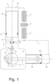
- Fig. 1 shows an example of the structure of a gamma-type Stirling engine.
- the mode of operation of such a gamma-type Stirling engine is based on the fact that, for example, a displacer piston VK in a displacer cylinder VZ, which is actuated via a crank mechanism (e.g.
- the displacer piston VK designed as a stepped piston, is at least partially hollow, and the hollow cylinder with diameter d (section S 2 of the stepped piston) enables a passage for a sufficiently long connecting rod 12, the upper end of which is inside the stepped piston VK in the area of the larger diameter D (section S 1 of the stepped piston VK) is articulated on this.
- the connecting rod 12 is therefore not connected to the lower end of the piston VK, but extends far into the piston VK into section S 1 .
- the connecting rod 12 can be made significantly longer.
- the area of the larger diameter D (section S 1 ) is clearly delimited in the exemplary embodiments shown here and lies (in the axial direction) above the step in the stepped piston at which the diameter expands from the smaller value d to the larger value D. If the transition from the smaller Diameter d to the larger diameter D does not occur in one step, but rather gradually, the area S 1 of the larger diameter is that (axial) cylinder section in which the diameter is larger than the small diameter d.
- the pivot axis of the connecting rod 12 is designated A.
- the connecting rod 12 can be articulated in the piston using different types of bearings. For example, a cylindrical plain bearing or rolling bearing can be used. Alternatively, a spherical joint bearing can be used. This can be arranged, for example, at the upper end of the connecting rod 12. As mentioned, the connecting rod is articulated in the first section S 1 (in which the diameter of the piston VK is larger than the small diameter d) of the stepped piston. This means that the pivot axis A of the connecting rod 12 lies in the section S 1 .
- a guide element F both in the area of the large diameter D (section S 1 ) of the stepped piston VK and in the area of the small diameter d (section S 2 ). (sliding surfaces) must be provided. Because of the low ratio of crank radius to connecting rod length, the piston force perpendicular to the piston center axis S is relatively low. Since this force is distributed between the two guide surfaces F, an extremely low specific surface load on the sliding surfaces occurs. This arrangement allows the use of oil-free sliding elements as guide elements F, for example made of PTFE-graphite compounds with a low coefficient of friction. The two sliding elements F also ensure precise linear guidance of the piston VK and prevent tilting movements, as can occur with one-piece or closely spaced guide elements.
- the diameter of the stepped piston VK can be dimensioned, for example, in such a way that the smaller diameter d of the stepped piston (outer diameter of the hollow cylinder) has approximately 70% of the larger diameter D of the stepped piston, corresponding to an area division of the annular surface that is formed ((D 2 -d 2 ) ⁇ ⁇ /4) in relation to the circular area defined by the hollow cylinder (d 2 ⁇ /4) of around 1: 1.
- the annular volume which is filled with cooled working gas during operation is between the second section S 2 of the stepped piston VK and the cylinder surface there is an annular volume which is filled with cooled working gas during operation is.
- the area below the step of the stepped cylinder is therefore the “cool side” C the stepped piston VK or the displacement cylinder VZ.
- the cylinder volume in the displacement cylinder VZ above the stepped piston VK is filled with hot working gas during operation.
- the area above the first section S 1 of the stepped piston VK is therefore the "hot side" H.
- the hot side H and the cool side C of the displacement cylinder VZ are connected via heater E, regenerator R and cooler K, which is why there is essentially the same pressure on both sides.
- the sealing ring 21 essentially serves to prevent process gas from flowing through (leakage) between the staged piston VK and the inner cylinder wall.
- the sealing ring 20 must seal the interior of the displacement cylinder VZ against the buffer space P, which is why the sealing ring 20 will generally be designed as a piston ring.
- the seal 22 arranged on the working piston AK must seal the working space of the working cylinder AZ against a buffer space P underneath, which is why the seal 22 will usually also be designed as a piston ring.
- piston guides F and piston seals 20, 21 are mounted on or in the piston as elements that move with the piston or are arranged on the inside of the cylinder as fixed, non-moving elements and slide along the piston skirt.
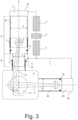
- Exemplary Fig. 3 the piston ring 21 and the guide element F are arranged in the area of the large diameter D of the stepped piston and the elements slide accordingly on the inner wall of the cylinder VZ.
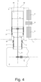
- the guide element F and the piston ring 20 are fixedly attached to the inside of the cylinder.
- the working pistons AK in the present example can be constructed essentially in the same way as the displacer piston VK, which is designed as a stepped piston, in the previous example Fig. 3 , and reference is made to the associated description above. How the two types of engines work Fig. 3 and 4 However, it is different (see description above). Fig. 1 and 2 ).
- the working pistons AK designed as stepped pistons can differ from the displacer piston VK designed as stepped pistons from the previous example, for example in the seals.
- the sealing rings 20 and 21 can both be designed as (pressure-loaded) piston rings, since they have to withstand the pressure difference between the hot side H (expansion space) and the cool side C (compression space) of the working cylinders AZ, AZ '.
- oil scraper elements A oil scraper rings
- section S 2 small piston diameter
- a low lambda value r K / l P
- r K / l P enables an approximately sinusoidal piston movement accompanied by low second-order inertial forces and a favorable course of the gas mass flow through heater E, regenerator R and cooler K.
- the working piston AK is approximately in the middle position, which is why no offset is visible on the crankshaft 10.
- Fig. 5 shows another embodiment of a gamma-type Stirling engine, which is constructed similarly and to the example Fig. 3 .
- the working piston AK is designed as a single-acting stepped piston.
- the stepped piston has a first section Si ⁇ with a larger outside diameter D' and a second section S 2 ' with a smaller outside diameter d'.
- the working space AR of the working cylinder AZ is the annular space that is formed between the cylinder inner wall and the second section S 2 ' of the stepped piston.
- the connecting line L between the cool side C of the displacement cylinder VZ and the working cylinder consequently opens into the annular space mentioned (cylinder space AR).
- Fig. 6 shows a further exemplary embodiment of a gamma-type Stirling engine, which - as far as the function and design of the pistons are concerned - is similar to the previous example Fig. 5 is very similar.
- the main difference between the examples Fig. 5 and 6 consists in the position of the cylinders relative to each other.
- the longitudinal axes S and S' of the displacement cylinder VZ and working cylinder AZ are parallel, whereas in the previous example the longitudinal axes S and S' are essentially parallel enclose a right angle and thus form a V-engine.
- the working piston AK is designed as an annular piston (ring piston) and moves coaxially to the displacer piston VK.
- the outer diameter of the annular piston AK is designated D A and the inner diameter of the annular piston corresponds (apart from the piston clearance) to the small diameter d of the stepped piston VK.
- the section S 2 of the stepped piston VK with the smaller diameter d is passed through the annular piston AK.
- the sealing rings can be arranged on the annular piston AK, once sealing on the outside (seal 22a) and once sealing on the inside (seal 22b).
- the guide-sliding surfaces F can be arranged on the annular piston AK (inside and outside).
- other designs are also possible in this regard, for example the arrangement of the piston ring 22b on the stepped piston VK in section S 2 or the arrangement of the guide-sliding surfaces F on the cylinder Z.
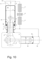
- the connecting rod 12 is passed through the tube R and is articulated inside the differential piston VK. This means that the same favorable ratio of crank radius r K to connecting rod length l p (lambda value, see Fig. 1 ) can be achieved as in the example Fig. 3 . For the rest, see the explanations Fig. 3 referred.
- the example from Fig. 11 is a modification of the example Fig. 5 . Both examples are functionally and kinematically equivalent.
- the displacement cylinder VZ and displacement piston VK are constructed in the same way as in the previous example Fig. 10 . This design replaces the stepped piston Fig. 5 .
- the working piston AK is according to Fig. 11 designed as an annular piston, which is also arranged between a tube R', which projects into the working piston AK, and is sealed towards the lateral surface of a tube R' (see, for example, piston ring 23).
- the tube R' is - analogous to the tube R in the displacement cylinder VZ - rigidly connected to the motor housing and, as mentioned, protrudes into the working cylinder AZ.
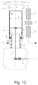
- the example from Fig. 12 is a modification of the example Fig. 4 , whereby the stepped piston from Fig. 4 was replaced by a differential piston.
- Working cylinder AZ and working piston AK are essentially constructed in the same way as displacement piston VK and displacement cylinder in Fig. 11 and reference is made to the explanations above.
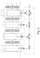
- Fig. 4 can be done analogously to the example Fig. 2 several (e.g. four) cylinder units can be connected to form a double-acting Alpha-type Stirling engine.
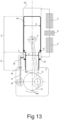
- Fig. 13 shows an example of a hot gas engine that has become known as the Manson engine. Since the working gas does not circulate in a closed circuit (but is connected to the buffer space or the atmosphere via a valve), the Manson engine shown is not, strictly speaking, a Stirling engine.
- the Stepped piston functions equally as a displacer and working piston and is designated AK in the present example.
- a valve V is opened for a short time, which connects the annular cylinder space (between the narrower section of the stepped piston and the inner wall of the cylinder AZ) with the ambient pressure in the buffer space P.
- the gearbox (cf. Fig. 14 , gear room G) is not used as a buffer room, but works under atmospheric pressure.
- the buffer space (which is under the pressure of the working gas) must be sealed against the gearbox space, which is done with a piston rod, for example using special sealing elements.
- a sealing element is known per se.
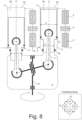
- Fig. 14 shows a piston-cylinder unit of a double-acting Stirling engine of the Alpha type.
- piston-cylinder units e.g. four as in the example Fig. 2
- a double-acting stepped piston is provided as the working piston AK according to the example shown.
- the stepped piston AK has a first section S 1 with a larger diameter D and a second section S 2 with a smaller diameter d, with the stepped piston AK at least partially (at least in the area of the second section S 2 with a diameter d ) is hollow.
- the stepped piston AK is not directly connected to a connecting rod of a crank drive, but points (as in the example).
- Fig. 2 a piston rod 13.
- the guide and sealing elements of the piston rod 13 can be arranged within the piston shaft of the stepped piston (section S 2 with outside diameter d) facing the crank mechanism.
- the piston rod 13 can be connected to a crankshaft, for example via a connecting rod, in the same or similar manner as in the example Fig. 2 (with the associated disadvantages).
- crank drive e.g. crankshaft 10, cf. e.g Fig. 2
- a partition 33 separates the crankcase between the buffer space P and the transmission space G, in which the transmission is arranged (in Fig. 14 not shown, cf. Fig. 7 and 8th ).
- the piston rod 13 connected to the stepped piston AK is passed through an opening in the partition 33.
- the seal comprises a sleeve 31 which is rigidly connected to the partition 33 and through which the piston rod 13 runs.
- An annular sealing element 35 is arranged around the piston rod 13 within the sleeve 31.
- the sealing element 35 is clamped between two conically shaped disks 34 along the longitudinal axis S of the piston rod 13 (cylinder axis S).
- the preload force required for this is generated by a spring 32, which can be arranged inside the sleeve 31 around the piston rod 13 (for example in the case of a spiral spring) and which exerts a force on the disks 34 along the longitudinal axis S of the piston rod 13.
- a spring 32 which can be arranged inside the sleeve 31 around the piston rod 13 (for example in the case of a spiral spring) and which exerts a force on the disks 34 along the longitudinal axis S of the piston rod 13.
- Fig. 2 and 4 There is no separation between buffer space P and gear space G and the crank mechanism is arranged in the buffer space.
- the present example allows a separation of buffer space P and transmission space G, so that the transmission can work under ambient pressure.
- a construction according to Fig. 2 would theoretically require no buffer space.
- a separate buffer space P can be
- Example 2 The hot gas machine according to Example 1, wherein the stepped piston (VK; AK) has sliding surfaces in both the first section (S 1 ) and the second section (S2) which slide on the cylinder surface.
- Example 3 The hot gas machine according to Example 1 or 2, wherein the cylinder (VZ; AZ; Z) has guide elements (F) which slide on the piston surface in the first section (S 1 ) and in the second section (S 2 ) of the stepped piston (VK; AK).
- Example 4 The hot gas machine according to one of Examples 1 to 3, wherein the stepped piston (VK; AK) has sealing rings (20, 21) both in the first section (S 1 ) and in the second section (S 2 ).
- Example 5 The hot gas machine according to one of Examples 1 to 4, wherein the connecting rod (12) is articulated in the stepped piston (VK; AK) by means of a plain bearing or a roller bearing or by means of a spherical joint bearing.
- Example 6 The hot gas machine according to one of Examples 1 to 5, wherein the second section (S 2 ) of the stepped piston (VK; AK) facing the transmission opens into a buffer space (P) for the working gas of the Stirling engine.
- Example 9 The hot gas machine according to one of Examples 1 to 7, wherein the Stirling engine is a beta-type Stirling engine and has an annular piston (AK) arranged in the cylinder (Z), through which the second section (S2) of the stepped piston (VK) passes.
- the Stirling engine is a beta-type Stirling engine and has an annular piston (AK) arranged in the cylinder (Z), through which the second section (S2) of the stepped piston (VK) passes.
- Example 10 The hot gas machine according to Example 9, wherein the transmission (10) has two further connecting rods (11a, 11b), which are articulated on the annular piston (AK) symmetrically to the piston longitudinal axis (S).
- Example 12 The hot gas machine according to one of Examples 1 to 7, further comprising; a further piston (AK) arranged in a further cylinder (AZ), which is coupled to the transmission by means of a further connecting rod (11).
- a further piston AK
- AZ further cylinder
- Example 13 The hot gas machine according to Example 12, whereby the staged piston is a displacer piston (VK) and the further piston is a working piston (AK), which is also designed as a staged piston or as an annular piston.
- VK displacer piston
- AK working piston
- Example 17 The hot gas machine according to Example 16, wherein the connecting rod (12) runs internally through the second section (S 2 ) of the stepped piston and is articulated in the first section (S 1 ) of the stepped piston (VK; AK).
- Example 18 The hot gas machine according to Example 15, which further comprises: a tube (R, R') which projects into the cylinder (VZ; AZ), with one end of the differential piston (VK; AK) arranged between the tube (R, R') and an inner wall of the cylinder (VZ; AZ). is.
- Example 19 The hot gas machine according to Example 18, whereby the tube (R, R') protrudes so far into the cylinder (VZ; AZ) that it also protrudes into the interior of the differential piston (VK; AK) when it is at its top dead center.
- Example 20 The hot gas machine according to Example 18 or 19, where pipe (R, R'), differential piston (VK; AK) and cylinder (VZ; AZ) are arranged coaxially to one another.
- Example 21 The hot gas machine according to one of Examples 18 to 20, where the tube (R, R') is immovable relative to the cylinder (VZ; AZ).
- Example 22 The hot gas machine according to one of Examples 18 to 21, wherein a sealing ring (20) is arranged between the tube (R, R') and an inner wall of the differential piston (VK; AK).
- Example 23 The hot gas machine according to one of Examples 15 to 22, which further comprises: a further piston (AK) arranged in a further cylinder (AZ), which is coupled to the transmission by means of a further connecting rod (11).
- a further piston AK
- AZ further cylinder
- Example 26 The hot gas machine according to Example 25, wherein the seal has a sleeve (31) in which a spring (3) is arranged, which presses on a sealing element (35) arranged between the sleeve (31) and the piston rod (13).
Landscapes
- Engineering & Computer Science (AREA)
- Chemical & Material Sciences (AREA)
- Combustion & Propulsion (AREA)
- Mechanical Engineering (AREA)
- General Engineering & Computer Science (AREA)
- Pistons, Piston Rings, And Cylinders (AREA)
- Compressors, Vaccum Pumps And Other Relevant Systems (AREA)
- Fluid-Damping Devices (AREA)
- Shafts, Cranks, Connecting Bars, And Related Bearings (AREA)
Applications Claiming Priority (3)
| Application Number | Priority Date | Filing Date | Title |
|---|---|---|---|
| DE102017109967.0A DE102017109967B9 (de) | 2017-05-09 | 2017-05-09 | Stirlingmaschine mit stufenkolben |
| PCT/EP2018/061441 WO2018206412A1 (fr) | 2017-05-09 | 2018-05-03 | Machine à gaz chaud à piston étagé |
| EP18722503.2A EP3622167B1 (fr) | 2017-05-09 | 2018-05-03 | Machine à gaz chaud à piston étagé |
Related Parent Applications (1)
| Application Number | Title | Priority Date | Filing Date |
|---|---|---|---|
| EP18722503.2A Division EP3622167B1 (fr) | 2017-05-09 | 2018-05-03 | Machine à gaz chaud à piston étagé |
Publications (2)
| Publication Number | Publication Date |
|---|---|
| EP4273393A2 true EP4273393A2 (fr) | 2023-11-08 |
| EP4273393A3 EP4273393A3 (fr) | 2024-01-10 |
Family
ID=62116448
Family Applications (2)
| Application Number | Title | Priority Date | Filing Date |
|---|---|---|---|
| EP23177758.2A Pending EP4273393A3 (fr) | 2017-05-09 | 2018-05-03 | Machine à gaz chaud à piston étagé |
| EP18722503.2A Active EP3622167B1 (fr) | 2017-05-09 | 2018-05-03 | Machine à gaz chaud à piston étagé |
Family Applications After (1)
| Application Number | Title | Priority Date | Filing Date |
|---|---|---|---|
| EP18722503.2A Active EP3622167B1 (fr) | 2017-05-09 | 2018-05-03 | Machine à gaz chaud à piston étagé |
Country Status (8)
| Country | Link |
|---|---|
| US (2) | US11215139B2 (fr) |
| EP (2) | EP4273393A3 (fr) |
| JP (1) | JP7202365B2 (fr) |
| CA (1) | CA3096716C (fr) |
| DE (1) | DE102017109967B9 (fr) |
| ES (1) | ES2951904T3 (fr) |
| PL (1) | PL3622167T3 (fr) |
| WO (1) | WO2018206412A1 (fr) |
Families Citing this family (1)
| Publication number | Priority date | Publication date | Assignee | Title |
|---|---|---|---|---|
| DE102017109967B9 (de) * | 2017-05-09 | 2020-05-07 | Frauscher Holding Gmbh | Stirlingmaschine mit stufenkolben |
Citations (9)
| Publication number | Priority date | Publication date | Assignee | Title |
|---|---|---|---|---|
| US3940934A (en) | 1971-09-20 | 1976-03-02 | Kommanditbolaget United Stirling (Sweden) Ab & Co. | Stirling engines |
| US4069671A (en) | 1976-07-02 | 1978-01-24 | Kommanditbolaget United Stirling (Sweden) Ab & Co. | Stirling engine combustion assembly |
| US4195554A (en) | 1977-04-07 | 1980-04-01 | Kommanditbolaget United Stirling (Sweden) Ab & Co. | Multi-cylinder double-acting hot gas engine |
| GB2174457A (en) | 1985-04-25 | 1986-11-05 | Sanden Corp | Stirling cycle engine |
| DE19904269A1 (de) | 1999-02-03 | 2000-11-09 | Michael Ruppel | Heißluftmotor |
| DE10229442A1 (de) | 2002-07-01 | 2004-01-15 | Epas Gmbh | Wärmetauscher zur Abkühlung des Arbeitsgases eines Stirlingmotors |
| WO2009082997A2 (fr) | 2007-12-28 | 2009-07-09 | Lutz Pasemann | Régénérateur pour circulation du gaz de travail non symétrique du cylindre dans un moteur stirling |
| WO2010093666A2 (fr) | 2009-02-11 | 2010-08-19 | Stirling Biopower, Inc. | Moteur stirling |
| GB2554458A (en) | 2016-09-29 | 2018-04-04 | Kontax Eng Ltd | Improvement to manson engine |
Family Cites Families (21)
| Publication number | Priority date | Publication date | Assignee | Title |
|---|---|---|---|---|
| DE259159C (fr) | ||||
| US2567637A (en) * | 1947-01-31 | 1951-09-11 | Hartford Nat Bank & Trust Co | Hot gas piston apparatus with flexible crank coupling |
| US3074229A (en) * | 1960-06-22 | 1963-01-22 | Philips Corp | Hot-gas reciprocating machine and system composed of a plurality of these machines |
| NL6410513A (fr) * | 1964-09-10 | 1966-03-11 | ||
| NL154814B (nl) | 1969-04-17 | 1977-10-17 | Philips Nv | Inrichting bevattende ten minste een cilinder met een daarin beweegbaar zuigervormig lichaam, waarbij de afdichting tussen het zuigervormige lichaam en de cilinderwand is gevormd door een rolmembraan. |
| GB1315889A (en) * | 1971-12-21 | 1973-05-02 | United Stirling Ab & Co | Two-cylinder hot gas engines |
| IT974757B (it) | 1971-12-30 | 1974-07-10 | Avermaete G Van | Motore |
| JPS4873602A (fr) * | 1971-12-30 | 1973-10-04 | ||
| US4044558A (en) * | 1974-08-09 | 1977-08-30 | New Process Industries, Inc. | Thermal oscillator |
| US4183219A (en) | 1977-02-25 | 1980-01-15 | Vargas Eduardo A | Self starting hot gas engine with means for changing the expansion ratio |
| US4107925A (en) * | 1977-03-14 | 1978-08-22 | Sanders Chapman Watson | Stirling engine |
| US4195482A (en) * | 1978-07-28 | 1980-04-01 | Moloney John S | Stirling cycle machine |
| DE8004988U1 (de) | 1980-02-25 | 1980-07-17 | Witzenmann Gmbh, Metallschlauch- Fabrik Pforzheim, 7530 Pforzheim | Zylinder-kolben-aggregat, insbesondere für stirling-machinen |
| US4452042A (en) * | 1982-09-30 | 1984-06-05 | Mechanical Technology Incorporated | Piston rod seal |
| US4563131A (en) * | 1984-04-30 | 1986-01-07 | Mechanical Technology Incorporated | Variable displacement blower |
| GB2243192B (en) | 1990-04-17 | 1993-12-01 | Energy For Sustainable Dev Lim | Stirling engines |
| GB9008522D0 (en) * | 1990-04-17 | 1990-06-13 | Energy For Suitable Dev Limite | Reciprocatory displacement machine |
| US5103643A (en) | 1991-03-11 | 1992-04-14 | Ross Melvin A | Transposed compression piston and cylinder |
| KR0131481Y1 (ko) * | 1995-09-04 | 1998-12-15 | 구자홍 | 스터링사이클 기기의 피스톤 지지구조 |
| US6324933B1 (en) * | 1999-10-06 | 2001-12-04 | Agere Systems Guardian Corp. | Planar movable stage mechanism |
| DE102017109967B9 (de) * | 2017-05-09 | 2020-05-07 | Frauscher Holding Gmbh | Stirlingmaschine mit stufenkolben |
-
2017
- 2017-05-09 DE DE102017109967.0A patent/DE102017109967B9/de active Active
-
2018
- 2018-05-03 JP JP2020513399A patent/JP7202365B2/ja active Active
- 2018-05-03 WO PCT/EP2018/061441 patent/WO2018206412A1/fr not_active Ceased
- 2018-05-03 CA CA3096716A patent/CA3096716C/fr active Active
- 2018-05-03 ES ES18722503T patent/ES2951904T3/es active Active
- 2018-05-03 US US16/611,414 patent/US11215139B2/en active Active
- 2018-05-03 EP EP23177758.2A patent/EP4273393A3/fr active Pending
- 2018-05-03 EP EP18722503.2A patent/EP3622167B1/fr active Active
- 2018-05-03 PL PL18722503.2T patent/PL3622167T3/pl unknown
-
2021
- 2021-12-16 US US17/553,317 patent/US11725607B2/en active Active
Patent Citations (9)
| Publication number | Priority date | Publication date | Assignee | Title |
|---|---|---|---|---|
| US3940934A (en) | 1971-09-20 | 1976-03-02 | Kommanditbolaget United Stirling (Sweden) Ab & Co. | Stirling engines |
| US4069671A (en) | 1976-07-02 | 1978-01-24 | Kommanditbolaget United Stirling (Sweden) Ab & Co. | Stirling engine combustion assembly |
| US4195554A (en) | 1977-04-07 | 1980-04-01 | Kommanditbolaget United Stirling (Sweden) Ab & Co. | Multi-cylinder double-acting hot gas engine |
| GB2174457A (en) | 1985-04-25 | 1986-11-05 | Sanden Corp | Stirling cycle engine |
| DE19904269A1 (de) | 1999-02-03 | 2000-11-09 | Michael Ruppel | Heißluftmotor |
| DE10229442A1 (de) | 2002-07-01 | 2004-01-15 | Epas Gmbh | Wärmetauscher zur Abkühlung des Arbeitsgases eines Stirlingmotors |
| WO2009082997A2 (fr) | 2007-12-28 | 2009-07-09 | Lutz Pasemann | Régénérateur pour circulation du gaz de travail non symétrique du cylindre dans un moteur stirling |
| WO2010093666A2 (fr) | 2009-02-11 | 2010-08-19 | Stirling Biopower, Inc. | Moteur stirling |
| GB2554458A (en) | 2016-09-29 | 2018-04-04 | Kontax Eng Ltd | Improvement to manson engine |
Also Published As
| Publication number | Publication date |
|---|---|
| ES2951904T3 (es) | 2023-10-25 |
| US11215139B2 (en) | 2022-01-04 |
| WO2018206412A1 (fr) | 2018-11-15 |
| US20200408168A1 (en) | 2020-12-31 |
| EP4273393A3 (fr) | 2024-01-10 |
| CA3096716A1 (fr) | 2018-11-15 |
| PL3622167T3 (pl) | 2023-08-21 |
| DE102017109967A1 (de) | 2018-11-15 |
| EP3622167C0 (fr) | 2023-06-07 |
| DE102017109967B4 (de) | 2018-11-29 |
| CA3096716C (fr) | 2023-12-19 |
| DE102017109967B9 (de) | 2020-05-07 |
| JP7202365B2 (ja) | 2023-01-11 |
| EP3622167A1 (fr) | 2020-03-18 |
| US11725607B2 (en) | 2023-08-15 |
| JP2020519813A (ja) | 2020-07-02 |
| US20220106926A1 (en) | 2022-04-07 |
| EP3622167B1 (fr) | 2023-06-07 |
Similar Documents
| Publication | Publication Date | Title |
|---|---|---|
| EP0761995B1 (fr) | Bielle | |
| DE102012020999A1 (de) | Hydraulischer Freilauf für variable Triebwerksteile | |
| AT515419B1 (de) | Pleuel für eine Verbrennungskraftmaschine | |
| DE3506061A1 (de) | Taumelscheibenverdichter mit einer vorrichtung zur einstellung der leistung | |
| DE102011018166A1 (de) | Vorrichtung zum Verändern eines Kompressionsverhältnisses einer Hubkolben-Brennkraftmaschine | |
| DE2262435C3 (de) | Heißgasmotor mit zwei Zylindern und zwei Kolben | |
| DE4019384A1 (de) | Brennkraftmaschine | |
| EP0607154B1 (fr) | Convertisseur d'energie selon le principe du moteur a air chaud | |
| EP0422338A2 (fr) | Amortisseur de vibrations à liquide | |
| DE3903546A1 (de) | Vorrichtung zur umwandlung einer drehbewegung in eine laengsbewegung und umgekehrt | |
| DE2357339A1 (de) | Kraftuebertragungsvorrichtung fuer kolbenmotoren oder -pumpen | |
| CH716089A2 (de) | Kompressoreinheit für Boil-Off-Gas aus einem LNG-Speichertank eines Schiffes und Verfahren zum Anhalten der Kompressoreinheit. | |
| EP3622167B1 (fr) | Machine à gaz chaud à piston étagé | |
| DE69112618T2 (de) | Stirling-motoren. | |
| DE102016212064A1 (de) | Vorrichtung zum Verändern eines Kompressionsverhältnisses einer Hubkolben-Brennkraftmaschine | |
| DE2107653A1 (de) | Teleskopische Kolben Zylinder Vorrichtung fur hydraulische Maschinen und Maschinenteile | |
| EP1126153A2 (fr) | Moteur Stirling | |
| DE102010060814A1 (de) | Kolbenkraftmaschine | |
| DE102009048716A1 (de) | Brennkraftmaschine | |
| DE69113035T2 (de) | Stirling-motoren. | |
| DE102006060659B3 (de) | Kolbenarbeitsmaschine | |
| CH499009A (de) | Freikolbenmaschine | |
| DE102017119463A1 (de) | Verbrennungskraftmaschine mit nichtzylindrischen Stützkolben | |
| DE112019001068B4 (de) | Ein Verfahren zur Verbesserung des effektiven thermischen Wirkungsgrads des Motors und ein mit diesem Verfahren hergestellter Leistungsübertragungsmechanismus | |
| DE102016119720B4 (de) | Kurbelschlaufen-Motor |
Legal Events
| Date | Code | Title | Description |
|---|---|---|---|
| PUAI | Public reference made under article 153(3) epc to a published international application that has entered the european phase |
Free format text: ORIGINAL CODE: 0009012 |
|
| STAA | Information on the status of an ep patent application or granted ep patent |
Free format text: STATUS: THE APPLICATION HAS BEEN PUBLISHED |
|
| AC | Divisional application: reference to earlier application |
Ref document number: 3622167 Country of ref document: EP Kind code of ref document: P |
|
| AK | Designated contracting states |
Kind code of ref document: A2 Designated state(s): AL AT BE BG CH CY CZ DE DK EE ES FI FR GB GR HR HU IE IS IT LI LT LU LV MC MK MT NL NO PL PT RO RS SE SI SK SM TR |
|
| PUAL | Search report despatched |
Free format text: ORIGINAL CODE: 0009013 |
|
| AK | Designated contracting states |
Kind code of ref document: A3 Designated state(s): AL AT BE BG CH CY CZ DE DK EE ES FI FR GB GR HR HU IE IS IT LI LT LU LV MC MK MT NL NO PL PT RO RS SE SI SK SM TR |
|
| RIC1 | Information provided on ipc code assigned before grant |
Ipc: F02G 1/053 20060101AFI20231207BHEP |
|
| STAA | Information on the status of an ep patent application or granted ep patent |
Free format text: STATUS: REQUEST FOR EXAMINATION WAS MADE |
|
| 17P | Request for examination filed |
Effective date: 20240710 |
|
| RBV | Designated contracting states (corrected) |
Designated state(s): AL AT BE BG CH CY CZ DE DK EE ES FI FR GB GR HR HU IE IS IT LI LT LU LV MC MK MT NL NO PL PT RO RS SE SI SK SM TR |