EP4273399B1 - Procédé de commande d'un compresseur d'air d'un véhicule - Google Patents
Procédé de commande d'un compresseur d'air d'un véhicule Download PDFInfo
- Publication number
- EP4273399B1 EP4273399B1 EP22172045.1A EP22172045A EP4273399B1 EP 4273399 B1 EP4273399 B1 EP 4273399B1 EP 22172045 A EP22172045 A EP 22172045A EP 4273399 B1 EP4273399 B1 EP 4273399B1
- Authority
- EP
- European Patent Office
- Prior art keywords
- compressor
- time
- liquid water
- abs
- water mass
- Prior art date
- Legal status (The legal status is an assumption and is not a legal conclusion. Google has not performed a legal analysis and makes no representation as to the accuracy of the status listed.)
- Active
Links
Images




Classifications
-
- F—MECHANICAL ENGINEERING; LIGHTING; HEATING; WEAPONS; BLASTING
- F04—POSITIVE - DISPLACEMENT MACHINES FOR LIQUIDS; PUMPS FOR LIQUIDS OR ELASTIC FLUIDS
- F04B—POSITIVE-DISPLACEMENT MACHINES FOR LIQUIDS; PUMPS
- F04B49/00—Control, e.g. of pump delivery, or pump pressure of, or safety measures for, machines, pumps, or pumping installations, not otherwise provided for, or of interest apart from, groups F04B1/00 - F04B47/00
- F04B49/02—Stopping, starting, unloading or idling control
-
- F—MECHANICAL ENGINEERING; LIGHTING; HEATING; WEAPONS; BLASTING
- F04—POSITIVE - DISPLACEMENT MACHINES FOR LIQUIDS; PUMPS FOR LIQUIDS OR ELASTIC FLUIDS
- F04B—POSITIVE-DISPLACEMENT MACHINES FOR LIQUIDS; PUMPS
- F04B35/00—Piston pumps specially adapted for elastic fluids and characterised by the driving means to their working members, or by combination with, or adaptation to, specific driving engines or motors, not otherwise provided for
- F04B35/04—Piston pumps specially adapted for elastic fluids and characterised by the driving means to their working members, or by combination with, or adaptation to, specific driving engines or motors, not otherwise provided for the means being electric
-
- F—MECHANICAL ENGINEERING; LIGHTING; HEATING; WEAPONS; BLASTING
- F04—POSITIVE - DISPLACEMENT MACHINES FOR LIQUIDS; PUMPS FOR LIQUIDS OR ELASTIC FLUIDS
- F04B—POSITIVE-DISPLACEMENT MACHINES FOR LIQUIDS; PUMPS
- F04B39/00—Component parts, details, or accessories, of pumps or pumping systems specially adapted for elastic fluids, not otherwise provided for in, or of interest apart from, groups F04B25/00 - F04B37/00
- F04B39/16—Filtration; Moisture separation
-
- F—MECHANICAL ENGINEERING; LIGHTING; HEATING; WEAPONS; BLASTING
- F04—POSITIVE - DISPLACEMENT MACHINES FOR LIQUIDS; PUMPS FOR LIQUIDS OR ELASTIC FLUIDS
- F04B—POSITIVE-DISPLACEMENT MACHINES FOR LIQUIDS; PUMPS
- F04B49/00—Control, e.g. of pump delivery, or pump pressure of, or safety measures for, machines, pumps, or pumping installations, not otherwise provided for, or of interest apart from, groups F04B1/00 - F04B47/00
- F04B49/06—Control using electricity
- F04B49/065—Control using electricity and making use of computers
-
- F—MECHANICAL ENGINEERING; LIGHTING; HEATING; WEAPONS; BLASTING
- F04—POSITIVE - DISPLACEMENT MACHINES FOR LIQUIDS; PUMPS FOR LIQUIDS OR ELASTIC FLUIDS
- F04B—POSITIVE-DISPLACEMENT MACHINES FOR LIQUIDS; PUMPS
- F04B49/00—Control, e.g. of pump delivery, or pump pressure of, or safety measures for, machines, pumps, or pumping installations, not otherwise provided for, or of interest apart from, groups F04B1/00 - F04B47/00
- F04B49/10—Other safety measures
-
- F—MECHANICAL ENGINEERING; LIGHTING; HEATING; WEAPONS; BLASTING
- F04—POSITIVE - DISPLACEMENT MACHINES FOR LIQUIDS; PUMPS FOR LIQUIDS OR ELASTIC FLUIDS
- F04B—POSITIVE-DISPLACEMENT MACHINES FOR LIQUIDS; PUMPS
- F04B2205/00—Fluid parameters
- F04B2205/09—Flow through the pump
-
- F—MECHANICAL ENGINEERING; LIGHTING; HEATING; WEAPONS; BLASTING
- F04—POSITIVE - DISPLACEMENT MACHINES FOR LIQUIDS; PUMPS FOR LIQUIDS OR ELASTIC FLUIDS
- F04B—POSITIVE-DISPLACEMENT MACHINES FOR LIQUIDS; PUMPS
- F04B2205/00—Fluid parameters
- F04B2205/11—Outlet temperature
-
- F—MECHANICAL ENGINEERING; LIGHTING; HEATING; WEAPONS; BLASTING
- F04—POSITIVE - DISPLACEMENT MACHINES FOR LIQUIDS; PUMPS FOR LIQUIDS OR ELASTIC FLUIDS
- F04B—POSITIVE-DISPLACEMENT MACHINES FOR LIQUIDS; PUMPS
- F04B2205/00—Fluid parameters
- F04B2205/50—Presence of foreign matter in the fluid
Definitions
- the present disclosure relates to a method for controlling an air compressor of a vehicle.
- Compressors are well known in vehicles and are installed for providing compressed air to various parts of the vehicles, such as to service brakes, parking brakes, air suspensions, trailers and pneumatic auxiliaries. Compressors suck atmospheric (ambient) air and increase the pressure of the air. Atmospheric air contains water vapour. The vapour contained in the atmospheric air is converted into liquid water (condensation) inside the compressor if the compressed air temperature (temperature of the air after compression) is below the so called pressure dew point ( Tdpres ), i.e. air dew point temperature after compression. When the compressed air temperature becomes strictly higher than Tdpres, liquid water (which was formed when compressed air temperature was below Tdpres ) is vaporized and can be released from the compressor as vapour in air flow.
- Tdpres pressure dew point
- Some compressors are oil lubricated. Oil is used for lubrication, sealing and dissipation of the heat due to the compression process. If the compressor duty cycle is too low, the compressor will not have time to heat and the compressed air temperature will stay below Tdpres. Vapour condenses and is converted into liquid water that stays in the compressor. Liquid water accumulation inside the compressor can lead to corrosion of internal parts and compressor failure. In case of oil lubricated compressors, the liquid accumulation may lead to oil degradation.
- a control strategy could be to run the compressor for a predetermined time period in order to increase the chances of the compressed air temperature reaching and staying above Tdpres so that accumulated liquid inside the compressor is vaporized.
- a control strategy has the disadvantage that if the predetermined time period is too short, then condensed liquid will remain inside the compressor, and if the predetermined time period is too long, then too much energy will be wasted.
- a control strategy which counteracts liquid accumulation inside the compressor in an energy efficient manner.
- US 2019/136843 A1 discloses an air compressor.
- An oil supply port supplies a lubricating oil to a compression chamber.
- An oil separator separates compressed air discharged from the compression chamber and the lubricating oil from each other.
- Oil temperature adjustment means adjusts temperature of the lubricating oil supplied to the oil supply port.
- Control means control the oil temperature adjustment means.
- Sucked-in air temperature detection means detecting temperature of the sucked-in air.
- Sucked-in air humidity detection means detecting humidity of the sucked-in air.
- the oil temperature adjustment means is controlled on the basis of detection information of the sucked-in air temperature detection means and of the sucked-in air humidity detection means.
- US 2016/245273 A1 discloses an electronic control device for a component of compressed-air generation, compressed-air processing, compressed-air storage, and/or compressed-air distribution.
- the electronic control device falls back upon one or more models, which, as component-related models, contain information relevant to the structure, or the behavior of the component.
- An object of the present disclosure is to provide a method which at least partly alleviates the drawbacks discussed above. This and other objects, which will become apparent in the following discussion, are achieved by a method as defined in the accompanying independent claim 1.
- the general concept is based on the realization that by monitoring the absolute humidity of the atmospheric (ambient) air entering the compressor as well as the absolute humidity of the compressed air exiting the compressor, it is possible to calculate a liquid water mass formed or evaporated inside the compressor, and to calculate how such formation or evaporation affects the cumulated liquid water mass inside the compressor.
- the compressor may run for a long enough time to evaporate the cumulated liquid water mass inside the compressor, and a short enough time to avoid wasting energy.
- a method of controlling an air compressor of a vehicle comprising:
- the compressor may be stopped when the zero liquid water mass has been acknowledged. In this way the compressor does not need to run longer than necessary for achieving the evaporation, while still making sure that the compressor has run long enough for the evaporation to have occurred.
- the control unit still receives such compressed air request, the compressor will not be stopped even though the cumulated liquid water mass is zero.
- the compressor will oftentimes be started after the control unit receives a compressed air request, however, as will be explained below, in certain situations the compressor may be started without the control unit receiving a compressed air request. This may be the case, for example, when the vehicle has been turned off and parked before all condensed water has been evaporated from the compressor. In such case, next time the vehicle is started, the control unit will know that there remains cumulated liquid water mass inside the compressor, and may restart the compressor in order to evaporate the cumulated liquid water mass. In other instance, the case may be that the ambient temperature is at such level that the Tdpres cannot be reached. In such case, the control unit may turn off the compressor as soon as no compressed air request is received, and when temperature conditions are such that Tdpres can be reached, the control unit may restart the compressor to evaporate the condensed liquid water inside the compressor.
- the method according to the present disclosure may suitably be a computer-implemented method.
- the implementation may be embodied in a control unit, such as the above-discussed control unit.
- the control unit may include a microprocessor, microcontroller, programmable digital signal processor or another programmable device.
- the control unit may also, or instead, include an application specific integrated circuit, a programmable gate array or programmable array logic, a programmable logic device, or a digital signal processor. Where it includes a programmable device such as the microprocessor, microcontroller or programmable digital signal processor mentioned above, the processor may further include computer executable code that controls operation of the programmable device.
- said formation or evaporation of liquid water mass is calculated for a series of consecutive periods of time, wherein the start of a next period of time in said series coincides with the end of the previous period of time in said series, wherein the cumulated liquid water mass inside the compressor is calculated by summarizing the calculation for said series of consecutive periods of time.
- the method comprises storing the most recently calculated value of the cumulated liquid water mass in an electronic memory.
- an electronic memory may suitably be accessible by the control unit, either in the form of an internal memory in the control unit or an external memory with which the control unit can communicate by wire or wirelessly.
- the method comprises, when the vehicle is turned on after having been turned off:
- the calculations and updating may continue when the vehicle is turned on again and the compressor is restarted.
- the method comprises, when the compressor has been stopped before the cumulated liquid water mass has returned to zero:
- This exemplary embodiment reflects a situation in which the control unit may determine that the compressor will, under the present conditions, not be able to evaporate the condensed liquid water inside the compressor, and therefore stops the compressor when there is no compressed air request from other parts of the vehicle.
- the control unit may once again start the compressor and calculate the change in cumulated liquid water mass in accordance with the above described control strategy.
- this mass is liquid water mass vaporized into vapour.
- the calculations may suitably be made by the control unit.
- the calculations may suitably be made by the control unit.
- the step of determining the flow rate comprises measuring the compressor speed and determining the flow rate based on the measured compressor speed. This is a convenient way to determine the flow rate as the compressor speed is generally easily acquired and known from the compressor itself (a compressor ECU may generally be sending its actual speed via a CAN bus).
- said step of determining the value H abs,atm of the absolute humidity for the atmospheric air entering the compressor comprises:
- the determination of the value H abs,atm may suitably also be based on the atmospheric pressure.
- the relative humidity may instead be estimated.
- the relative humidity may simply be determined to be 100%, thereby applying a worst case scenario for determining the absolute humidity for the atmospheric air.
- said steps of determining the value H abs,atm further comprises:
- said step of determining the value H abs,comp of the absolute humidity for the compressed air exiting the compressor comprises
- the second temperature sensor is placed in the coldest area of the compressor. This is advantageous since the coldest area presents the highest risk of condensation. However, if it is not practically possibly to place the second temperature sensor in the coldest area of the compressor, for example because of limitations due to the design of the compressor, a delta temperature ⁇ T may be taken between the measured temperature with the second sensor and the temperature used for calculation so that the coldest area is covered in the calculations.
- T ca / culation T measured - ⁇ T.
- the selected value of ⁇ T depends on the actual location of the second temperature sensor and should be defined to cover the coldest area of the compressor.
- the method comprises:
- the above exemplified embodiment not only allows the compressor to stop in time, i.e. not running the compressor when no longer needed for evaporating the condense liquid water, but also finds a balance for the actual evaporation process so that the temperature increase is at an energy efficient pace.
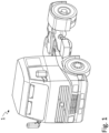
- Fig. 1 illustrates a vehicle 1 according to at least one exemplary embodiment, for which the method of the present disclosure may be implemented.
- the vehicle 1 is a heavy-duty vehicle in the form of a tractor unit.
- teachings of the present disclosure may also be implemented in other types of vehicles which use an air compressor for providing compressed air to various other parts of the vehicle.
- Fig. 2 illustrates schematically an example of components that may be used for carrying out the method of the present disclosure.
- An air compressor 2 is provided for sucking ambient air 4 and to increase the pressure of the air.
- Compressed air 6 leaves the compressor 2 and may be provided to other parts of the vehicle, such as to a service brake, a parking brake, air suspensions, a connected trailer, auxiliaries, etc.
- the compressor 2 may be operated in response to control signals 8 from a control unit 10.
- the control unit 10 controls the operation of the compressor 2.
- the control unit 10 can turn the compressor 2 on and off.
- the control unit 10 can control the rotational speed of the compressor 2.
- the control unit 10 may be used for implementing the method of this disclosure.
- the method of the present disclosure may be a computer-implemented method performed by the control unit 10.
- the control unit 10 may receive various sensor signals 12 from different sensors 14 and may process the sensor signals 12 to determine appropriate controlling of the air compressor 2.
- the control unit 10 may receive request signals 16 from various other parts or subsystems of the vehicle that demand compressed air to be provided from the compressor 2.
- a pressurized air tank 18 is illustrated as sending a request signal 16 to the control unit 10.
- the tank 18 may act as a storage for pressurized air to be distributed to other components, and when the pressure is low, a request signal 16 may be sent to the control unit 10.
- sensors 14 are illustrated, it should be understood that this is just made for explanatory purposes, and it should be understood that the specific number of sensors 14 may be varied according to the desired implementation of the method disclosed in here and its various exemplary embodiments. Examples of sensors 14 include temperature sensors, humidity sensors, pressure sensors, flow sensors, etc. Further details of the control unit 10 will be briefly discussed later in connection with Fig. 7 .
- Fig. 3 illustrates schematically a method 100 in accordance with at least one exemplary embodiment of the present disclosure. More specifically, Fig. 3 illustrates a method 100 of controlling an air compressor of a vehicle. The method 100 comprises:
- Step 1 may, for instance, be initiated by a compressed air request from another part of the vehicle.
- the compressed air request may come as a request signal 16 from a tank 18.
- Step 1 may also be initiated if the control unit knows that there is condensed liquid in the compressor, i.e. without a compressed air request having been received.
- the control unit may access an electronic memory which stored the latest calculated cumulated liquid water mass before the compressor was shut off. The fact that the compressor was shut off before all liquid had evaporated may be because the vehicle was turned off, or it may be because there was no compressed air request and that the conditions were not adequate for enabling the compressed air temperature to exceed the pressure dew point ( Tdpres ).
- Steps 2 and 3 i.e. determining the absolute humidity of the atmospheric air ( H abs,atm ) and the absolute humidity of the compressed air ( H abs,comp ) may be accomplished by using the following general method to calculate absolute humidity H abs [g/m 3 ]:
- a first temperature sensor may be used to measure the temperature of the atmospheric air, for determining/calculating the absolute humidity of the atmospheric air.
- a second temperature sensor provided inside the compressor may be used to measure a temperature of the compressed air, the for determining/calculating the absolute humidity of the compressed air.
- RH is the relative humidity of the atmospheric air. This may, for instance, be measured by means of a humidity sensor.
- the step S4 i.e. calculating by means of a control unit a liquid water mass formed or evaporated inside the compressor during a defined period of time, may be accomplished by using the below formula, which has already been discussed and explained previously in this disclosure.
- M t n H abs , atm t n ⁇ 1 + H abs , atm t n 2 ⁇ H abs , comp t n ⁇ 1 + H abs , comp t n 2 ⁇ Q t n ⁇ 1 + Q t n 2 ⁇ p
- step S5 the above determinations/calculations are repeated (step S5) and the cumulated liquid water mass is calculated in connection with each repetition (step S6).
- the cumulated liquid water mass may be calculated by using the below formula, which has already been discussed and explained previously in this disclosure.
- control unit e.g. the control unit in Fig. 2
- the control unit may stop the compressor.
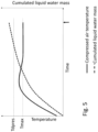
- Fig. 4 illustrates schematically a graphical representation of the implementation of at least one exemplary embodiment of the method of the present disclosure.
- the solid black line shows how the compressor air temperature increases after the compressor has been started (i.e. at time zero).
- the dotted line shows the pressure dew point temperature ( Tdpres ), which in this example is approximately 65 °C.
- Tdpres the pressure dew point temperature
- RH 100%
- the solid line representing the compressed air temperature crosses the dotted line representing Tdpres at approximately 60 s.
- the dashed line representing the cumulated liquid water mass
- the cumulated liquid water mass turns downwardly, i.e. the cumulated liquid water mass is steadily decreased as the liquid water evaporates.
- the cumulated liquid water mass has returned to zero.
- the control unit still receives a compressed air request, it can now stop the compressor.
- the liquid water has been successfully evaporated without running the compressor for longer than necessary, thereby saving energy.
- control unit may suitably calculate the pressure dew point Tdpres when starting the compressor. This may be based on ambient air temperature, relative humidity, ambient air pressure and compressed air pressure. Furthermore, the control unit may know, or may determine, the maximum temperature, Tmax, that can be reached uniformly and steadily by the air during the compression in the compressor.
- control unit may control the compressor according to the above control strategy.
- Case 1 Tmax ⁇ Tdepres
- Case 1 Actual relative humidity is known from humidity sensor or other means, (the control strategy of Case 1 can also be used if worst case 100% RH is assumed).
- the control unit may suitably limit the running time of the compressor to what is needed by the vehicle, and avoid any extra time, as Tdpres cannot be passed and condensation is occurring.
- the control unit may suitably stop the compressor when the vehicle no longer needs any more compressed air, i.e. no compress air request received. Accordingly, in this Case 1, the control unit stops the compressor even though there is liquid water, simply because not stopping the compressor would increase the accumulation of liquid water.
- the control unit may store in an electronic memory the cumulated liquid water mass that was created during this running phase when Tmax ⁇ Tdepres.
- the liquid water mass may then be eliminated the next time conditions allow to have compressed air temperature greater than the pressure dew point temperature, i.e. when conditions allow Tmax > Tdepres and evaporation can occur.
- the compressor may be restarted to evaporate liquid water either during vehicle needs or whenever the conditions (such as relative humidity, ambient temperature) are such that Tmax > Tdepres.
- Case 2 Actual relative humidity is not known, and worst case scenario is assumed, i.e. 100% RH.
- the control unit may calculates the pressure dew point for worst case 100% RH, Tdpres_100.
- control unit can calculate the RH corresponding to Tdpres_max and base the ant-condensation function on this RHmax.
- T dpres T n m log P wpres A ⁇ 1
- A, m and T n are constants for calculating the dew point temperature over different temperature ranges and are listed in commercially available lookup tables.
- the control unit may calculate and keep in memory the cumulated liquid water mass ( Tdpres_100 ; 100%RH ) as well as RHmax and the date and time that this occurs.
- the cumulated liquid water mass ( Tdpres_100 ; 100%RH ) is incremented each time Tmax ⁇ Tdpres_100, and if it reaches a defined maximum value, the control unit can warn the driver/user with a message.
- the driver/user can check actual RH and reset the cumulated liquid water mass ( Tdpres_100 ; 100%RH ) if actual RH ⁇ Hmax, or drain and exchange compressor oil if actual RH > RHmax.
- Fig. 7 schematically illustrates a control unit 10 according to at least one exemplary embodiment of the present disclosure.
- Fig. 7 illustrates, in terms of a number of functional units, the components of a control unit 10 according to exemplary embodiments of the discussions herein.
- the control unit 10 may be comprised in any vehicle disclosed herein, such as the one illustrated in Fig. 1 , and others discussed above.
- Processing circuitry 710 may be provided using any combination of one or more of a suitable central processing unit CPU, multiprocessor, microcontroller, digital signal processor DSP, etc., capable of executing software instructions stored in a computer program product, e.g. in the form of a storage medium 730.
- the processing circuitry 710 may further be provided as at least one application specific integrated circuit ASIC, or field programmable gate array FPGA.
- the processing circuitry 710 is configured to cause the control unit 10 to perform a set of operations, or steps, such as the method discussed in connection to Fig. 3 , and exemplary embodiments thereof discussed throughout this disclosure.
- the storage medium 730 may store the set of operations
- the processing circuitry 710 may be configured to retrieve the set of operations from the storage medium 730 to cause the control unit 10 to perform the set of operations.
- the set of operations may be provided as a set of executable instructions.
- the processing circuitry 710 is thereby arranged to execute exemplary methods as herein disclosed.
- the storage medium 730 may also comprise persistent storage, which, for example may be any single one or combination of magnetic memory, optical memory, solid state memory or even remotely mounted memory.
- the control unit 10 may further comprise an interface 720 for communications with at least one external device such as the compressor 2, the sensors 14 and the tank 18 discussed herein.
- the interface 720 may comprise one or more transmitters and receivers, comprising analogue and digital components and a suitable number of ports for wireline or wireless communication.
- the processing circuitry 710 controls the general operation of the control unit 10, e.g. by sending data and control signals to the interface 720 and the storage medium 730, by receiving data and reports from the interface 720, and by retrieving data and instructions form the storage medium 730.
- Other components, as well as the related functionality, of the control unit 10 are omitted in order not to obscure the concepts presented herein.
- Fig. 8 schematically illustrates a computer program product 800 according to at least one exemplary embodiment of the present disclosure. More specifically, Fig. 8 illustrates a computer readable medium 810 carrying a computer program comprising program code means 820 for performing the methods exemplified in Fig. 3 , when said program product is run on a computer.
- the computer readable medium 810 and the program code means 820 may together form the computer program product 800.
Landscapes
- Engineering & Computer Science (AREA)
- Mechanical Engineering (AREA)
- General Engineering & Computer Science (AREA)
- Computer Hardware Design (AREA)
- Control Of Positive-Displacement Pumps (AREA)
- Air-Conditioning For Vehicles (AREA)
Claims (13)
- Procédé (100) de commande d'un compresseur d'air (2) d'un véhicule (1), comprenant :- le démarrage (S1) du compresseur,- au moment du démarrage du compresseur :- la détermination (S2), pour l'air atmosphérique (4) entrant dans le compresseur, d'une valeur Habs,atm de l'humidité absolue,- la détermination (S3), pour l'air comprimé (6) sortant du compresseur, d'une valeur Habs,comp de l'humidité absolue,- sur la base des valeurs déterminées Habs,atm et Habs,comp, le calcul (S4) au moyen d'une unité de commande (10) d'une masse d'eau liquide formée ou évaporée à l'intérieur du compresseur pendant une période de temps définie,- l'exécution de manière répétée (S5) des étapes de détermination et l'étape de calcul,- pour chaque répétition, le calcul (S6) au moyen de l'unité de commande d'une masse d'eau liquide cumulée à l'intérieur du compresseur, et- l'arrêt (S7) du compresseur lorsque la masse d'eau liquide cumulée calculée est revenue à zéro et que l'unité de commande ne reçoit plus de demande d'air comprimé.
- Procédé (100) selon la revendication 1, dans lequel ladite formation ou évaporation de masse d'eau liquide est calculée pour une série de périodes de temps consécutives, dans lequel le début d'une période de temps suivante dans ladite série coïncide avec la fin de la période de temps précédente dans ladite série, dans lequel la masse d'eau liquide cumulée à l'intérieur du compresseur est calculée en sommant le calcul pour ladite série de périodes de temps consécutives.
- Procédé (100) selon l'une quelconque des revendications 1 et 2, comprenant le stockage de la valeur calculée la plus récemment de la masse d'eau liquide cumulée dans une mémoire électronique.
- Procédé (100) selon la revendication 3, comprenant, lorsque le véhicule (1) est activé après avoir été désactivé :- le redémarrage du compresseur (2),- l'exécution de manière répétée des étapes de détermination et des étapes de calcul,- pour chaque répétition, le calcul de la masse d'eau liquide cumulée à l'intérieur du compresseur et la mise à jour de la valeur stockée dans la mémoire électronique avec une nouvelle valeur calculée de la masse d'eau liquide cumulée, et- l'arrêt du compresseur lorsque la nouvelle valeur calculée de la masse d'eau liquide cumulée est zéro.
- Procédé (100) selon l'une quelconque des revendications 1 à 4, dans lequel ladite étape de calcul d'une masse d'eau liquide formée ou évaporée à l'intérieur du compresseur (2) pour une période de temps définie comprend la détermination du débit à travers le compresseur pour ladite période de temps, dans lequel la masse d'eau liquide formée ou évaporée est calculée sur la base du débit déterminé pendant la période de temps définie.
- Procédé (100) selon la revendication 5, dans lequel la masse d'eau liquide formée ou évaporée dans le compresseur pour ladite période de temps définie est calculée à l'aide de la formule :
 Mt
Mtn est la masse d'eau liquide formée ou évaporée du temps t n-1 au temps tn , où un nombre positif représente la formation et un nombre négatif représente l'évaporation,n est un nombre naturel, p est un pas de temps, nombre naturel,


 Q t
Q tn-1 est le débit à travers le compresseur déterminé au temps t n-1,Qtn est le débit à travers le compresseur déterminé au temps tn. - Procédé (100) selon la revendication 6, dans lequel la masse d'eau liquide cumulée au temps tn est calculée à l'aide de la formule :
 Mc,t
Mc,tn est la masse d'eau liquide cumulée au temps tn ,M c,tn-1 est la masse d'eau liquide cumulée au temps t n-1. - Procédé (100) selon l'une quelconque des revendications 5 à 7, dans lequel l'étape de détermination du débit comprend la mesure de la vitesse de compresseur et la détermination du débit sur la base de la vitesse de compresseur mesurée.
- Procédé (100) selon l'une quelconque des revendications 1 à 8, dans lequel ladite étape de détermination de la valeur Habs,atm de l'humidité absolue pour l'air atmosphérique entrant dans le compresseur comprend :- la mesure de l'humidité relative de l'air atmosphérique avec un capteur d'humidité (14),- la mesure de la température de l'air atmosphérique avec un premier capteur de température (14), et- la détermination de ladite valeur Habs,atm sur la base de l'humidité relative mesurée et de la température mesurée de l'air atmosphérique.
- Procédé (100) selon l'une quelconque des revendications 1 à 9, dans lequel ladite étape de détermination de la valeur Habs,comp de l'humidité absolue pour l'air comprimé sortant du compresseur comprend- la mesure de la température de l'air atmosphérique avec un premier capteur de température (14),- la détermination de la pression atmosphérique, par exemple en mesurant la pression de l'air atmosphérique avec un premier capteur de pression (14) ou en estimant la pression à partir de l'altitude de véhicule ou en estimant la pression à 1,013 bar,- la détermination de la pression de l'air comprimé, par exemple en mesurant la pression de l'air comprimé avec un second capteur de pression (14) ou un paramètre fixe dépendant de la pression de système,- la mesure de l'humidité relative de l'air atmosphérique avec un capteur d'humidité (14),- la mesure de la température de l'air comprimé avec un second capteur de température (14), et- la détermination de ladite valeur Habs,comp sur la base de la température mesurée de l'air atmosphérique, de la pression atmosphérique déterminée, de la pression déterminée de l'air comprimé, de l'humidité relative mesurée et de la température mesurée de l'air comprimé.
- Procédé (100) selon la revendication 10, dans lequel le second capteur de température est placé dans la zone la plus froide du compresseur (2).
- Procédé (100) selon l'une quelconque des revendications 1 à 11, dans lequel lesdites étapes de détermination de la valeur Habs,atm comprennent en outre :- la détermination de l'altitude actuelle du véhicule par rapport au niveau de la mer au moyen d'un système de navigation,- la détermination de la pression d'air atmosphérique sur la base de l'altitude déterminée,- la détermination de ladite valeur Habs,comp sur la base de la pression d'air atmosphérique déterminée.
- Procédé (100) selon l'une quelconque des revendications 1 à 12, comprenant :- l'utilisation d'une carte de compresseur pour sélectionner, au moyen de l'unité de commande (10), une vitesse de compresseur pour laquelle le gradient d'augmentation de température par rapport à la consommation d'énergie électrique est optimisé, et- le fonctionnement du compresseur (2) à ladite vitesse de compresseur sélectionnée.
Priority Applications (2)
| Application Number | Priority Date | Filing Date | Title |
|---|---|---|---|
| EP22172045.1A EP4273399B1 (fr) | 2022-05-06 | 2022-05-06 | Procédé de commande d'un compresseur d'air d'un véhicule |
| US18/305,417 US12359661B2 (en) | 2022-05-06 | 2023-04-24 | Method of controlling an air compressor of a vehicle |
Applications Claiming Priority (1)
| Application Number | Priority Date | Filing Date | Title |
|---|---|---|---|
| EP22172045.1A EP4273399B1 (fr) | 2022-05-06 | 2022-05-06 | Procédé de commande d'un compresseur d'air d'un véhicule |
Publications (3)
| Publication Number | Publication Date |
|---|---|
| EP4273399A1 EP4273399A1 (fr) | 2023-11-08 |
| EP4273399C0 EP4273399C0 (fr) | 2024-12-04 |
| EP4273399B1 true EP4273399B1 (fr) | 2024-12-04 |
Family
ID=81585518
Family Applications (1)
| Application Number | Title | Priority Date | Filing Date |
|---|---|---|---|
| EP22172045.1A Active EP4273399B1 (fr) | 2022-05-06 | 2022-05-06 | Procédé de commande d'un compresseur d'air d'un véhicule |
Country Status (2)
| Country | Link |
|---|---|
| US (1) | US12359661B2 (fr) |
| EP (1) | EP4273399B1 (fr) |
Families Citing this family (2)
| Publication number | Priority date | Publication date | Assignee | Title |
|---|---|---|---|---|
| US12180964B1 (en) * | 2024-04-02 | 2024-12-31 | Bendix Commercial Vehicle Systems Llc | Apparatus and method for controlling a vehicle air compressor to track water content in compressor oil |
| WO2026057259A1 (fr) * | 2024-09-13 | 2026-03-19 | Kb Intellectual Property Gmbh & Co. Kg | Procédé pour empêcher la condensation dans un compresseur et système de compresseur |
Family Cites Families (20)
| Publication number | Priority date | Publication date | Assignee | Title |
|---|---|---|---|---|
| US4431390A (en) * | 1981-10-23 | 1984-02-14 | Dresser Industries, Inc. | Condensation control apparatus for oil-flooded compressors |
| US5257008A (en) * | 1991-09-26 | 1993-10-26 | Allied-Signal Inc. | Compressed air system with warning mechanism for air dryer service life indication |
| SG104914A1 (en) * | 1997-06-30 | 2004-07-30 | Hitachi Ltd | Gas turbine |
| USRE39092E1 (en) * | 1997-06-30 | 2006-05-09 | Hitachi, Ltd. | Gas turbine with water injection |
| ITMI20022757A1 (it) * | 2002-12-23 | 2004-06-24 | Nuovo Pignone Spa | Sistema di controllo ed ottimizzazione delle emissioni |
| US7305838B2 (en) * | 2005-04-05 | 2007-12-11 | Bendix Commercial Vehicle Systems Llc | Cooling compressor intake air |
| JP2008020113A (ja) * | 2006-07-12 | 2008-01-31 | Hitachi Industrial Equipment Systems Co Ltd | 圧縮空気供給装置 |
| DE102009003396A1 (de) * | 2009-01-28 | 2010-07-29 | Continental Aktiengesellschaft | Verfahren zum Steuern der Regenerationszyklen für einen Lufttrockner in einer geschlossenen Niveauregelanlage für Fahrzeuge |
| WO2012067215A2 (fr) * | 2010-11-15 | 2012-05-24 | ナブテスコオートモーティブ株式会社 | Silencieux, soupape d'évacuation, dispositif soupape, sécheur d'air, dispositif d'alimentation en air comprimé pour un véhicule et système d'alimentation en air comprimé |
| JP5562822B2 (ja) * | 2010-12-15 | 2014-07-30 | 株式会社東芝 | ガスタービン発電設備およびその運転方法 |
| US8849604B2 (en) * | 2011-05-24 | 2014-09-30 | Clark Equipment Company | Method for calculating the probability of moisture build-up in a compressor |
| DE102013111218A1 (de) * | 2013-10-10 | 2015-04-16 | Kaeser Kompressoren Se | Elektronische Steuerungseinrichtung für eine Komponente der Drucklufterzeugung, Druckluftaufbereitung, Druckluftspeicherung und/oder Druckluftverteilung |
| JP6375874B2 (ja) * | 2014-10-31 | 2018-08-22 | 株式会社デンソー | 制御装置 |
| JP6715327B2 (ja) * | 2016-06-10 | 2020-07-01 | 株式会社日立製作所 | 空気圧縮機 |
| US10724524B2 (en) * | 2016-07-15 | 2020-07-28 | Ingersoll-Rand Industrial U.S., Inc | Compressor system and lubricant control valve to regulate temperature of a lubricant |
| KR102489912B1 (ko) * | 2016-07-25 | 2023-01-19 | 삼성전자주식회사 | 공조기기 및 그 제습량 산출 방법 |
| US10605137B2 (en) * | 2017-03-31 | 2020-03-31 | Ford Global Technologies, Llc | Methods and systems for exhaust catalyst diagnostics |
| ES2959335T3 (es) | 2018-11-19 | 2024-02-23 | Kaeser Kompressoren Se | Sensor virtual para contenido en agua en un circuito de aceite |
| KR20200070816A (ko) * | 2018-12-10 | 2020-06-18 | 현대자동차주식회사 | 응축수 발생을 방지하는 흡배기 시스템 및 그 작동 방법 |
| JP7063971B2 (ja) * | 2019-12-18 | 2022-05-09 | 三菱重工業株式会社 | 加圧空気供給システム、及び、加圧空気供給システムの起動方法 |
-
2022
- 2022-05-06 EP EP22172045.1A patent/EP4273399B1/fr active Active
-
2023
- 2023-04-24 US US18/305,417 patent/US12359661B2/en active Active
Also Published As
| Publication number | Publication date |
|---|---|
| EP4273399C0 (fr) | 2024-12-04 |
| US20230356699A1 (en) | 2023-11-09 |
| EP4273399A1 (fr) | 2023-11-08 |
| US12359661B2 (en) | 2025-07-15 |
Similar Documents
| Publication | Publication Date | Title |
|---|---|---|
| US12359661B2 (en) | Method of controlling an air compressor of a vehicle | |
| US9874384B2 (en) | Refrigeration system with superheating, sub-cooling and refrigerant charge level control | |
| US7363127B2 (en) | Air brake system monitoring for pre-trip inspection | |
| US8791803B2 (en) | Abnormality detection apparatus | |
| US9638480B1 (en) | System and method for cooling vehicle computing device | |
| US10562372B2 (en) | Systems and methods for starting-up a vehicular air-conditioning system | |
| US11536579B2 (en) | Methods and systems for determining a vehicle route based on an estimation of the weight of the vehicle | |
| JP2736511B2 (ja) | 冷却設備における冷媒充填レベルの監視方法 | |
| CN113376455A (zh) | 用于针对制动衬块磨损估计值进行emi评估的方法和系统 | |
| JPH08502343A (ja) | 空調システム内の冷却剤の量を診断する方法および装置 | |
| US6446505B1 (en) | Method for monitoring the refrigerant filling level in refrigerating system | |
| US7089815B2 (en) | Air brake system characterization by self learning algorithm | |
| CN114394101B (zh) | 轮胎与路面的附着系数的确定方法、控制装置及车辆 | |
| WO2020126646A1 (fr) | Procédé et système de surveillance d'un pneumatique en cours de fonctionnement d'un véhicule | |
| CN113071459B (zh) | 汽车制动真空泵控制方法、设备、存储介质及装置 | |
| US20260034965A1 (en) | Systems and methods for predicting windshield wiper wear | |
| ES2458555T3 (es) | Dispositivo y método para manejar un compresor de sistema de frenado neumático, en particular para vehículos industriales | |
| CN118327793A (zh) | Egr控制方法、装置、车辆及存储介质 | |
| CN107571718B (zh) | 车辆压缩机控制设备及控制方法 | |
| CN118144506A (zh) | 空调设备及用于运行空调设备的方法 | |
| JPH11235906A (ja) | タイヤ空気圧推定装置 | |
| US12515525B2 (en) | Electric air compressor control | |
| US7499790B2 (en) | Method for the plausibility check of the shut-down time of a motor vehicle with an internal combustion engine | |
| US20250172324A1 (en) | Electric vehicle heat exchanger deicing system | |
| JP6604196B2 (ja) | 車載装置 |
Legal Events
| Date | Code | Title | Description |
|---|---|---|---|
| PUAI | Public reference made under article 153(3) epc to a published international application that has entered the european phase |
Free format text: ORIGINAL CODE: 0009012 |
|
| STAA | Information on the status of an ep patent application or granted ep patent |
Free format text: STATUS: THE APPLICATION HAS BEEN PUBLISHED |
|
| AK | Designated contracting states |
Kind code of ref document: A1 Designated state(s): AL AT BE BG CH CY CZ DE DK EE ES FI FR GB GR HR HU IE IS IT LI LT LU LV MC MK MT NL NO PL PT RO RS SE SI SK SM TR |
|
| STAA | Information on the status of an ep patent application or granted ep patent |
Free format text: STATUS: REQUEST FOR EXAMINATION WAS MADE |
|
| 17P | Request for examination filed |
Effective date: 20240508 |
|
| RBV | Designated contracting states (corrected) |
Designated state(s): AL AT BE BG CH CY CZ DE DK EE ES FI FR GB GR HR HU IE IS IT LI LT LU LV MC MK MT NL NO PL PT RO RS SE SI SK SM TR |
|
| GRAP | Despatch of communication of intention to grant a patent |
Free format text: ORIGINAL CODE: EPIDOSNIGR1 |
|
| STAA | Information on the status of an ep patent application or granted ep patent |
Free format text: STATUS: GRANT OF PATENT IS INTENDED |
|
| INTG | Intention to grant announced |
Effective date: 20240701 |
|
| GRAS | Grant fee paid |
Free format text: ORIGINAL CODE: EPIDOSNIGR3 |
|
| GRAA | (expected) grant |
Free format text: ORIGINAL CODE: 0009210 |
|
| STAA | Information on the status of an ep patent application or granted ep patent |
Free format text: STATUS: THE PATENT HAS BEEN GRANTED |
|
| AK | Designated contracting states |
Kind code of ref document: B1 Designated state(s): AL AT BE BG CH CY CZ DE DK EE ES FI FR GB GR HR HU IE IS IT LI LT LU LV MC MK MT NL NO PL PT RO RS SE SI SK SM TR |
|
| REG | Reference to a national code |
Ref country code: CH Ref legal event code: EP |
|
| REG | Reference to a national code |
Ref country code: DE Ref legal event code: R096 Ref document number: 602022008305 Country of ref document: DE |
|
| REG | Reference to a national code |
Ref country code: IE Ref legal event code: FG4D |
|
| U01 | Request for unitary effect filed |
Effective date: 20241224 |
|
| U07 | Unitary effect registered |
Designated state(s): AT BE BG DE DK EE FI FR IT LT LU LV MT NL PT RO SE SI Effective date: 20250114 |
|
| PG25 | Lapsed in a contracting state [announced via postgrant information from national office to epo] |
Ref country code: HR Free format text: LAPSE BECAUSE OF FAILURE TO SUBMIT A TRANSLATION OF THE DESCRIPTION OR TO PAY THE FEE WITHIN THE PRESCRIBED TIME-LIMIT Effective date: 20241204 |
|
| PG25 | Lapsed in a contracting state [announced via postgrant information from national office to epo] |
Ref country code: ES Free format text: LAPSE BECAUSE OF FAILURE TO SUBMIT A TRANSLATION OF THE DESCRIPTION OR TO PAY THE FEE WITHIN THE PRESCRIBED TIME-LIMIT Effective date: 20241204 |
|
| PG25 | Lapsed in a contracting state [announced via postgrant information from national office to epo] |
Ref country code: NO Free format text: LAPSE BECAUSE OF FAILURE TO SUBMIT A TRANSLATION OF THE DESCRIPTION OR TO PAY THE FEE WITHIN THE PRESCRIBED TIME-LIMIT Effective date: 20250304 |
|
| PG25 | Lapsed in a contracting state [announced via postgrant information from national office to epo] |
Ref country code: GR Free format text: LAPSE BECAUSE OF FAILURE TO SUBMIT A TRANSLATION OF THE DESCRIPTION OR TO PAY THE FEE WITHIN THE PRESCRIBED TIME-LIMIT Effective date: 20250305 |
|
| PG25 | Lapsed in a contracting state [announced via postgrant information from national office to epo] |
Ref country code: RS Free format text: LAPSE BECAUSE OF FAILURE TO SUBMIT A TRANSLATION OF THE DESCRIPTION OR TO PAY THE FEE WITHIN THE PRESCRIBED TIME-LIMIT Effective date: 20250304 |
|
| U20 | Renewal fee for the european patent with unitary effect paid |
Year of fee payment: 4 Effective date: 20250526 |
|
| PG25 | Lapsed in a contracting state [announced via postgrant information from national office to epo] |
Ref country code: SM Free format text: LAPSE BECAUSE OF FAILURE TO SUBMIT A TRANSLATION OF THE DESCRIPTION OR TO PAY THE FEE WITHIN THE PRESCRIBED TIME-LIMIT Effective date: 20241204 |
|
| PG25 | Lapsed in a contracting state [announced via postgrant information from national office to epo] |
Ref country code: PL Free format text: LAPSE BECAUSE OF FAILURE TO SUBMIT A TRANSLATION OF THE DESCRIPTION OR TO PAY THE FEE WITHIN THE PRESCRIBED TIME-LIMIT Effective date: 20241204 |
|
| PG25 | Lapsed in a contracting state [announced via postgrant information from national office to epo] |
Ref country code: IS Free format text: LAPSE BECAUSE OF FAILURE TO SUBMIT A TRANSLATION OF THE DESCRIPTION OR TO PAY THE FEE WITHIN THE PRESCRIBED TIME-LIMIT Effective date: 20250404 |
|
| PG25 | Lapsed in a contracting state [announced via postgrant information from national office to epo] |
Ref country code: SK Free format text: LAPSE BECAUSE OF FAILURE TO SUBMIT A TRANSLATION OF THE DESCRIPTION OR TO PAY THE FEE WITHIN THE PRESCRIBED TIME-LIMIT Effective date: 20241204 |
|
| PG25 | Lapsed in a contracting state [announced via postgrant information from national office to epo] |
Ref country code: CZ Free format text: LAPSE BECAUSE OF FAILURE TO SUBMIT A TRANSLATION OF THE DESCRIPTION OR TO PAY THE FEE WITHIN THE PRESCRIBED TIME-LIMIT Effective date: 20241204 |
|
| PLBE | No opposition filed within time limit |
Free format text: ORIGINAL CODE: 0009261 |
|
| STAA | Information on the status of an ep patent application or granted ep patent |
Free format text: STATUS: NO OPPOSITION FILED WITHIN TIME LIMIT |
|
| REG | Reference to a national code |
Ref country code: CH Ref legal event code: L10 Free format text: ST27 STATUS EVENT CODE: U-0-0-L10-L00 (AS PROVIDED BY THE NATIONAL OFFICE) Effective date: 20251015 |
|
| 26N | No opposition filed |
Effective date: 20250905 |
|
| REG | Reference to a national code |
Ref country code: CH Ref legal event code: H13 Free format text: ST27 STATUS EVENT CODE: U-0-0-H10-H13 (AS PROVIDED BY THE NATIONAL OFFICE) Effective date: 20251223 |
|
| PG25 | Lapsed in a contracting state [announced via postgrant information from national office to epo] |
Ref country code: CH Free format text: LAPSE BECAUSE OF NON-PAYMENT OF DUE FEES Effective date: 20250531 |
|
| PG25 | Lapsed in a contracting state [announced via postgrant information from national office to epo] |
Ref country code: MC Free format text: LAPSE BECAUSE OF FAILURE TO SUBMIT A TRANSLATION OF THE DESCRIPTION OR TO PAY THE FEE WITHIN THE PRESCRIBED TIME-LIMIT Effective date: 20241204 |
|
| PG25 | Lapsed in a contracting state [announced via postgrant information from national office to epo] |
Ref country code: IE Free format text: LAPSE BECAUSE OF NON-PAYMENT OF DUE FEES Effective date: 20250506 |