EP4273438A1 - In jede richtung biegbares led-lichtband - Google Patents
In jede richtung biegbares led-lichtband Download PDFInfo
- Publication number
- EP4273438A1 EP4273438A1 EP22196297.0A EP22196297A EP4273438A1 EP 4273438 A1 EP4273438 A1 EP 4273438A1 EP 22196297 A EP22196297 A EP 22196297A EP 4273438 A1 EP4273438 A1 EP 4273438A1
- Authority
- EP
- European Patent Office
- Prior art keywords
- wires
- strip
- wire
- led light
- core
- Prior art date
- Legal status (The legal status is an assumption and is not a legal conclusion. Google has not performed a legal analysis and makes no representation as to the accuracy of the status listed.)
- Granted
Links
Images



Classifications
-
- F—MECHANICAL ENGINEERING; LIGHTING; HEATING; WEAPONS; BLASTING
- F21—LIGHTING
- F21S—NON-PORTABLE LIGHTING DEVICES; SYSTEMS THEREOF; VEHICLE LIGHTING DEVICES SPECIALLY ADAPTED FOR VEHICLE EXTERIORS
- F21S4/00—Lighting devices or systems using a string or strip of light sources
- F21S4/20—Lighting devices or systems using a string or strip of light sources with light sources held by or within elongate supports
- F21S4/22—Lighting devices or systems using a string or strip of light sources with light sources held by or within elongate supports flexible or deformable, e.g. into a curved shape
-
- F—MECHANICAL ENGINEERING; LIGHTING; HEATING; WEAPONS; BLASTING
- F21—LIGHTING
- F21S—NON-PORTABLE LIGHTING DEVICES; SYSTEMS THEREOF; VEHICLE LIGHTING DEVICES SPECIALLY ADAPTED FOR VEHICLE EXTERIORS
- F21S4/00—Lighting devices or systems using a string or strip of light sources
- F21S4/20—Lighting devices or systems using a string or strip of light sources with light sources held by or within elongate supports
- F21S4/22—Lighting devices or systems using a string or strip of light sources with light sources held by or within elongate supports flexible or deformable, e.g. into a curved shape
- F21S4/24—Lighting devices or systems using a string or strip of light sources with light sources held by or within elongate supports flexible or deformable, e.g. into a curved shape of ribbon or tape form, e.g. LED tapes
-
- F—MECHANICAL ENGINEERING; LIGHTING; HEATING; WEAPONS; BLASTING
- F21—LIGHTING
- F21V—FUNCTIONAL FEATURES OR DETAILS OF LIGHTING DEVICES OR SYSTEMS THEREOF; STRUCTURAL COMBINATIONS OF LIGHTING DEVICES WITH OTHER ARTICLES, NOT OTHERWISE PROVIDED FOR
- F21V23/00—Arrangement of electric circuit elements in or on lighting devices
- F21V23/001—Arrangement of electric circuit elements in or on lighting devices the elements being electrical wires or cables
-
- F—MECHANICAL ENGINEERING; LIGHTING; HEATING; WEAPONS; BLASTING
- F21—LIGHTING
- F21V—FUNCTIONAL FEATURES OR DETAILS OF LIGHTING DEVICES OR SYSTEMS THEREOF; STRUCTURAL COMBINATIONS OF LIGHTING DEVICES WITH OTHER ARTICLES, NOT OTHERWISE PROVIDED FOR
- F21V23/00—Arrangement of electric circuit elements in or on lighting devices
- F21V23/001—Arrangement of electric circuit elements in or on lighting devices the elements being electrical wires or cables
- F21V23/002—Arrangements of cables or conductors inside a lighting device, e.g. means for guiding along parts of the housing or in a pivoting arm
-
- F—MECHANICAL ENGINEERING; LIGHTING; HEATING; WEAPONS; BLASTING
- F21—LIGHTING
- F21Y—INDEXING SCHEME ASSOCIATED WITH SUBCLASSES F21K, F21L, F21S and F21V, RELATING TO THE FORM OR THE KIND OF THE LIGHT SOURCES OR OF THE COLOUR OF THE LIGHT EMITTED
- F21Y2103/00—Elongate light sources, e.g. fluorescent tubes
- F21Y2103/10—Elongate light sources, e.g. fluorescent tubes comprising a linear array of point-like light-generating elements
-
- F—MECHANICAL ENGINEERING; LIGHTING; HEATING; WEAPONS; BLASTING
- F21—LIGHTING
- F21Y—INDEXING SCHEME ASSOCIATED WITH SUBCLASSES F21K, F21L, F21S and F21V, RELATING TO THE FORM OR THE KIND OF THE LIGHT SOURCES OR OF THE COLOUR OF THE LIGHT EMITTED
- F21Y2115/00—Light-generating elements of semiconductor light sources
- F21Y2115/10—Light-emitting diodes [LED]
Definitions
- Embodiments of the present disclosure relate to LED lighting field, and more particularly to an LED light strip bendable in any direction.
- Figs. 1 to 4 show an existing flexible light strip.
- Fig. 1 shows a strip core 1' made of soft elastic plastic or silicone. At least two main wires 20' and 21' of the same length as the light strip are preset in the strip core 1'. The two main wires are on the same horizontal line and parallel to the surface of the light strip, and a strip core groove 8' in the middle with the same length as the strip core is reserved.
- Fig. 2 shows a light string 3' which includes light sources 5', electronic components 6' and connecting wires 7'. The light string 3' will be embedded in the strip core groove 8' shown in Fig.
- a light strip is composed of multiple light string units.
- a layer of soft elastic plastic or silicone 4' encapsulates to form a complete light strip as shown in Fig. 4 .
- the existing light strip can only be top bent (as shown in Fig. 5 ). At this time, the bending force of the two main wires is equal. If it is side bent, one of the main wires 20' will be compressed, and the other main wire 21' will be elongated. Although the elastic plastic or silicone can be stretched or compressed, the light strip itself cannot meet the shortening and elongating force of the two main wires, when the bending force is large enough, the main wires will be at risk of being broken. Meanwhile, in the prior art, the light string is generally arranged on a long PCB, when the flexible light strip is bent, especially when the bending direction is not in the direction of the wide surface of the long PCB, the long PCB also has the risk of broken.
- the technical problem to be solved by the present invention is to provide an LED light strip bendable in any direction, so that the multi-direction and multi-angle bending of the light strip can be realized, and the light strip can be used in any direction, and the wire inside the light strip has high strength which is not easy to be damaged.
- an LED light strip bendable in any direction comprises:
- each said stretchable main wire includes at least two cross-combined conductive stranded wire bundles, or each said stretchable main wire includes an inner core and at least two conductive stranded wire bundles wound outside said inner core in a cross-combination; said inner core is a straight metal wire inner core, or a straight non-metallic inner core, or a wavy non-metallic inner core, or an inner core formed by winding a plurality of metal conductive wires, or an inner core formed by winding multiple metallic conductive wires and non-metallic wires.
- each said conductive stranded wire bundle includes a plurality of metal conductive wires arranged side by side, or
- a plurality of PCBs are arranged at intervals in said strip core, each said PCB is soldered with an SMD LED and/or SMD electronic components, and all said SMD LEDs and/or SMD electronic components are electrically connected; each said PCB is connected in series between two said stretchable main wires through connecting wires separately; or a plurality of said PCBs are connected in series with each other by using said connecting wires, and then are connected in series between the two stretchable main wires through said connecting wires which are bent metal wires.
- each LED light string is arranged in said strip core, and each LED light string includes a plurality of LEDs connected in series through said connecting wires, and both ends of each said LED light string are connected between two said stretchable main wires through said connecting wires which are bent metal wires.
- a plurality of FPCBs are arranged at intervals in said strip core, each said FPCB is soldered with an SMD LED and/or SMD electronic components, and all said SMD LEDs and/or SMD electronic components are electrically connected; both ends of each said LED light string are connected between two said stretchable main wires through said connecting wires which are bent metal wires.
- At least part of said connecting wires is a wavy curve connecting wire or a coil spring connecting wire.
- said connecting wires and metal conductive wires are made of iron, copper, aluminum, copper or alloys of the above-mentioned materials; and said strip core, said insulating wrapping layer, said straight non-metallic inner core, said wavy non-metallic inner core and said non-metallic wire are all made of soft plastic or silicon; and the cross-section of said stretchable main wire is circular, oval, square or asymmetrical.
- said strip core and said insulating wrapping layer are added with colored pigments.
- a stretchable main wire is embedded on both sides of the strip core respectively, and the stretchable main wire includes at least two cross-combined conductive stranded wire bundles.
- the connecting wire between the PCB, light string or FPCB where the LED is located and the main wire is in the form of a curve. Since both the main wires and the connecting wires have properties of being compressible or elongated, stretchable and bendable, the bending resistance of the LED light strip can be improved, so that it can be bent at multiple angles and in multiple directions. And it can reduce the problem of product failure when the PCB or FPCB is twisted or bent, and improves the application range and convenience of use of the product.
- the main wire is cross-combined by multi-strand metal conductive wires, which has characteristics of being not easy to loosen, break, fall off, etc., and the conductive stranded wire bundles in the main wires are all wavy along the length direction thereof, which can further Improve the tensile strength of the LED light strip, thereby improving the service life of the LED light strip.
- FIG. 6-10 it is the first embodiment of an LED light strip bendable in any direction according to the present invention.
- the LED light strip bendable in any direction includes: a strip core 1 which is made of soft material, and a stretchable main wire 2 embedded on each side of the strip core, and a plurality of LEDs 31 arranged at intervals along the length direction of the strip core in the middle.
- the cross-section of the strip core 1 is roughly concave, but it could be understood that it is not limited to this shape in other embodiments.
- the structure of the above-mentioned strip core groove 8 may not be adopted, and the stretchable main wire may be directly arranged on both sides of the strip core wire 1.
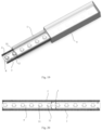
- a plurality of PCBs 3 are arranged in the strip core 1 at intervals, and each PCB is soldered with a SMD LED 31 and/or SMD electronic components, and all SMD LEDs and SMD electronic components are electrically connected.
- each PCB 3 is connected in series between the two stretchable main wires 2 through connecting wires 5 separately; or a plurality of PCBs 3 are connected in series with each other by using connecting wires 5, and then are connected in series between the two stretchable main wires 2 by using connecting wires 5.
- the connecting wires 5 are bent metal wires.
- each PCB 3 may at least include a light board body, an LED 31, electronic components and connecting wires (not shown) for connecting the LED 31 and the electronic components, wherein, the heads and tails of at least part of the PCBs 3 which are connected in series are connected between the two stretchable main wires 2 of the strip core of the LED light strip through the connecting wires 5.
- the structure of the PCB 3 and the connection between it and the stretchable main wires can be referred to Fig. 7 .
- the light strip formed by a plurality of PCBs 3 has the same length as the strip core. It could be understood that the length of the connecting wire 5 is larger than the distance between the two components it connects, thereby improving the bending performance.
- at least part of the adjacent PCBs are connected by the connecting wires, and the length of the connecting wire is larger than the distance between the adjacent PCBs;
- An insulating layer 4 encapsulates the strip core 1.
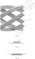
- each stretchable main wire 2 includes at least two conductive stranded wire bundles 20 combined mutually. It could be understood that the combination here can be various ways such as interweaving, intertwining and the like.
- each stretchable main wire 2 in this embodiment includes a stretchable structure.
- each stretchable main wire 2 includes at least two cross-combined conductive stranded wire bundles 20.
- each stranded conductive wire bundle 20 includes at least one metal conductive wire, and the stranded conductive wire bundles are all wavy along the length direction thereof.
- the stretchable main wire 2 when stretched or compressed by force, it can be lengthened or shortened like a spring, and it can also be automatically return to its original state without any force. Please refer to Fig.
- a schematic view of the stretchable main wire in compressed state is shown
- Fig. 10 shows a schematic view of the stretchable main wire in stretched state.
- the shape of the conductive stranded wire bundle 20 can be flat, round, square or any other shape.
- the conductive stranded wire bundle 20 has the characteristics that it is not easy to loosen, break, fall off, etc., and can be bent into any shape such as semi-arc, wave, square wave, etc.
- the cross-section of the stretchable main wire may form a circular, oval, square or asymmetrical shape.
- the conductive stranded wire bundle has obtained the characteristics of being not easy to loosen, break, fall off, etc., and its shape has an expansion and contraction function like a spring within a certain range under the action of external force, and is easy to stretch or compress.
- the strip core 1 and the insulating wrapping layer 4 can be made of soft plastic or silicone, for example, PVC, silicone, PU or other soft plastic.
- the stretchable main wire 2 can be made of copper, aluminum, steel or alloys of the above materials.
- FIG. 11 and Fig. 12 there are shown the structural schematic diagrams of another two types of stretchable main wires according to the present invention respectively.
- each stretchable main wire 2 includes an inner core 21 and at least two conductive stranded wire bundles 20 that are crossed or parallel combined and wound outside the inner core 21.
- the inner core is a straight inner core, as shown in Fig. 11 , wherein the inner core 21 may be a straight metal wire inner core, a straight non-metallic inner core, and the inner core may also be a wave-shaped inner core, as shown in Fig. 12 , the inner core 21 may be a wave-shaped non-metallic inner core.
- the inner core 21 may also be formed by winding a plurality of stranded wires, for example, by winding a plurality of metal conductive wires, or a plurality of metal conductive wires together with non-metallic wires.
- each conductive stranded wire bundle 20 includes a plurality of metal conductive wires 200 arranged side by side.
- each stranded conductive wire bundle 20 includes four metal conductive wires 200. It could be understood that the above numbers are for example only.
- the stranded conductive wire bundle 20 includes metal conductive wires 200 and non-metallic wires 201 arranged side by side and at intervals.
- Each stranded conductive wire bundle 20 in the figure includes two metal conductive wires 200 and two non-metallic wires 201, arranged alternately at intervals, and it could be understood that the above numbers are for example only.
- each metal conductive wire 200 and non-metallic wire 201 are both wavy along the length direction thereof.
- the connecting wire 5 has a curved shape, and specifically, a wavy curve connecting wire or a coil spring connecting wire can be used.
- a wavy curve connecting wire is shown. The effect offered by such arrangement is that through changing the shape of the connecting wire 5, when the light strip is bent in different directions, the light string can better adapt to the bending.
- Fig. 16 shows a structure of a coil spring connecting wire. It could be understood that, in other examples, other curved structures can also be used.
- the above-mentioned connecting wires and metal conductive wires are made of iron, copper, aluminum, copper or alloys of the above-mentioned materials.
- the strip core, the insulating wrapping layer, the straight non-metallic inner core, the wavy non-metallic inner core and the non-metallic wire are all made of soft plastic or silicon.
- the cross-section of the stretchable main wire is circular, oval, square or asymmetrical.
- the strip core and the insulating wrap layer may be transparent or foggy, and may be added color pigments, such as red, green, blue, or any other color pigments, thereby adapting the LED strip to different applications.
- the direction in which the PCB 3 is placed can be adjusted, and it can be set horizontally, vertically, or at any other position or angle, and can still achieve the same application function.
- Fig. 17 and Fig. 18 it is the second embodiment of an LED light strip bendable in any direction according to the present invention.
- each LED light string is arranged in the strip core 1, and each LED light string includes a plurality of LEDs 31 connected in series through the connecting wires 5, and each LED light string is connected in series on the two stretchable main wires 2 through the connecting wires 5 which are bent metal wires.
- the stretchable main wires 2 may adopt the structures shown in Fig. 8 and Figs. 11 to 14
- the connecting wires 5 can adopt the structure shown in Fig. 15 and Fig. 16 .
- the difference in structure from shown in Fig. 1 lies in the arrangement of the LEDs 31.
- at least one FPCB 6 is arranged in the strip core 1, and each FPCB 6 is soldered with a plurality of SMD LEDs 31 and/or SMD electronic components.
- the SMD LEDs and/or SMD electronic components are electrically connected; and each FPCB 6 is connected in series on the two stretchable main wires 2 through the connecting wires 5 which are bent metal wires.
- the stretchable main wires 2 may adopt the structures shown in Fig. 8 and Figs. 11 to 14
- the connecting wires 5 can adopt the structure shown in Fig. 15 and Fig. 16 .
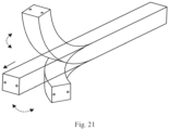
- Fig. 21 a schematic diagram of multi-directional and multi-angle bending of the present invention is shown. It can be more clearly understood that the present invention can achieve the effect of bending at multiple angles and in any directions. The figure shows the bending effects in two different directions (shown by dotted lines). It could be understood that other angles and directions of bending can also be achieved without damaging the internal circuit structure.
- the above-mentioned first to third embodiment can achieve the effect shown in Fig. 21 .
- a stretchable main wire is embedded on both sides of the strip core respectively, and the stretchable main wire includes at least two cross-combined conductive stranded wire bundles.
- the connecting wire between the PCB, light string or FPCB where the LED is located and the main wire is in the form of a curve. Since both the main wires and the connecting wires have properties of being compressible or elongated, stretchable and bendable, the bending resistance of the LED light strip can be improved, so that it can be bent at multiple angles and in multiple directions. And it can reduce the problem of product failure when the PCB or FPCB is twisted or bent, and improves the application range and convenience of use of the product.
- the main wire is cross-combined by multi-strand metal conductive wires, which has characteristics of being not easy to loosen, break, fall off, etc., and the conductive stranded wire bundles in the main wires are all wavy along the length direction thereof, which can further Improve the tensile strength of the LED light strip, thereby improving the service life of the LED light strip.
Landscapes
- Engineering & Computer Science (AREA)
- General Engineering & Computer Science (AREA)
- Led Device Packages (AREA)
- Illuminated Signs And Luminous Advertising (AREA)
- Non-Portable Lighting Devices Or Systems Thereof (AREA)
Applications Claiming Priority (1)
| Application Number | Priority Date | Filing Date | Title |
|---|---|---|---|
| CN202221059547 | 2022-05-05 |
Publications (3)
| Publication Number | Publication Date |
|---|---|
| EP4273438A1 true EP4273438A1 (de) | 2023-11-08 |
| EP4273438B1 EP4273438B1 (de) | 2024-08-07 |
| EP4273438C0 EP4273438C0 (de) | 2024-08-07 |
Family
ID=83292159
Family Applications (1)
| Application Number | Title | Priority Date | Filing Date |
|---|---|---|---|
| EP22196297.0A Active EP4273438B1 (de) | 2022-05-05 | 2022-09-19 | In jede richtung biegbares led-lichtband |
Country Status (6)
| Country | Link |
|---|---|
| US (1) | US20230358376A1 (de) |
| EP (1) | EP4273438B1 (de) |
| CN (2) | CN218237149U (de) |
| AU (1) | AU2022231777B2 (de) |
| ES (1) | ES2991332T3 (de) |
| PL (1) | PL4273438T3 (de) |
Families Citing this family (4)
| Publication number | Priority date | Publication date | Assignee | Title |
|---|---|---|---|---|
| JP2024538498A (ja) * | 2021-09-07 | 2024-10-23 | ルミレッズ リミテッド ライアビリティ カンパニー | 屈曲ワイヤを有するled照明ストリップ |
| CN218237149U (zh) * | 2022-05-05 | 2023-01-06 | 惠州市科利尔照明有限责任公司 | 一种可任意方向弯曲的led灯带 |
| CN117646876A (zh) * | 2023-11-06 | 2024-03-05 | 东莞市永锋灯饰有限公司 | 一种制造高压直插串灯的方法 |
| CN221729912U (zh) * | 2023-11-23 | 2024-09-20 | 无锡晖睿电子有限公司 | 一种具有柔性扩散灯光条的灯光伞 |
Citations (3)
| Publication number | Priority date | Publication date | Assignee | Title |
|---|---|---|---|---|
| CN112664856A (zh) * | 2021-01-05 | 2021-04-16 | 惠州市科利尔照明有限责任公司 | 一种led灯带及其led灯串结构 |
| CN112747268A (zh) * | 2021-02-03 | 2021-05-04 | 惠州市科利尔照明有限责任公司 | 一种具有高弯折性能的led灯带 |
| US20220090746A1 (en) * | 2019-11-13 | 2022-03-24 | Huizhou Clear Lighting Co., Ltd. | Led light strip bendable in multiple directions |
Family Cites Families (13)
| Publication number | Priority date | Publication date | Assignee | Title |
|---|---|---|---|---|
| US6846094B2 (en) * | 2002-08-26 | 2005-01-25 | Altman Stage Lighting, Co., Inc. | Flexible LED lighting strip |
| US9539932B2 (en) * | 2012-03-22 | 2017-01-10 | Lux Lighting Systems, Inc. | Light emitting diode lighting system |
| CN206419732U (zh) * | 2016-10-10 | 2017-08-18 | 深圳迪亚士照明科技有限公司 | 低电压led特长灯带 |
| US10663123B2 (en) * | 2017-09-07 | 2020-05-26 | Revel Gear, LLC | LED lighting system and methods |
| WO2020016076A1 (en) * | 2018-07-18 | 2020-01-23 | Lumileds Holding B.V. | Flexible light-emitting diode lighting strip with interposer |
| US10845013B2 (en) * | 2018-10-03 | 2020-11-24 | Vista Manufacturing Inc | Flexible light assembly |
| US20200300427A1 (en) * | 2019-03-21 | 2020-09-24 | Shenzhen Quncheng Optoelectronics Technology Co., Ltd | Led flexible light strip and preparation method thereof |
| EP3994959A1 (de) * | 2019-07-04 | 2022-05-11 | Lumileds Holding B.V. | Beleuchtungsvorrichtung |
| CN211146159U (zh) * | 2019-11-13 | 2020-07-31 | 惠州市科利尔照明有限责任公司 | 一种可多方向弯曲的led灯带 |
| CN212986850U (zh) * | 2020-07-01 | 2021-04-16 | 深圳市科利尔照明有限责任公司 | 一种可多方向弯曲的led灯带及其led灯串结构 |
| CN111810860A (zh) * | 2020-07-01 | 2020-10-23 | 深圳市科利尔照明有限责任公司 | 一种可多方向弯曲的led灯带及其led灯串结构 |
| CN214275423U (zh) * | 2021-02-22 | 2021-09-24 | 惠州市科利尔照明有限责任公司 | 一种柔性led灯带 |
| CN218237149U (zh) * | 2022-05-05 | 2023-01-06 | 惠州市科利尔照明有限责任公司 | 一种可任意方向弯曲的led灯带 |
-
2022
- 2022-06-21 CN CN202221559298.6U patent/CN218237149U/zh active Active
- 2022-06-21 CN CN202210700854.5A patent/CN115095811A/zh active Pending
- 2022-09-16 AU AU2022231777A patent/AU2022231777B2/en active Active
- 2022-09-18 US US17/947,162 patent/US20230358376A1/en not_active Abandoned
- 2022-09-19 EP EP22196297.0A patent/EP4273438B1/de active Active
- 2022-09-19 PL PL22196297.0T patent/PL4273438T3/pl unknown
- 2022-09-19 ES ES22196297T patent/ES2991332T3/es active Active
Patent Citations (3)
| Publication number | Priority date | Publication date | Assignee | Title |
|---|---|---|---|---|
| US20220090746A1 (en) * | 2019-11-13 | 2022-03-24 | Huizhou Clear Lighting Co., Ltd. | Led light strip bendable in multiple directions |
| CN112664856A (zh) * | 2021-01-05 | 2021-04-16 | 惠州市科利尔照明有限责任公司 | 一种led灯带及其led灯串结构 |
| CN112747268A (zh) * | 2021-02-03 | 2021-05-04 | 惠州市科利尔照明有限责任公司 | 一种具有高弯折性能的led灯带 |
Also Published As
| Publication number | Publication date |
|---|---|
| AU2022231777B2 (en) | 2023-12-14 |
| ES2991332T3 (es) | 2024-12-03 |
| EP4273438B1 (de) | 2024-08-07 |
| CN218237149U (zh) | 2023-01-06 |
| AU2022231777A1 (en) | 2023-11-23 |
| US20230358376A1 (en) | 2023-11-09 |
| CN115095811A (zh) | 2022-09-23 |
| PL4273438T3 (pl) | 2025-02-10 |
| EP4273438C0 (de) | 2024-08-07 |
Similar Documents
| Publication | Publication Date | Title |
|---|---|---|
| EP4273438A1 (de) | In jede richtung biegbares led-lichtband | |
| US20220381409A1 (en) | Led lamp strip capable of being bent in multiple directions and lamp string structure therefor | |
| EP2373123A2 (de) | Verfahren und Strukturen einer miniaturisierten Anruflampe | |
| US10041637B2 (en) | Randomly bendable and shapable LED light bar | |
| US11415278B2 (en) | LED light strip bendable in multiple directions | |
| CN108386749A (zh) | 一种柔性led灯带 | |
| CN214064618U (zh) | 一种led灯带及其led灯串结构 | |
| CN214275423U (zh) | 一种柔性led灯带 | |
| CN216383737U (zh) | 一种具有弯折pcb灯板的led灯带 | |
| CN211146159U (zh) | 一种可多方向弯曲的led灯带 | |
| CN212986850U (zh) | 一种可多方向弯曲的led灯带及其led灯串结构 | |
| CN112747268A (zh) | 一种具有高弯折性能的led灯带 | |
| EP4556785A1 (de) | Flexible led-leiste mit neuartiger fpcb-struktur | |
| CN112664856A (zh) | 一种led灯带及其led灯串结构 | |
| CN216789942U (zh) | 一种led灯带 | |
| CN218671705U (zh) | 一种可任意剪切使用的柔性灯带 | |
| CN216769140U (zh) | 一种具有加强结构的led灯带 | |
| JP5531468B2 (ja) | 絶縁電線 | |
| CN216383738U (zh) | 一种可弯曲的led灯带 | |
| CN113958891A (zh) | 一种具有弯折pcb灯板的led灯带 | |
| CN206649916U (zh) | 一种铠装型聚氯乙烯绝缘护套电力电缆 | |
| CN204518209U (zh) | 高抗张模量非导电纤维绳加强的led柔性线路板 | |
| CN2702468Y (zh) | 结构改良的连接器 | |
| CN120199537A (zh) | 一种紧凑结构带状电缆 | |
| CN115714037A (zh) | 扁平并线 |
Legal Events
| Date | Code | Title | Description |
|---|---|---|---|
| PUAI | Public reference made under article 153(3) epc to a published international application that has entered the european phase |
Free format text: ORIGINAL CODE: 0009012 |
|
| STAA | Information on the status of an ep patent application or granted ep patent |
Free format text: STATUS: REQUEST FOR EXAMINATION WAS MADE |
|
| 17P | Request for examination filed |
Effective date: 20220919 |
|
| AK | Designated contracting states |
Kind code of ref document: A1 Designated state(s): AL AT BE BG CH CY CZ DE DK EE ES FI FR GB GR HR HU IE IS IT LI LT LU LV MC MK MT NL NO PL PT RO RS SE SI SK SM TR |
|
| GRAJ | Information related to disapproval of communication of intention to grant by the applicant or resumption of examination proceedings by the epo deleted |
Free format text: ORIGINAL CODE: EPIDOSDIGR1 |
|
| STAA | Information on the status of an ep patent application or granted ep patent |
Free format text: STATUS: GRANT OF PATENT IS INTENDED |
|
| GRAP | Despatch of communication of intention to grant a patent |
Free format text: ORIGINAL CODE: EPIDOSNIGR1 |
|
| RIC1 | Information provided on ipc code assigned before grant |
Ipc: F21Y 103/10 20160101ALN20240328BHEP Ipc: F21Y 115/10 20160101ALN20240328BHEP Ipc: F21V 23/00 20150101ALI20240328BHEP Ipc: F21S 4/22 20160101AFI20240328BHEP |
|
| INTG | Intention to grant announced |
Effective date: 20240422 |
|
| GRAS | Grant fee paid |
Free format text: ORIGINAL CODE: EPIDOSNIGR3 |
|
| GRAA | (expected) grant |
Free format text: ORIGINAL CODE: 0009210 |
|
| STAA | Information on the status of an ep patent application or granted ep patent |
Free format text: STATUS: THE PATENT HAS BEEN GRANTED |
|
| AK | Designated contracting states |
Kind code of ref document: B1 Designated state(s): AL AT BE BG CH CY CZ DE DK EE ES FI FR GB GR HR HU IE IS IT LI LT LU LV MC MK MT NL NO PL PT RO RS SE SI SK SM TR |
|
| REG | Reference to a national code |
Ref country code: GB Ref legal event code: FG4D |
|
| REG | Reference to a national code |
Ref country code: CH Ref legal event code: EP |
|
| REG | Reference to a national code |
Ref country code: IE Ref legal event code: FG4D |
|
| REG | Reference to a national code |
Ref country code: DE Ref legal event code: R096 Ref document number: 602022005133 Country of ref document: DE |
|
| U01 | Request for unitary effect filed |
Effective date: 20240807 |
|
| U07 | Unitary effect registered |
Designated state(s): AT BE BG DE DK EE FI FR IT LT LU LV MT NL PT RO SE SI Effective date: 20240913 |
|
| U20 | Renewal fee for the european patent with unitary effect paid |
Year of fee payment: 3 Effective date: 20241008 |
|
| REG | Reference to a national code |
Ref country code: ES Ref legal event code: FG2A Ref document number: 2991332 Country of ref document: ES Kind code of ref document: T3 Effective date: 20241203 |
|
| REG | Reference to a national code |
Ref country code: GR Ref legal event code: EP Ref document number: 20240402591 Country of ref document: GR Effective date: 20241209 |
|
| PG25 | Lapsed in a contracting state [announced via postgrant information from national office to epo] |
Ref country code: IS Free format text: LAPSE BECAUSE OF FAILURE TO SUBMIT A TRANSLATION OF THE DESCRIPTION OR TO PAY THE FEE WITHIN THE PRESCRIBED TIME-LIMIT Effective date: 20241207 |
|
| PG25 | Lapsed in a contracting state [announced via postgrant information from national office to epo] |
Ref country code: HR Free format text: LAPSE BECAUSE OF FAILURE TO SUBMIT A TRANSLATION OF THE DESCRIPTION OR TO PAY THE FEE WITHIN THE PRESCRIBED TIME-LIMIT Effective date: 20240807 |
|
| PG25 | Lapsed in a contracting state [announced via postgrant information from national office to epo] |
Ref country code: RS Free format text: LAPSE BECAUSE OF FAILURE TO SUBMIT A TRANSLATION OF THE DESCRIPTION OR TO PAY THE FEE WITHIN THE PRESCRIBED TIME-LIMIT Effective date: 20241107 |
|
| PG25 | Lapsed in a contracting state [announced via postgrant information from national office to epo] |
Ref country code: RS Free format text: LAPSE BECAUSE OF FAILURE TO SUBMIT A TRANSLATION OF THE DESCRIPTION OR TO PAY THE FEE WITHIN THE PRESCRIBED TIME-LIMIT Effective date: 20241107 Ref country code: IS Free format text: LAPSE BECAUSE OF FAILURE TO SUBMIT A TRANSLATION OF THE DESCRIPTION OR TO PAY THE FEE WITHIN THE PRESCRIBED TIME-LIMIT Effective date: 20241207 Ref country code: HR Free format text: LAPSE BECAUSE OF FAILURE TO SUBMIT A TRANSLATION OF THE DESCRIPTION OR TO PAY THE FEE WITHIN THE PRESCRIBED TIME-LIMIT Effective date: 20240807 |
|
| PG25 | Lapsed in a contracting state [announced via postgrant information from national office to epo] |
Ref country code: SM Free format text: LAPSE BECAUSE OF FAILURE TO SUBMIT A TRANSLATION OF THE DESCRIPTION OR TO PAY THE FEE WITHIN THE PRESCRIBED TIME-LIMIT Effective date: 20240807 |
|
| PG25 | Lapsed in a contracting state [announced via postgrant information from national office to epo] |
Ref country code: CZ Free format text: LAPSE BECAUSE OF FAILURE TO SUBMIT A TRANSLATION OF THE DESCRIPTION OR TO PAY THE FEE WITHIN THE PRESCRIBED TIME-LIMIT Effective date: 20240807 |
|
| PG25 | Lapsed in a contracting state [announced via postgrant information from national office to epo] |
Ref country code: SK Free format text: LAPSE BECAUSE OF FAILURE TO SUBMIT A TRANSLATION OF THE DESCRIPTION OR TO PAY THE FEE WITHIN THE PRESCRIBED TIME-LIMIT Effective date: 20240807 |
|
| PLBE | No opposition filed within time limit |
Free format text: ORIGINAL CODE: 0009261 |
|
| STAA | Information on the status of an ep patent application or granted ep patent |
Free format text: STATUS: NO OPPOSITION FILED WITHIN TIME LIMIT |
|
| PG25 | Lapsed in a contracting state [announced via postgrant information from national office to epo] |
Ref country code: MC Free format text: LAPSE BECAUSE OF FAILURE TO SUBMIT A TRANSLATION OF THE DESCRIPTION OR TO PAY THE FEE WITHIN THE PRESCRIBED TIME-LIMIT Effective date: 20240807 |
|
| 26N | No opposition filed |
Effective date: 20250508 |
|
| PG25 | Lapsed in a contracting state [announced via postgrant information from national office to epo] |
Ref country code: IE Free format text: LAPSE BECAUSE OF NON-PAYMENT OF DUE FEES Effective date: 20240919 |
|
| U20 | Renewal fee for the european patent with unitary effect paid |
Year of fee payment: 4 Effective date: 20250820 |
|
| REG | Reference to a national code |
Ref country code: CH Ref legal event code: U11 Free format text: ST27 STATUS EVENT CODE: U-0-0-U10-U11 (AS PROVIDED BY THE NATIONAL OFFICE) Effective date: 20251001 |
|
| PGFP | Annual fee paid to national office [announced via postgrant information from national office to epo] |
Ref country code: NO Payment date: 20250923 Year of fee payment: 4 Ref country code: GR Payment date: 20250922 Year of fee payment: 4 |
|
| PGFP | Annual fee paid to national office [announced via postgrant information from national office to epo] |
Ref country code: TR Payment date: 20250915 Year of fee payment: 4 Ref country code: PL Payment date: 20250911 Year of fee payment: 4 |
|
| PGFP | Annual fee paid to national office [announced via postgrant information from national office to epo] |
Ref country code: CH Payment date: 20251001 Year of fee payment: 4 |
|
| PG25 | Lapsed in a contracting state [announced via postgrant information from national office to epo] |
Ref country code: CY Free format text: LAPSE BECAUSE OF FAILURE TO SUBMIT A TRANSLATION OF THE DESCRIPTION OR TO PAY THE FEE WITHIN THE PRESCRIBED TIME-LIMIT; INVALID AB INITIO Effective date: 20220919 |
|
| PGFP | Annual fee paid to national office [announced via postgrant information from national office to epo] |
Ref country code: ES Payment date: 20251030 Year of fee payment: 4 |
|
| PG25 | Lapsed in a contracting state [announced via postgrant information from national office to epo] |
Ref country code: HU Free format text: LAPSE BECAUSE OF FAILURE TO SUBMIT A TRANSLATION OF THE DESCRIPTION OR TO PAY THE FEE WITHIN THE PRESCRIBED TIME-LIMIT; INVALID AB INITIO Effective date: 20220919 |