EP4273823B1 - Procédé et appareil de génération d'alerte audio - Google Patents
Procédé et appareil de génération d'alerte audio Download PDFInfo
- Publication number
- EP4273823B1 EP4273823B1 EP22172061.8A EP22172061A EP4273823B1 EP 4273823 B1 EP4273823 B1 EP 4273823B1 EP 22172061 A EP22172061 A EP 22172061A EP 4273823 B1 EP4273823 B1 EP 4273823B1
- Authority
- EP
- European Patent Office
- Prior art keywords
- alert signal
- alert
- processed
- output
- signal
- Prior art date
- Legal status (The legal status is an assumption and is not a legal conclusion. Google has not performed a legal analysis and makes no representation as to the accuracy of the status listed.)
- Active
Links
Images



Classifications
-
- G—PHYSICS
- G08—SIGNALLING
- G08B—SIGNALLING SYSTEMS, e.g. PERSONAL CALLING SYSTEMS; ORDER TELEGRAPHS; ALARM SYSTEMS
- G08B3/00—Audible signalling systems, e.g. audible personal calling systems
- G08B3/10—Audible signalling systems, e.g. audible personal calling systems using electric transmission; using electromagnetic transmission
-
- H—ELECTRICITY
- H04—ELECTRIC COMMUNICATION TECHNIQUE
- H04R—LOUDSPEAKERS, MICROPHONES, GRAMOPHONE PICK-UPS OR LIKE ACOUSTIC ELECTROMECHANICAL TRANSDUCERS; ELECTRIC HEARING AIDS; PUBLIC ADDRESS SYSTEMS
- H04R3/00—Circuits for transducers
-
- B—PERFORMING OPERATIONS; TRANSPORTING
- B60—VEHICLES IN GENERAL
- B60K—ARRANGEMENT OR MOUNTING OF PROPULSION UNITS OR OF TRANSMISSIONS IN VEHICLES; ARRANGEMENT OR MOUNTING OF PLURAL DIVERSE PRIME-MOVERS IN VEHICLES; AUXILIARY DRIVES FOR VEHICLES; INSTRUMENTATION OR DASHBOARDS FOR VEHICLES; ARRANGEMENTS IN CONNECTION WITH COOLING, AIR INTAKE, GAS EXHAUST OR FUEL SUPPLY OF PROPULSION UNITS IN VEHICLES
- B60K35/00—Instruments specially adapted for vehicles; Arrangement of instruments in or on vehicles
- B60K35/20—Output arrangements, i.e. from vehicle to user, associated with vehicle functions or specially adapted therefor
- B60K35/26—Output arrangements, i.e. from vehicle to user, associated with vehicle functions or specially adapted therefor using acoustic output
- B60K35/265—Voice
-
- B—PERFORMING OPERATIONS; TRANSPORTING
- B60—VEHICLES IN GENERAL
- B60K—ARRANGEMENT OR MOUNTING OF PROPULSION UNITS OR OF TRANSMISSIONS IN VEHICLES; ARRANGEMENT OR MOUNTING OF PLURAL DIVERSE PRIME-MOVERS IN VEHICLES; AUXILIARY DRIVES FOR VEHICLES; INSTRUMENTATION OR DASHBOARDS FOR VEHICLES; ARRANGEMENTS IN CONNECTION WITH COOLING, AIR INTAKE, GAS EXHAUST OR FUEL SUPPLY OF PROPULSION UNITS IN VEHICLES
- B60K35/00—Instruments specially adapted for vehicles; Arrangement of instruments in or on vehicles
- B60K35/20—Output arrangements, i.e. from vehicle to user, associated with vehicle functions or specially adapted therefor
- B60K35/28—Output arrangements, i.e. from vehicle to user, associated with vehicle functions or specially adapted therefor characterised by the type of the output information, e.g. video entertainment or vehicle dynamics information; characterised by the purpose of the output information, e.g. for attracting the attention of the driver
-
- B—PERFORMING OPERATIONS; TRANSPORTING
- B60—VEHICLES IN GENERAL
- B60K—ARRANGEMENT OR MOUNTING OF PROPULSION UNITS OR OF TRANSMISSIONS IN VEHICLES; ARRANGEMENT OR MOUNTING OF PLURAL DIVERSE PRIME-MOVERS IN VEHICLES; AUXILIARY DRIVES FOR VEHICLES; INSTRUMENTATION OR DASHBOARDS FOR VEHICLES; ARRANGEMENTS IN CONNECTION WITH COOLING, AIR INTAKE, GAS EXHAUST OR FUEL SUPPLY OF PROPULSION UNITS IN VEHICLES
- B60K35/00—Instruments specially adapted for vehicles; Arrangement of instruments in or on vehicles
- B60K35/10—Input arrangements, i.e. from user to vehicle, associated with vehicle functions or specially adapted therefor
-
- B—PERFORMING OPERATIONS; TRANSPORTING
- B60—VEHICLES IN GENERAL
- B60K—ARRANGEMENT OR MOUNTING OF PROPULSION UNITS OR OF TRANSMISSIONS IN VEHICLES; ARRANGEMENT OR MOUNTING OF PLURAL DIVERSE PRIME-MOVERS IN VEHICLES; AUXILIARY DRIVES FOR VEHICLES; INSTRUMENTATION OR DASHBOARDS FOR VEHICLES; ARRANGEMENTS IN CONNECTION WITH COOLING, AIR INTAKE, GAS EXHAUST OR FUEL SUPPLY OF PROPULSION UNITS IN VEHICLES
- B60K35/00—Instruments specially adapted for vehicles; Arrangement of instruments in or on vehicles
- B60K35/20—Output arrangements, i.e. from vehicle to user, associated with vehicle functions or specially adapted therefor
- B60K35/26—Output arrangements, i.e. from vehicle to user, associated with vehicle functions or specially adapted therefor using acoustic output
-
- H—ELECTRICITY
- H04—ELECTRIC COMMUNICATION TECHNIQUE
- H04R—LOUDSPEAKERS, MICROPHONES, GRAMOPHONE PICK-UPS OR LIKE ACOUSTIC ELECTROMECHANICAL TRANSDUCERS; ELECTRIC HEARING AIDS; PUBLIC ADDRESS SYSTEMS
- H04R2499/00—Aspects covered by H04R or H04S not otherwise provided for in their subgroups
- H04R2499/10—General applications
- H04R2499/13—Acoustic transducers and sound field adaptation in vehicles
Definitions
- This disclosure describes a system and method for audio alert generation.
- a dedicated, separate and smaller audio subsystem comprising a micro-controller for generating the alert with little or no digital signal processing, an amplifier and a loudspeaker.
- This safety-controlled dedicated audio subsystem can be positioned, e.g., under the instrumentation panel, which leads to size constraints, and consequently, the combination of a single amplifier with a single small loudspeaker is used.
- US11120642B2 describes an audio-safety alert warning system for a vehicle with self-checking mechanism.
- EP3382663A1 discloses a system for providing functional safety for in-vehicle audio alerts.
- a method of generating an audible alert by a digital audio system configured to operate in a first operating mode and a second operating mode, the method comprising: generating or receiving an alert signal; generating a processed alert signal by processing at least a segment of the alert signal; analysing the processed alert signal to define whether the digital audio system operates in the first operating mode or the second operating mod; and in the first operating mode, generating an alert output signal comprising the alert signal; and in the second operating mode, generating an alert output signal comprising the processed alert signal.
- generating the alert output signal may further comprise combining the alert signal and the processed alert signal.
- generating the alert output signal may further comprise generating a first alert signal segment and a second alert signal segment, and generating the processed alert signal comprises processing the second alert signal segment.
- the method may further comprise at least one of (i) delaying the alert signal before the analysing and combining, and (ii) delaying the alert signal and the processed alert signal before the combining.
- analysing the processed alert signal may further comprise determining a validity of the processed alert signal.
- the method may further comprise determining a validity of the processed alert signal from a comparison of the processed alert signal and the alert signal.
- the method may further comprise determining the validity of the processed alert signal from the cross-correlation of the alert signal and the processed alert signal.
- generating a processed alert signal may further comprise replacing at least one bit in a sample of the alert signal with a parity bit, and wherein determining a validity of the processed alert signal comprises checking the parity of the alert signal sample.
- the method may further comprise configuring the digital audio system in the first operating mode in response to determining that the processed alert signal is invalid, and configuring the digital audio system in the second operating mode in response to determining that the processed alert signal is valid.
- the audio system may comprise a first system partition configured to operate at least in the first operating mode and a second system partition
- the method may further comprise: generating or receiving the alert signal in the first system partition; generating the processed alert signal in the second system partition; analysing the processed alert signal in the first system partition; generating the alert output signal in the first system partition.
- digital audio system configured to operate in a first operating mode and a second operating mode
- the digital audio system comprising: an alert signal generator configured to generate an alert signal; a processor coupled to the alert signal generator and configured to generate an processed alert signal by processing at least a segment of the alert signal; an analyser coupled to the processor and the alert signal generator and configured to analyse the processed alert signal to define whether the digital audio system operates in the first operating mode or the second operating mode; and a combiner coupled to the processor, the alert signal generator and the analyser, the combiner configured in the first operating mode to output an alert output signal comprising the alert signal, and in the second operating mode to output an alert output signal comprising the processed alert signal.
- the digital audio system may comprise a first system partition and a second system partition, wherein the alert signal generator, the analyser and the combiner are located in the first system partition and the processor is located in the second system partition.
- the combiner may be further configured to combine the alert signal and the processed alert signal, and to output an alert output signal comprising the combined alert signal and processed alert signal.
- the digital audio system may comprise: a first delay module arranged between the alert signal generator output and the combiner and analyser and configured to delay the alert signal before the analysing and combining.
- the alert signal generator may comprise a first alert signal generator output coupled to the combiner and a second alert signal generator output coupled to the processor and wherein the alert signal comprises a first alert signal segment and a second alert signal segment wherein the alert signal generator is configured to output the first alert signal segment followed by the second alert signal segment on the first alert signal generator output and to output the second alert signal segment on the second alert signal generator output.
- the digital audio system may comprise: a second delay module arranged between the first delay module and the combiner; and a third delay module arranged between a processor output and the combiner.
- the analyser may be further configured to determine a validity of the processed alert signal.
- the digital audio system may be further configured to determine the validity of the processed alert signal from a cross-correlation of the alert signal and the processed alert signal.
- the processor may be further configured to generate an processed alert signal by adding a parity bit to a processed alert signal sample and to determine the validity of the processed alert signal by a parity check of the processed alert signal sample.
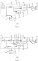
- FIG. 1 shows a method of generating an audio alert 100 by an audio system according to an embodiment.
- step 102 and alert signal is generated.
- step 104 at least part of the alert signal that is generated in step 102 is processed.
- step 106 the process alert signal is analysed to determine an operating mode.
- a first operating mode might be termed to be a safe mode or fail safe mode of operation of the audio system.
- the second operating mode might be termed to be a normal operating mode of an audio system.
- step 108 a check of the operating mode is made. If the operating mode is a safe mode (or first operating mode), then in step 112, the alert signal generated in step 102 is directly output to a loudspeaker by an amplifier. Otherwise, in step 110 the processed or enhanced alert signal is output to one or more loudspeakers via one or more amplifiers.
- Figure 2 shows a method of generating an audio alert 150 by an audio system according to an embodiment.
- an alert signal is generated.
- the alert signal is processed to generate a processed alert signal.
- the processed alert signal is compared to the alert signal. In some examples this may be done by a cross-correlation of the processed alert signal with the alert signal. However, it will be appreciated that other methods of comparison may be used.
- an operating mode is determined from the comparison. For example if the result of the comparison indicates that the processed alert signal has been somehow corrupted, then the operating mode may be considered to be in a first operating mode.
- the operating mode may be considered to be in a second operating mode.
- a weighting factor may be applied in step 160, dependent on the operating mode.
- the processed alert signal and the alert signal may be combined with the weighting factor in step 162.
- the weighting factors may be selected such that the combination of the signal may entirely or almost entirely consist of the alert signal generated in step 152, since the enhanced alert signal is considered to be corrupted, i.e. invalid.
- the weighting factors may be selected such that the combination of the signal may entirely or mostly consist of the processed alert signal generated in step 154, since the enhanced alert signal is valid.
- the method 150, 152 allows an audio system such as for example an infotainment system typically implemented in cars and other vehicles to provide audio enhanced and tuned alerts for example by including cabin equalisation, with a fallback mode to ensure the user alert is always played even if part of the system fails. This may avoid the use of for example a dedicated safety-controlled instrument cluster audio subsystem.
- FIG. 3 shows a digital audio system for generating an audio alert 200 according to an embodiment.
- the digital audio system includes an alert signal generator 202, a processor 206, a delay module 208, an analyser 216, and a combiner 220.
- the alert signal generator, the delay module 208, the analyser 216, and the combiner 220 may be located in a first system partition 210, which may also be referred to as the safe partition.
- the processor 206 may be located in a second system partition.
- An alert signal generator output 204 may be connected to an input of the processor 206 and an input of the delay module 208.
- the delay module output 214 may be connected to a first input of the combiner 220 and a first input of the analyser module 216.
- the processor output 212 may be connected to a second input of the analyser module 216 and a second input of the combiner 220.
- An analyser module output 218 may be connected to a control input of the combiner 220.
- the combiner output 222 may be connected via a digital to analog converter (not shown) to an amplifier 224.
- the amplifier output 226 may be connected to a loudspeaker 228.
- a user alert signal which may for example be a chime may be generated by the alert signal generator 202. This signal may also be referred to as a basic chime.
- the alert signal is provided to the audio processor 206, that is outside the safe partition 210.
- the audio processor 206 may apply signal enhancement.
- the processed user alert which may also be referred to as the enhanced user alert is output from the audio processor output 212 to the analyser module 216.
- the user alert signal may also be provided to the analyser module 216.
- the user alert signal is time-delayed by an amount ⁇ s by the delay module 208 which is equivalent to the expected time to process the user alert by the audio processor 206.
- the analyser module 216 may compute a consistency measure which may also be referred to as a validity measure, which is a measure that indicates whether the enhanced user alert is intact.
- One possible consistency or validity measure is the peak of the (absolute value of the) cross-correlation between the basic chime and the enhanced chime. Indeed, in the absence of processing and of an additional audio signal, the peak should be unity, and with functional processing, it should remain high, say above 0.8. In other examples, other cross-correlation measures, such as the phase-transform based cross-correlation may be used.
- the processed alert signal may be mixed with concurrent audio content by the processor 206.
- the peak value of the cross-correlation may decrease.
- the alert signal for example a chime is typically substantially louder than the concurrent audio content
- the cross-correlation is still a reliable consistency measure in the presence of concurrent audio, and should remain above a value for example 0.6 to indicate a subjectively intact enhanced chime.
- this information may replace the consistency measure, and the analysis module is not required.
- the validity of the audio processing in the non-safe partition can be evaluated using a parity check as consistency measure. If a parity bit is added to the processed alert signal in the non-safe partition at the end of the non-safe processing chain, the validity of this parity bit can be assessed in the safe partition 210. The validity of the parity bit which may be averaged across the most recent samples can then be checked in the safe partition to indicate whether the processed alert signal is valid i.e. intact.
- the parity bit may be computed on all but the least significant bit of the audio samples, and may be stored in the least significant bit of an audio sample. The parity bit may be determined for each sample, or after each block of N samples. Replacing the least significant bit every N samples may reduce the distortion in the audio.
- the parity bit may also be added to the processed alert signal when it includes other audio content. Since the parity bit is added at the end of the processing chain and hence, after the addition of the concurrent audio content, any parity error will indicate a corruption of the processed alert signal.
- bit patterns can be stored in the least-significant bit positions, e.g., a fixed alternating 0/1 bit pattern, or a code that is derived from the samples other than parity, such as a scrambled version of another bit of the samples.
- the audio system 200 may be considered to be in a first mode of operation which may be considered as a safe mode.
- a processed user alert may be considered invalid if it is corrupted to such an extent that it would no longer have the expected impact on the listener, i.e. the listener would not perceive the signal as a user alert, which may be important in a safety-critical situation.
- the audio system 200 may be considered to be in a second mode of operation which may be considered as a normal mode.
- the validity measure effectively defines the operating mode of the audio system 200.
- the validity measure is output to the combination module 220 which also receives the delayed basic user alert signal and the possibly corrupted processed user alert signal.
- the combination module 220 may either combine the two signals or select one of the two signals dependent on the validity measure, and the resulting alert output signal may be provided to the amplifier 224 and loudspeaker 228.
- the combination may be a simple selection, for example only the basic alert signal is output if the processed alert signal is invalid and only the processed alert signal is output if the processed alert signal is valid.
- the signals may be combined as a weighted sum of the alert signal and the processed alert signal.
- information may be available regarding the functionality of the non-safe partition, i.e. the part of the system not located in the safe partition 210.
- the analyser module 216 may be omitted, and the information regarding the functionality of the non-safe partition may be used as the validity measure.
- FIG. 4 shows a digital audio system for generating an audio alert 300 according to an embodiment.
- the digital audio system may include an alert signal generator 302, processor 306, a first delay module 308, a second delay module 330, a third delay module 332, an analyser 316, and a combiner 320.
- the alert signal generator, the delay module 208, the analyser 316, and the combiner 320 may be located in a first system partition 310.
- the processor 306 may be located in a second system partition.
- An alert signal generator output 304 may be connected to an input of the processor 306 and an input of the first delay module 308.
- the first delay module output 314 may be connected to an input of the second delay module 330 and a first input of the analyser module 316.
- the output 334 of the second delay module 330 may be connected to a first input of the combiner 320.
- the processor output 312 may be connected to an input of the third delay module 332 and second input of the analyser module 316.
- the output 336 of the third delay module 332 may be connected to a second input of the combiner 320.
- An output 318 of the analyser module 316 may be connected to a control input of the combiner 320.
- the combiner output 322 may be connected via a digital to analog converter (not shown) to an amplifier 324.
- the amplifier output 326 may be connected to a loudspeaker 328.
- a second delay time ⁇ L is added to the user alert signal by second delay module 330, which has already been delayed by first delay module 308 by a time ⁇ S .
- a second delay time ⁇ L is added to the processed user alert by third delay module 332. This allows for a lookahead mechanism, so that the combination module 320 can anticipate a change in consistency to reduce audible artifacts during transitions by, for example, transitioning from processed user alert to basic user alert before a corrupted segment of the delayed processed user alert reaches the combination module 320.
- s out is the output signal
- s e is the processed (enhanced) alert signal
- s b is the (basic) alert signal output
- y is a weighting factor that is related to the validity measure which may also be considered as a consistency measure, c.
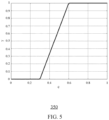
- the combiners 220, 320 may combine the user alert signal and processed user alert signal according to the graph 350 of figure 5 which shows the weighting factor or gain y on the y-axis varying between 0 and 1 and the normalized validity measure c on the x-axis varying between 0 and 1. Below a first threshold value for c, the enhanced chime is presumed corrupt, and y is zero, due to which the basic chime is output.
- the weighting factor y can also be asymmetrically temporally smoothed to reduce transition artifacts, e.g., by using a fast time constant for example between 50 milliseconds and 100 milliseconds to decrease to 0 (to play the basic alert signal), and a slower time constant, for example 0.5 seconds, to increase to 1 (to play the processed alert signal).
- the weighted combination of the basic chime, s b , and the enhanced chime, s e can be constructed in the frequency domain by taking the weighted combination of the magnitude spectrum, and the phase spectrum of the weighted combination in the time domain. This may prevent an attenuation of the signal output when the basic alert signal and the processed alert signal are not phase-aligned.
- FIG. 6 shows a digital audio system for generating an audio alert 400 according to an embodiment.
- the digital audio system may include an alert signal generator 402, processor 406, an analyser 416, and a combiner 420.
- the alert signal generator 402, the analyser 416, and the combiner 420 may be located in the first system partition 410.
- the processor 406 may be located in a second system partition.
- a first alert signal generator output 414 may be connected to an input of the combiner 420 and a first input of the analyser module 416.
- a second alert signal generator output 404 may be connected to an input of the processor 406.
- the processor output 412 may be connected to a second input of the analyser module 416 and a second input of the combiner 420.
- An analyser module output 418 may be connected to a control input of the combiner 420.
- the combiner output 422 may be connected via a digital to analog converter (not shown) to an amplifier 424.
- the amplifier output 426 may be connected to a loudspeaker 428.
- the first alert signal generator output 414 provides an alert signal which may be the same as the generator output of alert signal generators 202, 302.
- the alert signal may be considered to consist of a first (time) alert signal segment consisting of a first number of N samples followed by a second alert signal segment consisting of a second number of M samples.
- the second alert signal generator output 404 may output only the second segment of the alert signal corresponding to a lead time, which is typically set to be equal to the expected delay from the processing performed by the audio processor 306. In this way, the two signals at the input of the analyser module 416 and of the combination module 420 are synchronous. At the start of the basic chime, a first time segment equal to the lead time is skipped to obtain the second output signal of the generator module 402.
- the basic chime is played, and that after this time, the enhanced chime is played (if the non-safe partition is functional). If the lead time is sufficiently short (lower than 10ms), this will not be perceived as two separate signals.
- the audio system 400 may avoid the use of delay elements to synchronize the alert signal and processed alert signal, as done for example delay modules 208, 308, and/or to provide a look ahead function, as done for example by delay modules 330, 332.
- the audio system 400 may have a lower latency than audio system 200, 300 due to the absence of synchronisation and lookahead delays, which may be important in safety critical applications.
- the operation of audio system 400 may be further understood with reference to the graph 450 of figure 7 which shows an alert signal 456 having a first segment 452 and second segment 454. The duration of the first segment 452 may correspond to the delay through audio processor 406.
- the alert signal 456 is output on a first output and simultaneously the second segment 454 of the alert signal is output on a second output shown by waveform 458.
- Waveform 458 is processed by processor 406 and then after time t1 the processed signal is output shown by waveform 460. In this way the portion or segment of the original alert signal is time synchronized with the corresponding portion or segment of the processed alert signal before any combining.
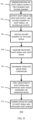
- Figure 8 shows a method of generating an audio alert 500 by an audio system according to an embodiment, for example audio system 400.
- an alert signal may be generated.
- the alert signal may have a first segment and a second segment.
- the alert signal may be output from a first output and a second segment of the alert signal may be simultaneously output on a second output.
- the second segment of the alert signal may be processed generate a processed alert signal.
- the processed alert signal may be compared to the alert signal. In some examples, this comparison may be done by a cross-correlation of the processed alert signal with the alert signal or other method.
- an operating mode may be determined from the comparison.
- Embodiments of the audio system and method may be implemented by hardware, software or a combination of hardware and software.
- the alert signal output may be a multi-channel output, and may be provided to multiple loudspeakers.
- the audio system may output a mono alert output signal played only on a single channel and loudspeaker in the safe operating mode.
- the loudspeaker used in the safe operating mode may be the closest loudspeaker to the driver, or with a fixed distribution across all loudspeakers. In the normal operating mode the processed alert signal may be processed so that it is louder for the intended user for example the vehicle driver.
- Embodiments describe a system and method that combines the safety-compliance of a separate audio system for critical user alerts, with the advanced audio processing that can be performed in the infotainment audio subsystem.
- This processing may comprise equalisation, dynamic range compression, noise-adaptive volume level, advanced mixing and 3D sound positioning.
- the audio processing involved may be performed on several separate partitions.
- One partition, the safe partition may be designed compliant to functional safety regulations, and another partition, the non-safe partition, may not necessarily be compliant to functional safety regulations.
- the basic user alert (e.g., a chime) may be generated in the safe partition.
- the basic user alert may be provided to the non-safe partition, which processes it to enhance the signal (e.g., cabin or other equalisation, dynamic range compression, noise-adaptive volume level, advanced mixing and 3D sound positioning).
- the processed alert is provided back to the safe partition.
- the processed alert is analysed to determine whether or not it has been corrupted. Indeed, if the non-safe partition has crashed, the processed alert could be all zeros, or it could contain random noise.
- the basic alert and processed alert may be combined, and sent to the output (to the amplifier and loudspeakers).
- the set of instructions/method steps described above are implemented as functional and software instructions embodied as a set of executable instructions which are effected on a computer or machine which is programmed with and controlled by said executable instructions. Such instructions are loaded for execution on a processor (such as one or more CPUs).
- processor includes microprocessors, microcontrollers, processor modules or subsystems (including one or more microprocessors or microcontrollers), or other control or computing devices.
- a processor can refer to a single component or to plural components.
- the set of instructions/methods illustrated herein and data and instructions associated therewith are stored in respective storage devices, which are implemented as one or more non-transient machine or computer-readable or computer-usable storage media or mediums.
- Such computer-readable or computer usable storage medium or media is (are) considered to be part of an article (or article of manufacture).
- An article or article of manufacture can refer to any manufactured single component or multiple components.
- the non-transient machine or computer usable media or mediums as defined herein excludes signals, but such media or mediums may be capable of receiving and processing information from signals and/or other transient mediums.
- Example embodiments of the material discussed in this specification can be implemented in whole or in part through network, computer, or data based devices and/or services. These may include cloud, internet, intranet, mobile, desktop, processor, look-up table, microcontroller, consumer equipment, infrastructure, or other enabling devices and services. As may be used herein and in the claims, the following non-exclusive definitions are provided.
- one or more instructions or steps discussed herein are automated.
- the terms automated or automatically mean controlled operation of an apparatus, system, and/or process using computers and/or mechanical/electrical devices without the necessity of human intervention, observation, effort and/or decision.
Landscapes
- Engineering & Computer Science (AREA)
- Chemical & Material Sciences (AREA)
- Combustion & Propulsion (AREA)
- Transportation (AREA)
- Mechanical Engineering (AREA)
- Physics & Mathematics (AREA)
- Acoustics & Sound (AREA)
- Signal Processing (AREA)
- Electromagnetism (AREA)
- General Physics & Mathematics (AREA)
- Circuit For Audible Band Transducer (AREA)
Claims (15)
- Procédé de génération d'une alerte audible par un système audio numérique configuré pour fonctionner dans un premier mode de fonctionnement et un second mode de fonctionnement, le procédé comportant les étapes consistant à :générer ou recevoir un signal d'alerte ;générer un signal d'alerte traité en traitant au moins un segment du signal d'alerte ;analyser le signal d'alerte traité pour définir si le système audio numérique fonctionne dans le premier mode de fonctionnement ou le second mode de fonctionnement ; etdans le premier mode de fonctionnement, générer un signal de sortie d'alerte comportant le signal d'alerte ; etdans le second mode de fonctionnement, générer un signal de sortie d'alerte comportant le signal d'alerte traité.
- Procédé selon la revendication 1, la génération du signal de sortie d'alerte comportant en outre, dans le second mode de fonctionnement, le fait de combiner le signal d'alerte et le signal d'alerte traité.
- Procédé selon la revendication 2, la génération du signal de sortie d'alerte comportant en outre la génération d'un premier segment de signal d'alerte et d'un second segment de signal d'alerte, et la génération du signal d'alerte traité comportant le traitement du second segment de signal d'alerte.
- Procédé selon la revendication 2 comportant en outre :
au moins une action parmi celles de (i) retarder le signal d'alerte avant l'analyse et la combinaison, et (ii) retarder le signal d'alerte et le signal d'alerte traité avant la combinaison. - Procédé selon l'une quelconque des revendications précédentes, l'analyse du signal d'alerte traité comportant en outre la détermination d'une validité du signal d'alerte traité.
- Procédé selon la revendication 4 comportant en outre : la détermination d'une validité du signal d'alerte traité à partir d'une comparaison du signal d'alerte traité et du signal d'alerte.
- Procédé selon la revendication 5 ou 6, comportant en outre : la détermination de la validité du signal d'alerte traité à partir de la corrélation croisée du signal d'alerte et du signal d'alerte traité.
- Procédé selon l'une quelconque des revendications 5 à 7, la génération d'un signal d'alerte traité comportant en outre le remplacement d'au moins un bit dans un échantillon du signal d'alerte par un bit de parité, et la détermination d'une validité du signal d'alerte traité comportant une vérification de la parité de l'échantillon du signal d'alerte.
- Procédé selon l'une quelconque des revendications 5 à 8, comportant en outre les étapes consistant à : configurer le système audio numérique dans le premier mode de fonctionnement en réponse à une détermination selon laquelle le signal d'alerte traité est invalide, et configurer le système audio numérique dans le second mode de fonctionnement en réponse à une détermination selon laquelle le signal d'alerte traité est valide.
- Procédé selon l'une quelconque des revendications précédentes, le système audio comportant une première partition de système configurée pour fonctionner au moins dans le premier mode de fonctionnement et une seconde partition de système, le procédé comportant les étapes consistant à :générer ou recevoir le signal d'alerte dans la première partition de système ;générer le signal d'alerte traité dans la seconde partition de système ;analyser le signal d'alerte traité dans la première partition de système ;générer le signal de sortie d'alerte dans la première partition de système.
- Système audio numérique configuré pour fonctionner dans un premier mode de fonctionnement et un second mode de fonctionnement, le système audio numérique comportant :un générateur de signal d'alerte configuré pour générer un signal d'alerte ;un processeur couplé au générateur de signal d'alerte et configuré pour générer un signal d'alerte traité en traitant au moins un segment du signal d'alerte ;un analyseur couplé au processeur et au générateur de signal d'alerte et configuré pour analyser le signal d'alerte traité pour définir si le système audio numérique fonctionne dans le premier mode de fonctionnement ou le second mode de fonctionnement ; etun combineur couplé au processeur, au générateur de signal d'alerte et à l'analyseur, le combineur étant configuré dans le premier mode de fonctionnement pour délivrer un signal de sortie d'alerte comportant le signal d'alerte, et dans le second mode de fonctionnement pour délivrer un signal de sortie d'alerte comportant le signal d'alerte traité.
- Système audio numérique selon la revendication 11 comportant une première partition de système et une seconde partition de système, le générateur de signal d'alerte, l'analyseur et le combineur étant situés dans la première partition de système et le processeur étant situé dans la seconde partition de système.
- Système audio numérique selon la revendication 11 ou 12, le combineur étant en outre configuré pour combiner le signal d'alerte et le signal d'alerte traité, et pour délivrer un signal de sortie d'alerte comportant le signal d'alerte et le signal d'alerte traité combinés.
- Système audio numérique selon l'une quelconque des revendications 11 à 13 comportant en outre :un premier module de retard disposé entre la sortie du générateur de signal d'alerte et le combineur etl'analyseur et configuré pour retarder le signal d'alerte avant l'analyse et la combinaison.
- Système audio numérique selon l'une quelconque des revendications 11 à 13, le générateur de signal d'alerte comportant une première sortie de générateur de signal d'alerte couplée au combineur et une seconde sortie de générateur de signal d'alerte couplée au processeur et le signal d'alerte comportant un premier segment de signal d'alerte et un second segment de signal d'alerte, le générateur de signal d'alerte étant configuré pour délivrer le premier segment de signal d'alerte suivi du second segment de signal d'alerte sur la première sortie de générateur de signal d'alerte et pour délivrer le second segment de signal d'alerte sur la seconde sortie de générateur de signal d'alerte.
Priority Applications (2)
| Application Number | Priority Date | Filing Date | Title |
|---|---|---|---|
| EP22172061.8A EP4273823B1 (fr) | 2022-05-06 | 2022-05-06 | Procédé et appareil de génération d'alerte audio |
| US18/310,642 US12337687B2 (en) | 2022-05-06 | 2023-05-02 | Audio alert generation method and apparatus |
Applications Claiming Priority (1)
| Application Number | Priority Date | Filing Date | Title |
|---|---|---|---|
| EP22172061.8A EP4273823B1 (fr) | 2022-05-06 | 2022-05-06 | Procédé et appareil de génération d'alerte audio |
Publications (2)
| Publication Number | Publication Date |
|---|---|
| EP4273823A1 EP4273823A1 (fr) | 2023-11-08 |
| EP4273823B1 true EP4273823B1 (fr) | 2025-04-23 |
Family
ID=81598005
Family Applications (1)
| Application Number | Title | Priority Date | Filing Date |
|---|---|---|---|
| EP22172061.8A Active EP4273823B1 (fr) | 2022-05-06 | 2022-05-06 | Procédé et appareil de génération d'alerte audio |
Country Status (2)
| Country | Link |
|---|---|
| US (1) | US12337687B2 (fr) |
| EP (1) | EP4273823B1 (fr) |
Family Cites Families (8)
| Publication number | Priority date | Publication date | Assignee | Title |
|---|---|---|---|---|
| US9661416B2 (en) * | 2015-08-24 | 2017-05-23 | Harman International Industries, Inc. | Techniques for optimizing the polarities of audio input channels |
| EP3229371B1 (fr) * | 2016-04-06 | 2020-03-11 | Nxp B.V. | Système d'amplificateur audio |
| US9832007B2 (en) * | 2016-04-14 | 2017-11-28 | Ibiquity Digital Corporation | Time-alignment measurement for hybrid HD radio™ technology |
| EP3309981B1 (fr) | 2016-10-17 | 2021-06-02 | Nxp B.V. | Circuit de traitement audio, unité audio, circuit intégré et procédé de mélange |
| IT201700035966A1 (it) * | 2017-03-31 | 2018-10-01 | Magneti Marelli Spa | "Procedimento per generare e diffondere un segnale di allarme audio in un veicolo e relativa apparecchiatura" |
| US10012691B1 (en) * | 2017-11-07 | 2018-07-03 | Qualcomm Incorporated | Audio output diagnostic circuit |
| US11120642B2 (en) * | 2018-06-27 | 2021-09-14 | Intel Corporation | Functional safety critical audio system for autonomous and industrial applications |
| US11308791B2 (en) | 2018-12-28 | 2022-04-19 | Intel Corporation | Methods, systems and apparatus to use audio return path for functional safety validation |
-
2022
- 2022-05-06 EP EP22172061.8A patent/EP4273823B1/fr active Active
-
2023
- 2023-05-02 US US18/310,642 patent/US12337687B2/en active Active
Also Published As
| Publication number | Publication date |
|---|---|
| EP4273823A1 (fr) | 2023-11-08 |
| US12337687B2 (en) | 2025-06-24 |
| US20230356593A1 (en) | 2023-11-09 |
Similar Documents
| Publication | Publication Date | Title |
|---|---|---|
| WO2023154739A3 (fr) | Procédé et système pour assurer l'entretien d'un véhicule à l'aide d'un ensemble de tests | |
| US8892228B2 (en) | Concealing audio artifacts | |
| CA3080979C (fr) | Procede et systeme d`estimation d`audibilite d`un signal sonore | |
| US20160173979A1 (en) | System and method for decorrelating audio data | |
| US20150264499A1 (en) | Sound augmentation system performance health monitoring | |
| US10057681B2 (en) | Entertainment audio processing | |
| US9792925B2 (en) | Signal processing device, signal processing method and signal processing program | |
| EP4273823B1 (fr) | Procédé et appareil de génération d'alerte audio | |
| CN110543428B (zh) | 应用系统的测试方法及装置 | |
| US12382234B2 (en) | Perceptual optimization of magnitude and phase for time-frequency and softmask source separation systems | |
| WO2021059718A1 (fr) | Dispositif de traitement de signal, procédé de traitement de signal et programme | |
| US12573412B2 (en) | Audio processing system and method | |
| CN119450332A (zh) | 基于uvm测试平台的音频芯片测试方法、设备及存储介质 | |
| KR20210068332A (ko) | 네거티브 지연 시간 검출 방법, 장치, 전자 기기 및 저장 매체 | |
| CN108962268B (zh) | 确定单声道的音频的方法和装置 | |
| CN117528343A (zh) | 一种用于车辆的音频故障检测方法和相关设备 | |
| US20070050676A1 (en) | Software testing device and method, and computer readable recording medium for recording program executing software testing | |
| US20210152939A1 (en) | Audio system speaker virtualization | |
| US20220078567A1 (en) | Optimization of convolution reverberation | |
| US20190286407A1 (en) | Infotainment system including audio safety sound and safety telltale confirmation | |
| EP3136748B1 (fr) | Techniques d'optimisation des polarités de canaux d'entrée audio | |
| US20190158956A1 (en) | Method for enhancing sound volume and system for enhancing sound volume | |
| US20260120712A1 (en) | Real-time vocal removal from an audio source | |
| CN115589583B (zh) | 信息处理装置、车辆、以及信息处理方法 | |
| US11750975B2 (en) | Signal processing device, signal processing method, and recording medium |
Legal Events
| Date | Code | Title | Description |
|---|---|---|---|
| PUAI | Public reference made under article 153(3) epc to a published international application that has entered the european phase |
Free format text: ORIGINAL CODE: 0009012 |
|
| STAA | Information on the status of an ep patent application or granted ep patent |
Free format text: STATUS: THE APPLICATION HAS BEEN PUBLISHED |
|
| AK | Designated contracting states |
Kind code of ref document: A1 Designated state(s): AL AT BE BG CH CY CZ DE DK EE ES FI FR GB GR HR HU IE IS IT LI LT LU LV MC MK MT NL NO PL PT RO RS SE SI SK SM TR |
|
| STAA | Information on the status of an ep patent application or granted ep patent |
Free format text: STATUS: REQUEST FOR EXAMINATION WAS MADE |
|
| 17P | Request for examination filed |
Effective date: 20240508 |
|
| RBV | Designated contracting states (corrected) |
Designated state(s): AL AT BE BG CH CY CZ DE DK EE ES FI FR GB GR HR HU IE IS IT LI LT LU LV MC MK MT NL NO PL PT RO RS SE SI SK SM TR |
|
| GRAP | Despatch of communication of intention to grant a patent |
Free format text: ORIGINAL CODE: EPIDOSNIGR1 |
|
| STAA | Information on the status of an ep patent application or granted ep patent |
Free format text: STATUS: GRANT OF PATENT IS INTENDED |
|
| INTG | Intention to grant announced |
Effective date: 20241120 |
|
| GRAS | Grant fee paid |
Free format text: ORIGINAL CODE: EPIDOSNIGR3 |
|
| GRAA | (expected) grant |
Free format text: ORIGINAL CODE: 0009210 |
|
| STAA | Information on the status of an ep patent application or granted ep patent |
Free format text: STATUS: THE PATENT HAS BEEN GRANTED |
|
| AK | Designated contracting states |
Kind code of ref document: B1 Designated state(s): AL AT BE BG CH CY CZ DE DK EE ES FI FR GB GR HR HU IE IS IT LI LT LU LV MC MK MT NL NO PL PT RO RS SE SI SK SM TR |
|
| REG | Reference to a national code |
Ref country code: GB Ref legal event code: FG4D |
|
| REG | Reference to a national code |
Ref country code: CH Ref legal event code: EP |
|
| REG | Reference to a national code |
Ref country code: DE Ref legal event code: R096 Ref document number: 602022013405 Country of ref document: DE |
|
| REG | Reference to a national code |
Ref country code: IE Ref legal event code: FG4D |
|
| PGFP | Annual fee paid to national office [announced via postgrant information from national office to epo] |
Ref country code: DE Payment date: 20250423 Year of fee payment: 4 |
|
| PGFP | Annual fee paid to national office [announced via postgrant information from national office to epo] |
Ref country code: FR Payment date: 20250520 Year of fee payment: 4 |
|
| PGFP | Annual fee paid to national office [announced via postgrant information from national office to epo] |
Ref country code: AT Payment date: 20250721 Year of fee payment: 4 |
|
| REG | Reference to a national code |
Ref country code: NL Ref legal event code: MP Effective date: 20250423 |
|
| PG25 | Lapsed in a contracting state [announced via postgrant information from national office to epo] |
Ref country code: NL Free format text: LAPSE BECAUSE OF FAILURE TO SUBMIT A TRANSLATION OF THE DESCRIPTION OR TO PAY THE FEE WITHIN THE PRESCRIBED TIME-LIMIT Effective date: 20250423 |
|
| REG | Reference to a national code |
Ref country code: AT Ref legal event code: MK05 Ref document number: 1788580 Country of ref document: AT Kind code of ref document: T Effective date: 20250423 |
|
| PG25 | Lapsed in a contracting state [announced via postgrant information from national office to epo] |
Ref country code: PT Free format text: LAPSE BECAUSE OF FAILURE TO SUBMIT A TRANSLATION OF THE DESCRIPTION OR TO PAY THE FEE WITHIN THE PRESCRIBED TIME-LIMIT Effective date: 20250825 Ref country code: FI Free format text: LAPSE BECAUSE OF FAILURE TO SUBMIT A TRANSLATION OF THE DESCRIPTION OR TO PAY THE FEE WITHIN THE PRESCRIBED TIME-LIMIT Effective date: 20250423 Ref country code: ES Free format text: LAPSE BECAUSE OF FAILURE TO SUBMIT A TRANSLATION OF THE DESCRIPTION OR TO PAY THE FEE WITHIN THE PRESCRIBED TIME-LIMIT Effective date: 20250423 |
|
| REG | Reference to a national code |
Ref country code: LT Ref legal event code: MG9D |
|
| PG25 | Lapsed in a contracting state [announced via postgrant information from national office to epo] |
Ref country code: GR Free format text: LAPSE BECAUSE OF FAILURE TO SUBMIT A TRANSLATION OF THE DESCRIPTION OR TO PAY THE FEE WITHIN THE PRESCRIBED TIME-LIMIT Effective date: 20250724 Ref country code: NO Free format text: LAPSE BECAUSE OF FAILURE TO SUBMIT A TRANSLATION OF THE DESCRIPTION OR TO PAY THE FEE WITHIN THE PRESCRIBED TIME-LIMIT Effective date: 20250723 |
|
| PG25 | Lapsed in a contracting state [announced via postgrant information from national office to epo] |
Ref country code: PL Free format text: LAPSE BECAUSE OF FAILURE TO SUBMIT A TRANSLATION OF THE DESCRIPTION OR TO PAY THE FEE WITHIN THE PRESCRIBED TIME-LIMIT Effective date: 20250423 |
|
| PG25 | Lapsed in a contracting state [announced via postgrant information from national office to epo] |
Ref country code: BG Free format text: LAPSE BECAUSE OF FAILURE TO SUBMIT A TRANSLATION OF THE DESCRIPTION OR TO PAY THE FEE WITHIN THE PRESCRIBED TIME-LIMIT Effective date: 20250423 |
|
| PG25 | Lapsed in a contracting state [announced via postgrant information from national office to epo] |
Ref country code: AT Free format text: LAPSE BECAUSE OF FAILURE TO SUBMIT A TRANSLATION OF THE DESCRIPTION OR TO PAY THE FEE WITHIN THE PRESCRIBED TIME-LIMIT Effective date: 20250423 Ref country code: HR Free format text: LAPSE BECAUSE OF FAILURE TO SUBMIT A TRANSLATION OF THE DESCRIPTION OR TO PAY THE FEE WITHIN THE PRESCRIBED TIME-LIMIT Effective date: 20250423 |
|
| PG25 | Lapsed in a contracting state [announced via postgrant information from national office to epo] |
Ref country code: RS Free format text: LAPSE BECAUSE OF FAILURE TO SUBMIT A TRANSLATION OF THE DESCRIPTION OR TO PAY THE FEE WITHIN THE PRESCRIBED TIME-LIMIT Effective date: 20250723 |
|
| PG25 | Lapsed in a contracting state [announced via postgrant information from national office to epo] |
Ref country code: IS Free format text: LAPSE BECAUSE OF FAILURE TO SUBMIT A TRANSLATION OF THE DESCRIPTION OR TO PAY THE FEE WITHIN THE PRESCRIBED TIME-LIMIT Effective date: 20250823 |
|
| PG25 | Lapsed in a contracting state [announced via postgrant information from national office to epo] |
Ref country code: LV Free format text: LAPSE BECAUSE OF FAILURE TO SUBMIT A TRANSLATION OF THE DESCRIPTION OR TO PAY THE FEE WITHIN THE PRESCRIBED TIME-LIMIT Effective date: 20250423 |
|
| REG | Reference to a national code |
Ref country code: CH Ref legal event code: H13 Free format text: ST27 STATUS EVENT CODE: U-0-0-H10-H13 (AS PROVIDED BY THE NATIONAL OFFICE) Effective date: 20251223 |
|
| PG25 | Lapsed in a contracting state [announced via postgrant information from national office to epo] |
Ref country code: SM Free format text: LAPSE BECAUSE OF FAILURE TO SUBMIT A TRANSLATION OF THE DESCRIPTION OR TO PAY THE FEE WITHIN THE PRESCRIBED TIME-LIMIT Effective date: 20250423 Ref country code: DK Free format text: LAPSE BECAUSE OF FAILURE TO SUBMIT A TRANSLATION OF THE DESCRIPTION OR TO PAY THE FEE WITHIN THE PRESCRIBED TIME-LIMIT Effective date: 20250423 |
|
| PG25 | Lapsed in a contracting state [announced via postgrant information from national office to epo] |
Ref country code: LU Free format text: LAPSE BECAUSE OF NON-PAYMENT OF DUE FEES Effective date: 20250506 |
|
| PG25 | Lapsed in a contracting state [announced via postgrant information from national office to epo] |
Ref country code: CH Free format text: LAPSE BECAUSE OF NON-PAYMENT OF DUE FEES Effective date: 20250531 |
|
| PG25 | Lapsed in a contracting state [announced via postgrant information from national office to epo] |
Ref country code: CZ Free format text: LAPSE BECAUSE OF FAILURE TO SUBMIT A TRANSLATION OF THE DESCRIPTION OR TO PAY THE FEE WITHIN THE PRESCRIBED TIME-LIMIT Effective date: 20250423 |
|
| PG25 | Lapsed in a contracting state [announced via postgrant information from national office to epo] |
Ref country code: EE Free format text: LAPSE BECAUSE OF FAILURE TO SUBMIT A TRANSLATION OF THE DESCRIPTION OR TO PAY THE FEE WITHIN THE PRESCRIBED TIME-LIMIT Effective date: 20250423 |
|
| REG | Reference to a national code |
Ref country code: DE Ref legal event code: R097 Ref document number: 602022013405 Country of ref document: DE |
|
| PG25 | Lapsed in a contracting state [announced via postgrant information from national office to epo] |
Ref country code: SK Free format text: LAPSE BECAUSE OF FAILURE TO SUBMIT A TRANSLATION OF THE DESCRIPTION OR TO PAY THE FEE WITHIN THE PRESCRIBED TIME-LIMIT Effective date: 20250423 |
|
| PG25 | Lapsed in a contracting state [announced via postgrant information from national office to epo] |
Ref country code: IT Free format text: LAPSE BECAUSE OF FAILURE TO SUBMIT A TRANSLATION OF THE DESCRIPTION OR TO PAY THE FEE WITHIN THE PRESCRIBED TIME-LIMIT Effective date: 20250423 |
|
| REG | Reference to a national code |
Ref country code: BE Ref legal event code: MM Effective date: 20250531 |
|
| PG25 | Lapsed in a contracting state [announced via postgrant information from national office to epo] |
Ref country code: MC Free format text: LAPSE BECAUSE OF FAILURE TO SUBMIT A TRANSLATION OF THE DESCRIPTION OR TO PAY THE FEE WITHIN THE PRESCRIBED TIME-LIMIT Effective date: 20250423 |
|
| PLBE | No opposition filed within time limit |
Free format text: ORIGINAL CODE: 0009261 |
|
| STAA | Information on the status of an ep patent application or granted ep patent |
Free format text: STATUS: NO OPPOSITION FILED WITHIN TIME LIMIT |
|
| REG | Reference to a national code |
Ref country code: CH Ref legal event code: L10 Free format text: ST27 STATUS EVENT CODE: U-0-0-L10-L00 (AS PROVIDED BY THE NATIONAL OFFICE) Effective date: 20260304 |
|
| PG25 | Lapsed in a contracting state [announced via postgrant information from national office to epo] |
Ref country code: RO Free format text: LAPSE BECAUSE OF FAILURE TO SUBMIT A TRANSLATION OF THE DESCRIPTION OR TO PAY THE FEE WITHIN THE PRESCRIBED TIME-LIMIT Effective date: 20250423 |
|
| 26N | No opposition filed |
Effective date: 20260126 |
|
| PG25 | Lapsed in a contracting state [announced via postgrant information from national office to epo] |
Ref country code: IE Free format text: LAPSE BECAUSE OF NON-PAYMENT OF DUE FEES Effective date: 20250506 |
|
| PG25 | Lapsed in a contracting state [announced via postgrant information from national office to epo] |
Ref country code: BE Free format text: LAPSE BECAUSE OF NON-PAYMENT OF DUE FEES Effective date: 20250531 |