EP4273885A1 - Verfahren und vorrichtung zur überwachung eines passiven wärmeabfuhrsystems - Google Patents
Verfahren und vorrichtung zur überwachung eines passiven wärmeabfuhrsystems Download PDFInfo
- Publication number
- EP4273885A1 EP4273885A1 EP21915939.9A EP21915939A EP4273885A1 EP 4273885 A1 EP4273885 A1 EP 4273885A1 EP 21915939 A EP21915939 A EP 21915939A EP 4273885 A1 EP4273885 A1 EP 4273885A1
- Authority
- EP
- European Patent Office
- Prior art keywords
- water
- tubes
- containment
- heat exchanger
- loop
- Prior art date
- Legal status (The legal status is an assumption and is not a legal conclusion. Google has not performed a legal analysis and makes no representation as to the accuracy of the status listed.)
- Pending
Links
Images


Classifications
-
- G—PHYSICS
- G21—NUCLEAR PHYSICS; NUCLEAR ENGINEERING
- G21C—NUCLEAR REACTORS
- G21C15/00—Cooling arrangements within the pressure vessel containing the core; Selection of specific coolants
- G21C15/18—Emergency cooling arrangements; Removing shut-down heat
-
- G—PHYSICS
- G21—NUCLEAR PHYSICS; NUCLEAR ENGINEERING
- G21C—NUCLEAR REACTORS
- G21C15/00—Cooling arrangements within the pressure vessel containing the core; Selection of specific coolants
-
- G—PHYSICS
- G21—NUCLEAR PHYSICS; NUCLEAR ENGINEERING
- G21C—NUCLEAR REACTORS
- G21C17/00—Monitoring; Testing ; Maintaining
- G21C17/017—Inspection or maintenance of pipe-lines or tubes in nuclear installations
-
- G—PHYSICS
- G21—NUCLEAR PHYSICS; NUCLEAR ENGINEERING
- G21D—NUCLEAR POWER PLANT
- G21D3/00—Control of nuclear power plant
- G21D3/001—Computer implemented control
-
- Y—GENERAL TAGGING OF NEW TECHNOLOGICAL DEVELOPMENTS; GENERAL TAGGING OF CROSS-SECTIONAL TECHNOLOGIES SPANNING OVER SEVERAL SECTIONS OF THE IPC; TECHNICAL SUBJECTS COVERED BY FORMER USPC CROSS-REFERENCE ART COLLECTIONS [XRACs] AND DIGESTS
- Y02—TECHNOLOGIES OR APPLICATIONS FOR MITIGATION OR ADAPTATION AGAINST CLIMATE CHANGE
- Y02E—REDUCTION OF GREENHOUSE GAS [GHG] EMISSIONS, RELATED TO ENERGY GENERATION, TRANSMISSION OR DISTRIBUTION
- Y02E30/00—Energy generation of nuclear origin
- Y02E30/30—Nuclear fission reactors
Definitions
- the technical solution relates to the field of nuclear energy, particularly to the passive heat removal systems for the internal volume of the pressurized water reactor containment (the containment PHRS) and is intended to determine operability of the passive heat removal system for the internal volume of the pressurized water reactor containment and to prevent occurrence of any emergencies at nuclear power plants.
- a containment heat removal system comprising a heat exchanger installed under the containment with the inlet and outlet penetrating through the containment and connected to the closed low-boiling coolant loop including a turbine with a power generator located under the containment, a power unit with a steam generator and installations for the power unit safety assurance, one of them having a hydraulic device and a steam-water turbine, is disclosed in the Russian patent RU 2302674, G21C 9/00 dated 10.07.2007 .
- a heat exchanger is installed under the containment dome and arranged in the form of circular pipes located in two tiers and connected to each other by C-shaped finned tubes with the ends directed towards the containment wall and covering a hydraulic device of a power unit safety installation.
- a system comprising a coolant loop including at least one heat exchanger located inside the containment and a coolant storage tank installed above the heat exchanger outside the containment connected to each other with the supply and discharge pipelines is disclosed in the Russian utility model patent RU 85029, G21C 15/18 dated 20.07.2009 .
- the system is also equipped with a steam receiving device installed in a coolant storage tank, hydraulically linked to the latter and connected to a discharge pipeline.
- the system described in the Russian patent RU 2595639, G21C 15/00 dated 27.06.2016 is the closest analogue of the claimed invention.
- the system comprises a heat exchanger installed under the containment.
- the heat exchanger inlet and outlet penetrate through the containment and are connected to a closed low-boiling coolant circulation loop.
- the low-boiling coolant circulation loop includes a turbine with a power generator, a power unit with a steam generator and installations for the power unit safety assurance.
- One of the installations has a hydraulic device and a steam-water turbine.
- the power unit with the steam generator and the installations for the power unit safety assurance are located under the containment.
- the heat exchanger is installed under the containment dome.
- the heat exchanger is arranged in the form of circular pipes located in two tiers and connected to each other by C-shaped finned tubes. The ends of the tubes are directed towards the containment wall and cover a hydraulic device of the power unit safety installation.
- the objective of the claimed technical solution is to develop a method and a device for correct determination of operability of a passive heat removal system for the internal volume of a pressurized water reactor containment.
- the technical result from application of this technical solution includes provision and acceleration of correct operability determination of the passive heat removal system for the internal volume of a pressurized water reactor containment and prevention of any emergency situation occurrences at nuclear power plants, and consequently, the enhancement of safety in the course of NPP operation as well as expansion of the analogue functionality.
- One of the preferred options for embodiment of the claimed technical solution proposes a method for monitoring a passive heat removal system for the internal containment volume characterized, in that: visual examination of the system for any external damages is performed; the passive heat removal system loop is divided into two sections: accessible and inaccessible for inspection with the use of visual control means; the internal areas of individual pipeline sections are examined with the use of special-purpose visual control means; additional flow resistance in the pipeline at the inaccessible section is determined by investigation of the forced circulation mode in the loop; the fraction of blocked tubes in relation to their total number in the heat exchanger is determined; processing of any data obtained at the previous stages is carried out, and the state of the passive heat removal system for the internal containment volume is defined.
- Contribution of the corrosive component may be additionally evaluated.
- Processing of the data obtained at the previous stages and determination of the state of the passive heat removal system for the internal containment volume may be performed with the use of 3D modelling.
- a device for the embodiment of the method for monitoring a passive heat removal system for the internal containment volume includes at least one cooling water loop comprising: a heat exchanger located inside the containment and including the upper and lower headers connected with heat exchange tubes, riser pipeline and a downpipe connected to the heat exchanger, a cooling water storage tank located above the heat exchanger outside the containment and connected to the downpipe, a steam dump valve connected to the riser pipeline, located in the water storage tank and hydraulically linked to the latter, characterized in that it additionally comprises: a heating tank with electrical heating elements partially filled with water, a discharge line including a receiving tank for the water drained from the system, measuring devices.
- NPP nuclear power plant
- nuclear installation used for generation of electric (and in some cases thermal) energy with a nuclear reactor (reactors) and a set of the necessary structures and equipment.
- PHRS is a passive heat removal system for the internal volume of the pressurized water reactor containment at a NPP.
- EHRT is an emergency heat removal tank.
- HE is a heat exchanger
- Three-dimensional model is a three-dimensional digital image of a facility. 3D models are created with the use of a special-purpose 3D modeling software.
- the technical result of its application for assurance and acceleration of correct determination of operability of the passive heat removal system for the internal containment volume of a pressurized water reactor and prevention of any emergency situation occurrences at nuclear power plants, and consequently, for safety enhancement in the course of the NPP operation, as well as for expansion of the analogue functionality is achieved by processing of the system monitoring data and also through the introduction of changes to the design of the passive heat removal system for the internal containment volume of a pressurized water reactor enabling to monitor the passive heat removal system for the internal containment volume.
- the method for monitoring a passive heat removal system for the internal containment volume is characterized in the following operations.
- Operability (i.e. capability to perform its functions) of the containment PHRS is initially defined subsequent to the results of a series of experiments and numerical calculations. Deviations of the system characteristics from the design values can occur subsequent to transportation and installation of the system components. For example, damages of the HE pipelines and tubes (breakage, deformations) or their internal blockage (fouling, welding defects). Besides, corrosion of the component materials can begin to affect the system characteristics in the course of time. In all these cases the system operability can be impaired. Thus, operability of the containment PHRS shall be confirmed subsequent to installation as well as after completion of any repair works with replacement of the system components.
- deviation of the system characteristics from the design values may be caused by corrosion scale on the inner surfaces of the heat exchanger tubes forming in the course of the system operation.
- the heat exchange coefficients from water to the tube walls and from the steam and gas medium to the tube walls in the design operation mode may be conservatively assessed as follows: ⁇ 1 ⁇ 1000 W/(m 2 ⁇ K) and ⁇ 2 ⁇ 600 W/(m 2 ⁇ K).
- Conservative evaluation may be obtained by inserting the numerical values of the parameters: ⁇ ⁇ 65 ⁇ 10 ⁇ 9 / 12.1 1 / 1000 + 1 / 600 + 3 ⁇ 10 ⁇ 3 / 15.06 + 65 ⁇ 10 ⁇ 9 / 12.1 ⁇ 1.85 ⁇ 10 ⁇ 6
- the passive heat removal system loop is divided into two sections: accessible and inaccessible for inspection with the use of visual control means.
- the containment PHRS loop may be divided into two sections: accessible and inaccessible for inspection with the use of visual control means.
- Presence of any external damages may be determined by visual examination.
- the internal areas of individual pipeline sections may be also inspected with the use of special-purpose visual control means (a mobile remote video camera). This is referred to the pipeline sections from the pipe cut-off in the tank to a certain obstacle (a damper or an abrupt bend) preventing from the camera movement through it.
- special-purpose visual control means a mobile remote video camera.
- This is referred to the pipeline sections from the pipe cut-off in the tank to a certain obstacle (a damper or an abrupt bend) preventing from the camera movement through it.
- Other arrangements for inspection with regard to absence of any blockages in the internal areas shall be provided for any other pipeline sections inaccessible for inspection with the use of visual means as well as for the HE tubes.
- the forced circulation mode in the loop with a relatively high flow rate shall be investigated to determine additional (in relation to the design value) flow resistance in the pipeline at the inaccessible section. Circulation is arranged by air supply to the vertical part of the riser pipeline.
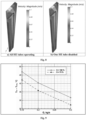
- the following parameters shall be measured in the course of hydraulic testing: the water flow rate in the loop and pressure differential at the inaccessible section.
- Application of the above-mentioned dependence curves enables to determine the actual value of additional flow resistance in the loop according to the point on the plane ⁇ P and G corresponding to the measured values of these parameters.
- the fraction of blocked tubes in relation to their total number in the heat exchanger is determined.
- both water movement through the heat exchanger and heat exchange with the containment medium are going on in the reverse direction as compared with the regular HE operation mode.
- water moves through the heat exchanger from the top downwards and has higher temperature than the containment medium.
- the limit curve shall be plotted in the coordinates of additional flow resistance in the loop ⁇ and the fraction of the "disabled" HE heat exchange surface area ⁇ S.
- the limit curve represents the range of ⁇ and ⁇ S values when the maximum permissible value of pressure under the containment in the course of a severe accident is reached. In relation to the severe accident consequences the limit curve divides the entire range of ⁇ and ⁇ S values into the sub-range of permissible values (under the curve) and impermissible values (above the curve) - see Fig. 2 .
- a diagram for which the values of the parameters are as close to the measured values as possible shall be selected from the series of diagrams.
- Application of the curves on this diagram will enable to determine the relative value of the "disabled" heat exchange surface area, and consequently the number of blocked heat exchange tubes according to the point on the plane ⁇ T and G corresponding to the measured values of these parameters.
- the data obtained at the previous stages are processed, and the state of the passive heat removal system for the internal containment volume is defined.
- the data on the loop resistance ⁇ and the relative value of the "disabled" heat exchange surface ⁇ S obtained in the course of testing shall be compared with the limit curve (see Fig. 2 ). If the point corresponding to the values of these parameters obtained subsequent to processing of the measurement data is below the limit curve, conclusion on the system capability to perform its functions may be made.
- inspection of the heat exchanger tubes shall be carried out in the thermal testing mode (when hot water is flowing through the heat exchanger tubes) with the use of a thermal camera in order to identify sections with relatively low heat emission. Presence of such section in any HE tube may indicate presence of any obstacles for free flow of liquid through this tube.
- Processing of the data obtained at the previous stages and determination of the state of the passive heat removal system for the internal containment volume may be performed with the use of 3D modelling.
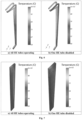
- the computational region represents a segment with a whole tube of type 1 and two halves of a HE tube of type 2 surrounded with air. Water with the specified velocity and temperature is supplied to the inlet boundaries of the HE tubes. Headers supplying water to the HE tubes are not taken into consideration.
- the computational region geometry is presented below in Fig. 3 .
- the cross-section of the computational region is also presented below in Fig. 4 .
- Table 1 The main geometrical characteristics of the computational region are given in Table 1.
- Table 1 Geometrical characteristics of the computational region Total length of a HE tube (with bends), m Length of a vertical HE tube section, m Inner diameter of a HE tube, m Outer diameter of a HE tube, m Thickness of a HE tube, m 5.25 4.62 0.032 0.038 0.003
- Heated water is supplied to the HE tubes with the specified velocity and temperature. Water moves through the HE tubes in the direction opposite to Z axis (from the upper part of the computational region to the lower part) under the impact of forced flow and buoyancy forces in the gravity force field. Zero gage pressure is set at the outlet boundary of the tubes. In case of any counter flow at the outlet boundaries water is supplied with the average temperature at the outlet section of the tube.
- the conjugating boundary conditions shall be set at the phase boundaries between air and steel tubes as well as steel tubes and water. This means equality of temperatures and heat fluxes at the phase boundaries.
- Water is supplied to all 3 tubes of the computational region.
- Heated water is not supplied to one of the tubes.
- the second option simulates potential inoperability of the HE tubes in case of any fouling, incorrect installation of the heat exchanger-condenser and other possible malfunctions.
- the parameters for the second option are obtained subject to the condition that the maximum possible percentage of the HE tube failures is 25% of the total number of tubes in a heat exchanger of the containment PHRS. Given that one heat exchanger - condenser of the containment PHRS contains 132 tubes (100%) the minimum possible number of tubes for the heat exchanger is 99 tubes (75%).
- the numeration of tubes within the computational region taken for convenience is presented in Fig. 5 .
- the tube No. 3 will represent a disabled tube in the calculations.
- the main parameters varying in the calculations include the total water flow rate in the system, i.e. the flow rate for the entire HE (132 tubes) and the water temperature at the inlet of the HE tubes.
- the total water flow rate in the system i.e. the flow rate for the entire HE (132 tubes)
- the water temperature at the inlet of the HE tubes In this case calculation of velocity was performed in the options with a disabled tube due to the fact that the total water flow rate in the system remained constant.
- the option with the temperature at the HE tube inlet T in 100°C was considered in the calculations.
- Radiant heat exchange is taken into account only in the air medium and steel HE tubes. Radiation is not taken into account for the computational region inside the tubes.
- Zero velocity field for water at the temperature of T in is taken as T in of the water medium.
- Flow and heat exchange in the air medium are characterized by the Grashof number Gr, and have the order of Gr ⁇ 1011 for all modes under consideration which is a typical value for free convective turbulent flow.
- the free convective flow around the HE tubes is turbulent, and the semi-empirical standard ⁇ - ⁇ turbulence model with expanded wall-adj acent functions is selected for closure of the Reynolds-averaged Navier-Stokes equations. Buoyancy forces are considered in the Boussinesq approximation.
- S2S Surface-to-Surface model
- the unstructured computational grid with the dimensions of 6.3 mln. cells was plotted for numerical modelling of coupled heat transfer with free and mixed convection.
- Disabling of a tube in the computational model at the inlet water temperature of 100 °C results in velocity increase in all other tubes.
- the water temperature at the tube outlet is higher, and the temperature differential for the option with a disabled tube is lower than for the calculation option with all HE tubes operating.
- the temperature difference between two calculation options for the water temperature of 100 °C at the HE inlet is approximately 5 °C.
- the valves of the heating line and the discharge line shall be closed.
Landscapes
- Engineering & Computer Science (AREA)
- Physics & Mathematics (AREA)
- General Engineering & Computer Science (AREA)
- Plasma & Fusion (AREA)
- High Energy & Nuclear Physics (AREA)
- Monitoring And Testing Of Nuclear Reactors (AREA)
- Thermal Sciences (AREA)
- Mechanical Engineering (AREA)
Applications Claiming Priority (2)
| Application Number | Priority Date | Filing Date | Title |
|---|---|---|---|
| RU2020143962A RU2761866C1 (ru) | 2020-12-30 | 2020-12-30 | Способ мониторинга системы пассивного отвода тепла из внутреннего объема защитной оболочки и устройство для его осуществления |
| PCT/RU2021/000619 WO2022146189A1 (ru) | 2020-12-30 | 2021-12-29 | Способ и устройство мониторинга системы пассивного отвода тепла |
Publications (2)
| Publication Number | Publication Date |
|---|---|
| EP4273885A1 true EP4273885A1 (de) | 2023-11-08 |
| EP4273885A4 EP4273885A4 (de) | 2024-10-16 |
Family
ID=79175201
Family Applications (1)
| Application Number | Title | Priority Date | Filing Date |
|---|---|---|---|
| EP21915939.9A Pending EP4273885A4 (de) | 2020-12-30 | 2021-12-29 | Verfahren und vorrichtung zur überwachung eines passiven wärmeabfuhrsystems |
Country Status (10)
| Country | Link |
|---|---|
| US (1) | US20250273353A1 (de) |
| EP (1) | EP4273885A4 (de) |
| JP (1) | JP7494399B2 (de) |
| KR (1) | KR20230125197A (de) |
| CN (1) | CN116802747A (de) |
| JO (1) | JOP20230154A1 (de) |
| RU (1) | RU2761866C1 (de) |
| SA (1) | SA523441393B1 (de) |
| WO (1) | WO2022146189A1 (de) |
| ZA (1) | ZA202306597B (de) |
Families Citing this family (1)
| Publication number | Priority date | Publication date | Assignee | Title |
|---|---|---|---|---|
| CN115790251A (zh) * | 2022-12-27 | 2023-03-14 | 上海交通大学 | 非均匀加热通道内混合对流换热效率的调控方法及系统 |
Family Cites Families (12)
| Publication number | Priority date | Publication date | Assignee | Title |
|---|---|---|---|---|
| US4571821A (en) * | 1983-08-26 | 1986-02-25 | Westinghouse Electric Corp. | Sleeve insertion |
| RU2082226C1 (ru) * | 1993-10-13 | 1997-06-20 | Опытное конструкторское бюро машиностроения | Система аварийного расхолаживания ядерного реактора |
| RU2302674C1 (ru) * | 2005-12-20 | 2007-07-10 | Федеральное государственное унитарное предприятие "Научно-исследовательский, проектно-конструкторский и изыскательский институт "Атомэнергопроект", ФГУП "Атомэнергопроект" | Система отвода тепла из защитной оболочки |
| RU85029U1 (ru) * | 2009-02-26 | 2009-07-20 | Открытое акционерное общество "Санкт-Петербургский научно-исследовательский и проектно-конструкторский институт "АТОМЭНЕРГОПРОЕКТ" (ОАО "СПбАЭП") | Система пассивного отвода тепла из внутреннего объема защитной оболочки |
| US9536629B2 (en) * | 2012-07-24 | 2017-01-03 | Westinghouse Electric Company Llc | Passive power production during a nuclear station blackout |
| RU2595639C2 (ru) * | 2014-12-04 | 2016-08-27 | Акционерное общество "Научно-исследовательский и проектно-конструкторский институт энергетических технологий "АТОМПРОЕКТ" ("АО "АТОМПРОЕКТ") | Система пассивного отвода тепла из внутреннего объема защитной оболочки |
| RU2595640C2 (ru) * | 2014-12-04 | 2016-08-27 | Акционерное общество "Научно-исследовательский и проектно-конструкторский институт энергетических технологий "АТОМПРОЕКТ" ("АО "АТОМПРОЕКТ") | Система пассивного отвода тепла от водоводяного энергетического реактора через парогенератор |
| KR101651466B1 (ko) * | 2015-04-02 | 2016-08-29 | 한국원자력연구원 | 연구용 원자로 피동잔열제거계통 검증실험장치 |
| WO2017028201A1 (zh) * | 2015-08-18 | 2017-02-23 | 中广核工程有限公司 | 核电站反应堆冷却剂系统主回路的布置结构 |
| CN105070335B (zh) * | 2015-08-24 | 2018-01-09 | 清华大学 | 测量高温高压含尘气流中器件壁面粉尘沉积特性的装置 |
| CN208298560U (zh) * | 2018-07-09 | 2018-12-28 | 中国核动力研究设计院 | 二次侧非能动余热排出系统实验模拟装置 |
| CN110489796B (zh) * | 2019-07-17 | 2022-06-21 | 哈尔滨工程大学 | 一种基于热管的核反应堆热量导出系统的有效性判断方法 |
-
2020
- 2020-12-30 RU RU2020143962A patent/RU2761866C1/ru active
-
2021
- 2021-12-29 EP EP21915939.9A patent/EP4273885A4/de active Pending
- 2021-12-29 CN CN202180088304.6A patent/CN116802747A/zh active Pending
- 2021-12-29 JP JP2023539120A patent/JP7494399B2/ja active Active
- 2021-12-29 KR KR1020237020696A patent/KR20230125197A/ko not_active Ceased
- 2021-12-29 US US18/269,675 patent/US20250273353A1/en active Pending
- 2021-12-29 WO PCT/RU2021/000619 patent/WO2022146189A1/ru not_active Ceased
-
2023
- 2023-06-25 SA SA523441393A patent/SA523441393B1/ar unknown
- 2023-06-25 JO JOJO/P/2023/0154A patent/JOP20230154A1/ar unknown
- 2023-06-27 ZA ZA2023/06597A patent/ZA202306597B/en unknown
Also Published As
| Publication number | Publication date |
|---|---|
| WO2022146189A1 (ru) | 2022-07-07 |
| US20250273353A1 (en) | 2025-08-28 |
| JP7494399B2 (ja) | 2024-06-03 |
| JOP20230154A1 (ar) | 2023-06-25 |
| ZA202306597B (en) | 2024-02-28 |
| RU2761866C1 (ru) | 2021-12-13 |
| JP2024502786A (ja) | 2024-01-23 |
| SA523441393B1 (ar) | 2025-01-07 |
| KR20230125197A (ko) | 2023-08-29 |
| CN116802747A (zh) | 2023-09-22 |
| EP4273885A4 (de) | 2024-10-16 |
Similar Documents
| Publication | Publication Date | Title |
|---|---|---|
| Lee et al. | An experimental study of air–steam condensation on the exterior surface of a vertical tube under natural convection conditions | |
| EP4273885A1 (de) | Verfahren und vorrichtung zur überwachung eines passiven wärmeabfuhrsystems | |
| Juarsa et al. | An experimental analysis on nusselt number of natural circulation flow in transient condition based on the height differences between heater and cooler | |
| He et al. | Experimental research on the thermal and mechanical response of flowing pipelines under the horizontal jet flame | |
| Hong et al. | Heat transfer performance test of PDHRS heat exchangers of PGSFR using STELLA-1 facility | |
| CN209247548U (zh) | 金属保温层抗冲击性能检测装置 | |
| Revankar et al. | Flashing flow of subcooled liquid through small cracks | |
| Lee et al. | Similarity analysis of thermal-fluid flow for thermal testing using scaled-down model of spent fuel storage cask | |
| Revankar et al. | An experimental investigation of subcooled choked flow in actual steam generator tube cracks | |
| Albdour et al. | Thermal performance analysis of reflux condensation in vertical tubes via pure steam | |
| Wu | Horizontal in-tube condensation in the presence of a noncondensable gas | |
| Heffner et al. | SPERT III reactor facility | |
| Wiltschko et al. | Experimental investigation of heat transfer to supercritical pressure R134a in artificially roughened tubes | |
| Lee et al. | Interfacial condensation for countercurrent steam–water stratified wavy flow in a horizontal circular pipe | |
| EA047072B1 (ru) | Система пассивного отвода тепла из внутреннего объема защитной оболочки и способ ее мониторинга | |
| Revankar et al. | INVESTIGATION OF subscriptCOOLEDWATER DISCHARGE THROUGH SIMULATED STEAM GENERATOR TUBE CRACKS | |
| Schmitt et al. | SIMULATED DESIGN BASIS ACCIDENT TESTS OF THE CAROLINAS VIRGINIA TUBE REACTOR CONTAINMENT. Final Report. | |
| Lim et al. | Single-phase heat transfer in the high temperature multiple porous insulation | |
| Vierow | Countercurrent flow limitation experiments and modeling for improved reactor safety | |
| Hannink et al. | Modelling of thermal loads of the surge line of a PWR | |
| DeBear et al. | Operating experience and sodium-water reaction testing in the large leak test rig | |
| Casey | High pressure condensation heat transfer in the evacuated containment of a small modular reactor | |
| Moe et al. | A comparison of experimental data and CFD predicted cool down in subsea equipment | |
| Nam et al. | Flow analysis and test for ITER thermal shield components | |
| Lim | Heat transfer properties of porous insulation used in Magnox reactors |
Legal Events
| Date | Code | Title | Description |
|---|---|---|---|
| STAA | Information on the status of an ep patent application or granted ep patent |
Free format text: STATUS: THE INTERNATIONAL PUBLICATION HAS BEEN MADE |
|
| PUAI | Public reference made under article 153(3) epc to a published international application that has entered the european phase |
Free format text: ORIGINAL CODE: 0009012 |
|
| STAA | Information on the status of an ep patent application or granted ep patent |
Free format text: STATUS: REQUEST FOR EXAMINATION WAS MADE |
|
| 17P | Request for examination filed |
Effective date: 20230628 |
|
| AK | Designated contracting states |
Kind code of ref document: A1 Designated state(s): AL AT BE BG CH CY CZ DE DK EE ES FI FR GB GR HR HU IE IS IT LI LT LU LV MC MK MT NL NO PL PT RO RS SE SI SK SM TR |
|
| DAV | Request for validation of the european patent (deleted) | ||
| DAX | Request for extension of the european patent (deleted) | ||
| A4 | Supplementary search report drawn up and despatched |
Effective date: 20240912 |
|
| RIC1 | Information provided on ipc code assigned before grant |
Ipc: G21D 3/00 20060101ALI20240906BHEP Ipc: G21C 15/18 20060101ALI20240906BHEP Ipc: G06F 30/17 20200101ALI20240906BHEP Ipc: G21C 17/10 20060101ALI20240906BHEP Ipc: G21C 15/00 20060101AFI20240906BHEP |
|
| GRAP | Despatch of communication of intention to grant a patent |
Free format text: ORIGINAL CODE: EPIDOSNIGR1 |
|
| STAA | Information on the status of an ep patent application or granted ep patent |
Free format text: STATUS: GRANT OF PATENT IS INTENDED |
|
| INTG | Intention to grant announced |
Effective date: 20251126 |