EP4273973B1 - Separator für brennstoffzelle und brennstoffzellenstapel - Google Patents
Separator für brennstoffzelle und brennstoffzellenstapel Download PDFInfo
- Publication number
- EP4273973B1 EP4273973B1 EP22185409.4A EP22185409A EP4273973B1 EP 4273973 B1 EP4273973 B1 EP 4273973B1 EP 22185409 A EP22185409 A EP 22185409A EP 4273973 B1 EP4273973 B1 EP 4273973B1
- Authority
- EP
- European Patent Office
- Prior art keywords
- hole
- plate body
- separator
- reinforcing member
- cap portion
- Prior art date
- Legal status (The legal status is an assumption and is not a legal conclusion. Google has not performed a legal analysis and makes no representation as to the accuracy of the status listed.)
- Active
Links
Images


Classifications
-
- H—ELECTRICITY
- H01—ELECTRIC ELEMENTS
- H01M—PROCESSES OR MEANS, e.g. BATTERIES, FOR THE DIRECT CONVERSION OF CHEMICAL ENERGY INTO ELECTRICAL ENERGY
- H01M8/00—Fuel cells; Manufacture thereof
- H01M8/02—Details
- H01M8/0271—Sealing or supporting means around electrodes, matrices or membranes
-
- H—ELECTRICITY
- H01—ELECTRIC ELEMENTS
- H01M—PROCESSES OR MEANS, e.g. BATTERIES, FOR THE DIRECT CONVERSION OF CHEMICAL ENERGY INTO ELECTRICAL ENERGY
- H01M4/00—Electrodes
- H01M4/86—Inert electrodes with catalytic activity, e.g. for fuel cells
- H01M4/88—Processes of manufacture
- H01M4/8803—Supports for the deposition of the catalytic active composition
- H01M4/8807—Gas diffusion layers
-
- H—ELECTRICITY
- H01—ELECTRIC ELEMENTS
- H01M—PROCESSES OR MEANS, e.g. BATTERIES, FOR THE DIRECT CONVERSION OF CHEMICAL ENERGY INTO ELECTRICAL ENERGY
- H01M8/00—Fuel cells; Manufacture thereof
- H01M8/02—Details
- H01M8/0202—Collectors; Separators, e.g. bipolar separators; Interconnectors
-
- H—ELECTRICITY
- H01—ELECTRIC ELEMENTS
- H01M—PROCESSES OR MEANS, e.g. BATTERIES, FOR THE DIRECT CONVERSION OF CHEMICAL ENERGY INTO ELECTRICAL ENERGY
- H01M8/00—Fuel cells; Manufacture thereof
- H01M8/02—Details
- H01M8/0202—Collectors; Separators, e.g. bipolar separators; Interconnectors
- H01M8/023—Porous and characterised by the material
- H01M8/0234—Carbonaceous material
-
- H—ELECTRICITY
- H01—ELECTRIC ELEMENTS
- H01M—PROCESSES OR MEANS, e.g. BATTERIES, FOR THE DIRECT CONVERSION OF CHEMICAL ENERGY INTO ELECTRICAL ENERGY
- H01M8/00—Fuel cells; Manufacture thereof
- H01M8/02—Details
- H01M8/0202—Collectors; Separators, e.g. bipolar separators; Interconnectors
- H01M8/0258—Collectors; Separators, e.g. bipolar separators; Interconnectors characterised by the configuration of channels, e.g. by the flow field of the reactant or coolant
-
- H—ELECTRICITY
- H01—ELECTRIC ELEMENTS
- H01M—PROCESSES OR MEANS, e.g. BATTERIES, FOR THE DIRECT CONVERSION OF CHEMICAL ENERGY INTO ELECTRICAL ENERGY
- H01M8/00—Fuel cells; Manufacture thereof
- H01M8/02—Details
- H01M8/0271—Sealing or supporting means around electrodes, matrices or membranes
- H01M8/0273—Sealing or supporting means around electrodes, matrices or membranes with sealing or supporting means in the form of a frame
-
- H—ELECTRICITY
- H01—ELECTRIC ELEMENTS
- H01M—PROCESSES OR MEANS, e.g. BATTERIES, FOR THE DIRECT CONVERSION OF CHEMICAL ENERGY INTO ELECTRICAL ENERGY
- H01M8/00—Fuel cells; Manufacture thereof
- H01M8/02—Details
- H01M8/0271—Sealing or supporting means around electrodes, matrices or membranes
- H01M8/0276—Sealing means characterised by their form
-
- H—ELECTRICITY
- H01—ELECTRIC ELEMENTS
- H01M—PROCESSES OR MEANS, e.g. BATTERIES, FOR THE DIRECT CONVERSION OF CHEMICAL ENERGY INTO ELECTRICAL ENERGY
- H01M8/00—Fuel cells; Manufacture thereof
- H01M8/10—Fuel cells with solid electrolytes
- H01M8/1004—Fuel cells with solid electrolytes characterised by membrane-electrode assemblies [MEA]
-
- H—ELECTRICITY
- H01—ELECTRIC ELEMENTS
- H01M—PROCESSES OR MEANS, e.g. BATTERIES, FOR THE DIRECT CONVERSION OF CHEMICAL ENERGY INTO ELECTRICAL ENERGY
- H01M8/00—Fuel cells; Manufacture thereof
- H01M8/24—Grouping of fuel cells, e.g. stacking of fuel cells
- H01M8/241—Grouping of fuel cells, e.g. stacking of fuel cells with solid or matrix-supported electrolytes
-
- H—ELECTRICITY
- H01—ELECTRIC ELEMENTS
- H01M—PROCESSES OR MEANS, e.g. BATTERIES, FOR THE DIRECT CONVERSION OF CHEMICAL ENERGY INTO ELECTRICAL ENERGY
- H01M8/00—Fuel cells; Manufacture thereof
- H01M8/10—Fuel cells with solid electrolytes
- H01M2008/1095—Fuel cells with polymeric electrolytes
-
- H—ELECTRICITY
- H01—ELECTRIC ELEMENTS
- H01M—PROCESSES OR MEANS, e.g. BATTERIES, FOR THE DIRECT CONVERSION OF CHEMICAL ENERGY INTO ELECTRICAL ENERGY
- H01M8/00—Fuel cells; Manufacture thereof
- H01M8/02—Details
- H01M8/0202—Collectors; Separators, e.g. bipolar separators; Interconnectors
- H01M8/0204—Non-porous and characterised by the material
- H01M8/0206—Metals or alloys
-
- Y—GENERAL TAGGING OF NEW TECHNOLOGICAL DEVELOPMENTS; GENERAL TAGGING OF CROSS-SECTIONAL TECHNOLOGIES SPANNING OVER SEVERAL SECTIONS OF THE IPC; TECHNICAL SUBJECTS COVERED BY FORMER USPC CROSS-REFERENCE ART COLLECTIONS [XRACs] AND DIGESTS
- Y02—TECHNOLOGIES OR APPLICATIONS FOR MITIGATION OR ADAPTATION AGAINST CLIMATE CHANGE
- Y02E—REDUCTION OF GREENHOUSE GAS [GHG] EMISSIONS, RELATED TO ENERGY GENERATION, TRANSMISSION OR DISTRIBUTION
- Y02E60/00—Enabling technologies; Technologies with a potential or indirect contribution to GHG emissions mitigation
- Y02E60/30—Hydrogen technology
- Y02E60/50—Fuel cells
Definitions
- the present disclosure relates to a separator for a fuel cell and a fuel cell stack, and more particularly, to a separator for a fuel cell and a fuel cell stack, which are capable of improving performance and operational efficiency.
- a fuel cell stack refers to a kind of power generation device that generates electrical energy through a chemical reaction of fuel (e.g., hydrogen), and the fuel cell stack may be configured by stacking several tens or hundreds of fuel cells (unit cells) in series.
- fuel e.g., hydrogen
- the fuel cell may include a membrane electrode assembly (MEA) having an electrolyte membrane configured to allow hydrogen positive ions to move therethrough, and electrodes (catalyst electrode layers) provided on two opposite surfaces of the electrolyte membrane and configured to enable a reaction between hydrogen and oxygen.
- MEA membrane electrode assembly
- the fuel cell may also include gas diffusion layers (GDLs) disposed to be in close contact with two opposite surfaces of the membrane electrode assembly and configured to distribute reactant gases and transfer the generated electrical energy, and separators (bipolar plates) disposed to be in close contact with the gas diffusion layers and configured to define flow paths.
- GDLs gas diffusion layers
- the separators may include an anode separator configured to supply hydrogen which is fuel, and a cathode separator configured to supply air which is an oxidant.
- the separator includes channels through which the fuel or the oxidant flows.
- sealability needs to be maintained between the membrane electrode assembly and reaction surfaces of the separators and between cooling surfaces of the separators.
- gaskets are disposed between the membrane electrode assembly and the reaction surfaces of the separators and the cooling surfaces of the separators. That is, the gaskets serve to prevent the reactant gases (e.g., hydrogen and air) flowing to the reaction surfaces of the separators from leaking to the outside of the fuel cell stack and to prevent the coolant flowing to the cooling surfaces of the separators from leaking to the outside of the fuel cell stack.
- reactant gases e.g., hydrogen and air
- the gaskets may be integrated, by injection molding, with edge portions of two opposite surfaces of the separator and with edge portions of two opposite sides of each manifold for allowing the reactant gases and the coolant to flow in and out.
- the flow paths for the reactant gases and the coolant may be defined by the gaskets.
- the reactant gas introduced into the through-hole needs to flow to the reaction region while inevitably passing through the compressed gas diffusion layer. For this reason, there are problems in that fluidity and flow efficiency of the reactant gas (or the coolant) passing through the through-hole deteriorate, and a differential pressure between the two opposite ends (an inlet end and an outlet end) of the manifold flow path increases.
- EP 2 573 851 A2 which generally relates to a metal separator for fuel cell and fuel cell stack having the same
- JP 2012 248472 A which generally relates to a fuel cell separator plate, fuel cell separator, fuel cell, and manufacturing method of fuel cell separator plate
- US 2019/221866 A1 which generally relates to electrochemical cells with improved fluid flow design.
- the present disclosure has been made in an effort to provide a separator for a fuel cell and a fuel cell stack, which are capable of ensuring smooth flows of reactant gases and a smooth flow of a coolant and improving safety and reliability.
- the present disclosure has also been made in an effort to improve flow efficiency and enable reactant gases and a coolant to stably flow through through-holes for guiding the reactant gases and the coolant introduced through manifold flow paths of a separator to a reaction region.
- the present disclosure has also been made in an effort to inhibit a sealing member from being excessively compressed (being deformed) and stably ensure flow path areas through which reactant gases and a coolant having passed through through-holes flow.
- the present disclosure has also been made in an effort to ensure sealability (fastening performance) between fuel cells while ensuring flows of reactant gases and a flow of a coolant.
- the present disclosure has also been made in an effort to simplify a structure and a manufacturing process and reduce manufacturing costs.
- the present disclosure has also been made in an effort to minimize a distribution deviation (flow rate deviation) of a reactant gas or a coolant and ensure stable output performance.
- a separator for a fuel cell which is configured to be stacked on a gas diffusion layer provided on a membrane electrode assembly, MEA
- the separator comprising: a plate body configured to be stacked on the gas diffusion layer and comprising a flow path part configured to define a reaction region configured to react with the membrane electrode assembly, and manifold parts spaced apart from the flow path part; through-holes disposed in the plate body and configured to guide target fluids that have passed through the manifold parts to the flow path part; hole caps disposed on one surface of the plate body that faces the gas diffusion layer and configured to at least partially cover the through-holes, the hole caps being configured to define movement paths through which the target fluids move, wherein each hole cap comprises: a side cap portion disposed on an edge of the respective through-hole; and a top cap portion spaced apart from the plate body, configured to cover the respective through-hole, and supported by the side cap portion, wherein the movement path is defined in a space between the top cap portion and the plate body
- gaskets provided on two opposite surfaces of a separator are deformed (excessively compressed) when fastening pressure (pressing force) is applied to a fuel cell.
- a portion of the gasket (sealing member) which is disposed around a through-hole for guiding the reactant gas (or the coolant) introduced through the manifold flow path to a reaction region on the separator, is excessively compressed, which makes it difficult to ensure a sufficient flow path (cross-sectional area of the flow path) for the reactant gas or the coolant. For this reason, it is difficult to smoothly supply the reactant gas or the coolant to the reaction region on the separator (a channel between an inlet manifold and an outlet manifold).
- the reactant gas introduced into the through-hole needs to flow to the reaction region while inevitably passing through the compressed gas diffusion layer. For this reason, there are problems in that fluidity and flow efficiency of the reactant gas (or the coolant) passing through the through-hole deteriorate, and a differential pressure between the two opposite ends (an inlet end and an outlet end) of the manifold flow path increases.
- the hole cap is disposed to cover the through-hole, and the hole cap defines the movement path which is not blocked by the gas diffusion layer. Therefore, it is possible to ensure the fluidity and flow efficiency of the reactant gas (or coolant) passing through the through-hole and ensure stable output performance of the fuel cell stack.
- the hole cap may support the gas diffusion layer, such that it is possible to inhibit the portion of the sealing member, which is disposed around the through-hole, from being excessively compressed. Therefore, it is possible to obtain an advantageous effect of ensuring sealability (fastening performance) of the fuel cell and ensuring sufficient flow paths (flow path cross-sectional areas) for the reactant gases and the coolant.
- the separator for a fuel cell may include a sealing member provided on the plate body and configured to seal a portion between the adjacent through-holes, the sealing member being configured to define a distribution channel configured to connect the flow path part and the through-hole so that the flow path part and the through-hole communicate with each other, in which the hole cap is positioned in the distribution channel.
- the hole cap may have various structures having the movement path.
- the hole cap includes: a side cap portion provided on an edge of the through-hole; and a top cap portion spaced apart from the plate body, configured to cover the through-hole, and supported by the side cap portion, and the movement path is defined in a space between the top cap portion and the plate body.
- the movement path may be defined to be parallel to the plate body.
- the hole cap may be integrated with the plate body by partially processing a part of the plate body.
- the hole cap may be formed at the time of forming separator (during the process of forming the flow path). Therefore, it is possible to obtain an advantageous effect of simplifying the structure and manufacturing process and reducing the costs.
- the separator for a fuel cell may include a side hole penetratively formed in a wall surface of the side cap portion.
- the side hole may be provided in the side cap portion. Therefore, it is possible to obtain an advantageous effect of ensuring a smoother flow of the target fluid passing through the through-hole and reducing the occurrence of differential pressure in the through-hole.
- the separator for a fuel cell includes a reinforcing part configured to support the hole cap on the plate body.
- the reinforcing part may have various structures capable of supporting the hole cap on the plate body.
- the reinforcing part may be disposed in the through-hole.
- the reinforcing part includes: a center reinforcing member connected to an inner surface of the top cap portion; a first side reinforcing member having one end connected to one side surface of the center reinforcing member and the other end connected to the plate body; and a second side reinforcing member having one end connected to the other side surface of the center reinforcing member and the other end connected to the plate body.
- the first side reinforcing member may be provided in plural, the plurality of first side reinforcing members may be spaced apart from one another in a longitudinal direction of the center reinforcing member, the second side reinforcing member may be provided in plural, and the plurality of second side reinforcing members may be spaced apart from one another in the longitudinal direction of the center reinforcing member.
- the plurality of first side reinforcing members and the plurality of second side reinforcing members may be spaced apart from one another in the longitudinal direction of the center reinforcing member. Therefore, it is possible to ensure a smooth flow of the target fluid while more stably supporting the center reinforcing member.
- the separator for a fuel cell may include a center hole provided in the center reinforcing member and formed through one side surface and the other side surface of the center reinforcing member.
- the center hole may be provided in the center reinforcing member. Therefore, it is possible to obtain an advantageous effect of minimizing a decrease in flow of the target fluid caused by the center reinforcing member provided in the hole cap.
- a fuel cell stack comprising: a membrane electrode assembly, MEA; a gas diffusion layer stacked on the membrane electrode assembly; and a separator comprising: a plate body configured to be stacked on the gas diffusion layer and comprising a flow path part configured to define a reaction region configured to react with the membrane electrode assembly, and manifold parts spaced apart from the flow path part; through-holes disposed in the plate body and configured to guide target fluids that have passed through the manifold parts to the reaction region; hole caps disposed on one surface of the plate body that faces the gas diffusion layer and configured to at least partially cover the through-holes, the hole caps being configured to define movement paths through which the target fluids move, wherein each hole cap comprises: a side cap portion disposed on an edge of the respective through-hole; and a top cap portion spaced apart from the plate body, configured to cover the respective through-hole, and supported by the side cap portion, wherein the movement path is defined in a space between the top cap portion and the plate body, and
- the hole cap includes: a side cap portion provided on an edge of the through-hole; and a top cap portion spaced apart from the plate body, configured to cover the through-hole, and supported by the side cap portion, and the movement path is defined in a space between the top cap portion and the plate body.
- the fuel cell stack may include a side hole penetratively formed in a wall surface of the side cap portion.
- the fuel cell stack includes a reinforcing part configured to support the hole cap on the plate body.
- the reinforcing part includes: a center reinforcing member connected to an inner surface of the top cap portion; a first side reinforcing member having one end connected to one side surface of the center reinforcing member and the other end connected to the plate body; and a second side reinforcing member having one end connected to the other side surface of the center reinforcing member and the other end connected to the plate body.
- the fuel cell stack may include a center hole provided in the center reinforcing member and formed through one side surface and the other side surface of the center reinforcing member.
- the fuel cell stack may include a sealing member provided on the plate body and configured to seal a portion between the adjacent through-holes, the sealing member being configured to define a distribution channel configured to connect the flow path part and the through-hole so that the flow path part and the through-hole communicate with each other, in which the hole cap is positioned in the distribution channel.
- the hole cap may be integrated with the plate body by partially processing a part of the plate body.
- a singular form may also include a plural form.
- the expression "at least one (or one or more) of A, B, and C" may include one or more of all combinations that can be made by combining A, B, and C.
- first, second, A, B, (a), and (b) may be used to describe constituent elements of the embodiments of the present disclosure.
- one constituent element when one constituent element is described as being 'connected', 'coupled', or 'attached' to another constituent element, one constituent element may be connected, coupled, or attached directly to another constituent element or connected, coupled, or attached to another constituent element through still another constituent element interposed therebetween.
- one constituent element is provided or disposed above (on) or below (under) another constituent element” includes not only a case in which the two constituent elements are in direct contact with each other, but also a case in which one or more other constituent elements are provided or disposed between the two constituent elements.
- the expression “above (on) or below (under)” may mean a downward direction as well as an upward direction based on one constituent element.
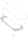
- a fuel cell stack 10 includes: a membrane electrode assembly (MEA) 300; a gas diffusion layer 200 stacked on the membrane electrode assembly 300; and a separator 100 including: a plate body 110 stacked on the gas diffusion layer 200 and including a flow path part 101 configured to define a reaction region configured to react with the membrane electrode assembly 300, and manifold parts 102 spaced apart from the flow path part 101; through-holes 112 formed in the plate body 110 and configured to guide target fluids (e.g., reactant gases and a coolant) having passed through the manifold parts 102 to the reaction region; and hole caps 120 disposed on one surface of the plate body 110 facing the gas diffusion layer 200 and configured to at least partially cover the through-holes 112, the hole caps 120 being configured to define movement paths 120a through which the target fluids move.
- target fluids e.g., reactant gases and a coolant
- the fuel cell stack 10 may be configured by stacking a plurality of unit cells in a reference direction (e.g., an upward/downward direction).
- the fuel cell (unit cell) may include a reaction layer (not illustrated), and the separators 100 stacked on two respective opposite sides of the reaction layer.
- the fuel cell stack 10 may be configured by stacking the plurality of fuel cells in the reference direction and then assembling end plates (not illustrated) to the two opposite ends of the plurality of fuel cells.
- the reaction layer may include the membrane electrode assembly (MEA) 300, and the gas diffusion layers (GDL) 200 being in close contact with two opposite sides of the membrane electrode assembly 300.
- MEA membrane electrode assembly
- GDL gas diffusion layers
- the membrane electrode assembly 300 serves to generate electricity by means of an oxidation-reduction reaction between fuel (e.g., hydrogen), which is a first reactant gas, and an oxidant (e.g., air) which is a second reactant gas.
- fuel e.g., hydrogen
- oxidant e.g., air
- the membrane electrode assembly 300 may be variously changed in structure and material in accordance with required conditions and design specifications, and the present disclosure is not limited or restricted by the structure and material of the membrane electrode assembly 300.
- the membrane electrode assembly 300 includes the electrolyte membrane through which hydrogen ions move, and the catalyst electrode layers attached to two opposite surfaces of the electrolyte membrane, and the electrochemical reactions occur in the catalyst electrode layers.
- the gas diffusion layers (GDLs) 200 are stacked on the two opposite sides of the membrane electrode assembly 300 and serve to uniformly distribute the reactant gases and transfer the produced electrical energy.
- the gas diffusion layer 200 may have various structures capable of diffusing the reactant gas.
- the gas diffusion layer 200 may have a porous structure having pores each having a predetermined size.
- the sizes of the pores and the material of the gas diffusion layer 200 may be variously changed in accordance with required conditions and design specifications, and the present disclosure is not limited or restricted by the sizes of the pores and the material of the gas diffusion layer 200.
- the separators 100 are provided to serve not only to block (separate) hydrogen and air, which are the reactant gases, but also to ensure flow paths of the reactant gases and the coolant and transmit electric current to an external circuit.
- the separators 100 may also serve to distribute heat, which is generated in the fuel cell (unit cell), to the entire fuel cell, and the excessively generated heat may be discharged to the outside by a coolant flowing along the cooling channels between the separators 100.
- the separators 100 may be defined as including both an anode separator having flow paths for hydrogen which is fuel, and a cathode separator having flow paths for air which is an oxidant.
- hydrogen which is the fuel
- air which is the oxidant
- an anode (not illustrated) and a cathode (not illustrated) of the membrane electrode assembly 300, respectively, through the channels in the separators 100 (the cathode separator and the anode separator).
- the hydrogen may be supplied to the anode, and the air may be supplied to the cathode.
- the hydrogen supplied to the anode is separated into hydrogen ions (protons) and electrons by catalysts in the electrode layers respectively provided on the two opposite sides of the electrolyte membrane. Only the hydrogen ions are selectively transmitted to the cathode through the electrolyte membrane, which is a cation exchange membrane, and at the same time, the electrons are transmitted to the cathode through the gas diffusion layer 200 and the separator 100 which are conductors.
- the hydrogen ions supplied through the electrolyte membrane and the electrons transmitted through the separator 100 meet oxygen in the air supplied to the cathode by an air supply device, thereby creating a reaction of producing water.
- the electrons flow through external conductive wires, and the electric current is generated as a result of the flow of the electrons.
- the separators 100 are configured to supply the first reactant gas (e.g., hydrogen) and the second reactant gas (e.g., air) to the membrane electrode assembly 300, and disposed to be in close contact with one side and the other side of the membrane electrode assembly 300 (an outer surface of the gas diffusion layer) in a direction in which the fuel cells are stacked.
- first reactant gas e.g., hydrogen
- second reactant gas e.g., air
- the separator 100 includes: the plate body 110 stacked on the gas diffusion layer 200 and including the flow path part 101 configured to define the reaction region configured to react with the membrane electrode assembly 300, and the manifold parts 102 spaced apart from the flow path part 101; the through-holes 112 formed in the plate body 110 and configured to guide the target fluids having passed through the manifold parts 102 to the flow path parts 101; and the hole caps 120 disposed on one surface of the plate body 110 facing the gas diffusion layer 200 and configured to at least partially cover the through-holes 112, the hole caps 120 being configured to define the movement paths 120a through which the target fluids move.
- the plate body 110 may be provided in the form of a flat, thin film plate, and the present disclosure is not limited or restricted by the size, material, and structure of the plate body 110.
- the plate body 110 may be provided in the form of an approximately flat quadrangular plate and made of a typical metal material (e.g., stainless steel, Inconel, or aluminum).
- the plate body may be made of another material such as graphite or a carbon composite.
- the flow path part 101 is disposed at an approximately central portion of the plate body 110 and faces one surface of the membrane electrode assembly 300 to define the reaction region.
- the flow path part 101 may include a plurality of flow paths (channels, not illustrated) disposed to be spaced apart from one another.
- the present disclosure is not restricted or limited by the number of flow paths and the arrangement structure of the flow paths.
- the manifold parts 102 e.g., a hydrogen manifold, a coolant manifold, and an air manifold
- the manifold parts 102 are penetratively provided at two opposite ends of the separator 100 with the flow path part 101 interposed therebetween, and the manifold parts 102 serve to move (supply and discharge) the hydrogen, the air, and the coolant, respectively.
- a first manifold (not illustrated) may be disposed at one end of the separator 100 and spaced apart from one end of the flow path part 101
- a second manifold (not illustrated) may be disposed at the other end of the separator 100 and spaced apart from the other end of the flow path part 101.
- the target fluids e.g., the reactant gases and the coolant
- the target fluids may be introduced into any one of the first manifold and the second manifold, and the target fluids may be discharged from the other of the first manifold and the second manifold.
- the first manifold may include a hydrogen inlet manifold through which the hydrogen is supplied, a coolant inlet manifold through which the coolant is supplied, and an air outlet manifold through which the air is discharged.
- the second manifold may include a hydrogen outlet manifold through which the hydrogen is discharged, a coolant outlet manifold through which the coolant is discharged, and an air inlet manifold through which the air is supplied.
- the manifold part 102 may be variously changed in structure and shape in accordance with required conditions and design specifications. The present disclosure is not restricted or limited by the structure and shape of the manifold part 102.
- the hydrogen inlet manifold, the coolant inlet manifold, and the air outlet manifold may each be penetratively provided at one end of the separator 100 and have an approximately trapezoidal or triangular shape.
- the hydrogen outlet manifold, the coolant outlet manifold, and the air inlet manifold may each be penetratively provided at the other end of the separator 100 and have an approximately trapezoidal or triangular shape.
- the through-holes 112 are provided in the plate body 110 and positioned between the manifold parts 102 and the flow path part 101.
- the through-hole 112 is penetratively provided in the plate body 110 and guides the target fluid having passed through the manifold part 102 to the flow path part 101.
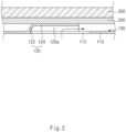
- the reactant gas (e.g., hydrogen) supplied through the manifold part 102 may be supplied to the through-holes 112 along a movement route (not illustrated) defined on one surface (e.g., a bottom surface based on FIG. 2 ) of the separator 100.
- the reactant gas having passed through the through-holes 112 may be supplied to the flow path part 101 along distribution channels 132 defined on the other surface (e.g., a top surface based on FIG. 2 ) of the separator 100.
- the through-hole 112 may have various shape in accordance with required conditions and design specifications. The present disclosure is not restricted or limited by the structure and shape of the through-hole 112.
- the through hole 112 may be provided in the form of a long hole with a length longer than a width thereof.
- the through-hole 112 may have a circular or other shapes.
- the fuel cell stack 10 may include a sealing member 130 disposed on the plate body 110 and configured to seal portions between the adjacent through-holes 112 and define the distribution channels 132 configured to connect the flow path part 101 and the through-holes 112 so that the flow path part 101 and the through-holes 112 communicate with one another.
- the sealing member 130 may be disposed on the plate body 110 and configured to seal the portions between the adjacent through-holes 112 while sealing the portions between the membrane electrode assembly 300 and the separator 100.
- the plurality of distribution channels 132 may be defined between the membrane electrode assembly 300 and the separator 100 by means of the sealing member 130 and connect the flow path part 101 and the through-holes 112 so that the flow path part 101 and the through-holes 112 communicate with one another. Further, the hole caps 120 may be positioned in the distribution channels 132.
- the plurality of distribution channels 132 is spaced apart from the through-holes 112, respectively, at predetermined intervals. One end of each of the distribution channels 132 communicates with the manifold part 102 through the through-hole 112, the other end of each of the distribution channel 132 communicates with the flow path part 101.
- the distribution channel 132 may be variously changed in number, width, and spacing interval in accordance with required conditions and design specifications. The present disclosure is not restricted or limited by the number of distribution channels 132, the width of the distribution channel 132, and the spacing interval between the distribution channels 132.
- the sealing member 130 may be manufactured in various ways in accordance with required conditions and design specifications, and the present disclosure is not restricted or limited by the method of manufacturing the sealing member 130.
- the sealing member 130 may be manufactured by applying or transferring a sealant made of an elastic material such as rubber, silicone, or urethane onto the surface of the plate body 110 or performing a printing process on the surface of the plated body 110 with the sealant.
- a sealant made of an elastic material such as rubber, silicone, or urethane
- the sealing member may be attached to the plate body by injection molding.
- the sealing member may be manufactured (by injection molding, for example) separately from the plate body and then attached (bonded) to the plate body.
- the hole cap 120 is provided on one surface of the plate body 110 facing the gas diffusion layer 200 and covers at least a part of the through-hole 112.
- the movement path 120a through which the target fluid (the reactant gas or the coolant) moves is defined between the gas diffusion layer 200 and the plate body 110 by means of the hole cap 120.
- the hole cap 120 serves to stably ensure fluidity and flow efficiency of the target fluid passing through the through-hole 112.
- the entire through-hole is covered by the gas diffusion layer (the gas diffusion layer is inserted into the through-hole to block the through-hole) in the state in which the separator is stacked on the gas diffusion layer, and the reactant gas introduced into the through-hole needs to flow to the reaction region while inevitably passing through the compressed gas diffusion layer. For this reason, there is a problem in that fluidity and flow efficiency of the target fluid deteriorate.
- the hole cap 120 may cover the through-hole 112, and the hole cap 120 may define the movement path 120a which is not blocked by the gas diffusion layer 200. Therefore, it is possible to ensure the fluidity and flow efficiency of the reactant gas (or coolant) passing through the through-hole 112 and ensure stable output performance of the fuel cell stack 10.
- the hole cap 120 may inhibit the portion of the sealing member 130, which is disposed around the through-hole 112, from being excessively compressed at the time of applying the fastening pressure to the fuel cell stack 10 (the hole cap 120 may maintain a width of the distribution channel while supporting the sealing member 130 which is compressed to a certain level or higher). Therefore, it is possible to obtain an advantageous effect of ensuring sealability of the fuel cell and ensuring sufficient flow paths (flow path cross-sectional areas) for the reactant gases and the coolant. Therefore, it is possible to obtain an advantageous effect of minimizing a deviation between flow rates of the target fluids supplied to the flow paths of the flow path part 101 and ensuring stable and uniform output performance of the fuel cell stack 10.
- the hole cap 120 may have various structures having the movement path 120a. The present disclosure is not restricted or limited by the structure and shape of the hole cap 120.
- the hole cap 120 may include a side cap portion 122 provided on an edge of the through-hole 112, and a top cap portion 124 spaced apart from the plate body 110, configured to cover the through-hole 112, and supported by the side cap portion 122.
- the movement path 120a may be defined in a space between the top cap portion 124 and the plate body 110.
- the movement path 120a may be understood as a vacant space defined in the hole cap 120.
- the movement path 120a may have various structures in accordance with required conditions and design specifications. According to the exemplary embodiment of the present disclosure, the movement path 120a may be defined to be approximately parallel to the plate body 110. According to another embodiment of the present disclosure, the movement path may have a curved shape or other shapes.
- the side cap portion 122 may have various structures having an opening portion that communicates with the flow path part 101 (the distribution channel).
- the side cap portion 122 may be continuously provided along the edge of the through-hole 112.
- the side cap portion 122 may be provided in a continuous "C" shape along the edge of the through-hole 112.
- the side cap portion 122 is provided in the form of a continuous band.
- a plurality of side cap portions may be provided to be spaced apart from one another along the edge of the through-hole.
- the top cap portion 124 is supported on an end of the side cap portion 122 so as to be spaced apart from the plate body 110.
- the top cap portion 124 and the side cap portion 122 collectively define the movement path 120a.
- the top cap portion 124 may be provided in the form of an approximately flat plate.
- the top cap portion 124 and the side cap portion 122 may collectively define an approximately "U" cross-sectional shape.
- the gas diffusion layer 200 may be supported on an outer surface (top surface based on FIG. 2 ) of the top cap portion 124.
- the target fluid having passed through the through-hole 112 may move along the internal space (movement path) of the top cap portion 124.
- the top cap portion 124 may be variously changed in size in accordance with required conditions and design specifications. The present disclosure is not restricted or limited by the size of the top cap portion 124.
- the top cap portion 124 may have a size (an area being in contact with the gas diffusion layer) corresponding to 50% or more of an overall area of the through-hole 112.
- the top cap portion 124 may have a size corresponding to less than 50% (e.g., 25%) of the overall area of the through-hole 112. However, if the size of the top cap portion 124 is less than 50% of the overall area of the through-hole 112, it is difficult to effectively support the portion of the sealing member 130 disposed around the through-hole 112 (it is difficult to inhibit the sealing member from being excessively compressed). Therefore, the top cap portion 124 may have a size corresponding to 50% or more of the overall area of the through-hole 112.
- the hole cap 120 may be provided in various ways in accordance with required conditions and design specifications.
- the hole cap 120 may be integrated with the plate body 110 by partially processing (e.g., pressing) a part of the plate body 110.
- the hole cap 120 may be formed together with the flow path (through a single process) when the flow path (channel) is formed by partially processing a part of the plate body 110.
- the hole cap 120 may be formed at the time of forming separator 100 (e.g., during the process of forming the flow path). Therefore, it is possible to obtain an advantageous effect of simplifying the structure and manufacturing process and reducing the costs.
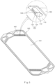
- the fuel cell stack 10 may include side holes 126 penetratively formed in a wall surface of the side cap portion 122.
- the side hole 126 may have various structures in accordance with required conditions and design specifications. The present disclosure is not restricted or limited by the structure of the side hole 126.
- the side hole 126 may be provided in the form of an approximately circular hole.
- the side hole 126 may be provided in plural, and the plurality of side holes 126 may be spaced apart from one another at predetermined intervals.
- the plurality of side holes 126 may be formed in a first wall surface of the side cap portion 122 and spaced apart from one another at predetermined intervals, and the plurality of side holes 126 may be spaced apart from one another at predetermined intervals and formed in a second wall surface of the side cap portion 122 that faces the first wall surface.
- only the single side hole may be formed in the wall surface of the side cap portion.
- the side hole may be provided in the form of an approximately long hole having a long length.
- the target fluid having passed through the through-hole 112 may be supplied to the flow path part 101 along the movement path 120a or additionally supplied to the flow path part 101 while bypassing the movement path 120a through the side hole 126.
- the side hole 126 may be provided in the side cap portion. Therefore, it is possible to obtain an advantageous effect of ensuring a smoother flow of the target fluid passing through the through-hole 112 and reducing the occurrence of differential pressure in the through-hole 112.
- the, fuel cell stack 10 includes a reinforcing part 140 configured to support the hole cap 120 on the plate body 110.
- the reinforcing part 140 serves to prevent the hole cap 120 from collapsing and to maintain the shape of the hole cap 120 (ensure the movement path) when the fastening pressure is applied to the fuel cell stack 10.
- the reinforcing part 140 may have various structures capable of supporting the hole cap 120 on the plate body 110.
- the present disclosure is not restricted or limited by the structure of the reinforcing part 140.
- the reinforcing part 140 may be provided in the through-hole 112.
- the reinforcing part may be provided outside the through-hole (e.g., on the outer surface of the side cap portion).
- the reinforcing part 140 includes: a center reinforcing member 142 connected to an inner surface of the top cap portion 124; first side reinforcing members 144 each having one end connected to one side surface of the center reinforcing member 142 and the other end connected to the plate body 110; and second side reinforcing members 146 each having one end connected to the other side surface of the center reinforcing member 142 and the other end connected to the plate body 110.
- the center reinforcing member 142 may have various structures capable of supporting the inner surface of the top cap portion 124.
- the center reinforcing member 142 may have an approximately straight shape and be disposed on a central portion of the inner surface of the top cap portion 124.
- the first side reinforcing member 144 and the second side reinforcing member 146 serve to support the center reinforcing member 142 on the plate body 110.
- first side reinforcing member 144 may be provided in plural, and the plurality of first side reinforcing members 144 may be spaced apart from one another in a longitudinal direction of the center reinforcing member 142.
- the second side reinforcing member 146 may be provided in plural, and the plurality of second side reinforcing members 146 may be spaced apart from one another in the longitudinal direction of the center reinforcing member 142.
- the first side reinforcing members 144, the second side reinforcing members 146, and the center reinforcing member 142 may collectively define an approximately fish-bone shape.
- the plurality of first side reinforcing members 144 and the plurality of second side reinforcing members 146 may be spaced apart from one another in the longitudinal direction of the center reinforcing member 142. Therefore, it is possible to ensure a smooth flow of the target fluid while more stably supporting the center reinforcing member 142.
- the fuel cell stack 10 may include center holes 142a provided in the center reinforcing member 142 and formed through one side surface and the other side surface of the center reinforcing member 142.
- the center hole 142a may be provided in plural, and the plurality of center holes 142a may be provided in the center reinforcing member 142 and spaced apart from one another at predetermined intervals.
- the number of center holes 142a and the spacing intervals between the center holes 142a may be variously changed in accordance with required conditions and design specifications.
- the center hole 142a may be provided in the center reinforcing member 142. Therefore, it is possible to obtain an advantageous effect of minimizing a decrease in flow of the target fluid caused by the center reinforcing member 142 provided in the hole cap 120.
Landscapes
- Engineering & Computer Science (AREA)
- Manufacturing & Machinery (AREA)
- Chemical & Material Sciences (AREA)
- Chemical Kinetics & Catalysis (AREA)
- Electrochemistry (AREA)
- General Chemical & Material Sciences (AREA)
- Life Sciences & Earth Sciences (AREA)
- Sustainable Development (AREA)
- Sustainable Energy (AREA)
- Fuel Cell (AREA)
Claims (11)
- Separator (100) für eine Brennstoffzelle (10), welcher eingerichtet ist, um auf einer Gasdiffusionsschicht (200) gestapelt zu sein, welche auf einer Membran-Elektrode-Anordnung, MEA, (300) bereitgestellt ist, wobei der Separator (100) aufweist:einen Plattenkörper (110), welcher eingerichtet ist, um auf der Gasdiffusionsschicht (200) gestapelt zu sein, und welcher einen Strömungspfadteil (101), welcher eingerichtet ist, um einen Reaktionsbereich zu definieren, welcher eingerichtet ist, um mit der Membran-Elektrode-Anordnung (300) zu reagieren, und Sammelleitungsteile (102), welche im Abstand von dem Strömungspfadteil (101) angeordnet sind, aufweist;Durchgangslöcher (112), welche in dem Plattenkörper (110) angeordnet sind und welche eingerichtet sind, um Zielfluide, welche die Sammelleitungsteile (102) durchlaufen haben, zu dem Strömungspfadteil (101) zu leiten;Lochkappen (120), welche an einer Fläche des Plattenkörpers (110) angeordnet sind, welche der Gasdiffusionsschicht (200) zugewandt ist, und welche eingerichtet sind, um die Durchgangslöcher (112) zumindest teilweise zu bedecken, wobei die Lochkappen (120) eingerichtet sind, um Bewegungspfade (120a) zu definieren, durch welche sich die Zielfluide bewegen, wobei jede Lochkappe (120) aufweist:einen Seitenkappenabschnitt (122), welcher an einem Rand des jeweiligen Durchgangslochs (112) angeordnet ist; undeinen oberen Kappenabschnitt (124), welcher im Abstand von dem Plattenkörper (110) angeordnet ist, welcher eingerichtet ist, um das jeweilige Durchgangsloch (112) zu bedecken, und welcher mittels des Seitenkappenabschnitts (122) gehalten ist, wobei der Bewegungspfad (120a) in einem Raum zwischen dem oberen Kappenabschnitt (124) und dem Plattenkörper (110) definiert ist, undeinen Verstärkungsteil (140), welcher eingerichtet ist, um die Lochkappe (120) an dem Plattenkörper (110) zu halten, wobei jeder Verstärkungsteil (140) aufweist:ein mittleres Verstärkungselement (142), welcher mit einer Innenfläche des oberen Kappenabschnitts (124) verbunden ist;ein erstes Seitenverstärkungselement (144), welches ein erstes Ende, welches mit einer ersten Seitenfläche des mittleren Verstärkungselements (142) verbunden ist, und ein zweites Ende, welches mit dem Plattenkörper (110) verbunden ist, hat; undein zweites Seitenverstärkungselement (146), welches ein erstes Ende, welches mit einer zweiten Seitenfläche des mittleren Verstärkungselements (142) verbunden ist, und ein zweites Ende, welches mit dem Plattenkörper (110) verbunden ist, hat.
- Separator (100) gemäß Anspruch 1, wobei der Seitenkappenabschnitt (122) durchgehend entlang des Randes des jeweiligen Durchgangslochs (112) angeordnet ist.
- Separator (100) gemäß Anspruch 1 oder 2, wobei jede Lochkappe (120) aufweist:
ein Seitenloch (126), welches eine Wandfläche des Seitenkappenabschnitts (122) durchdringt. - Separator (100) gemäß Anspruch 1, wobei der Verstärkungsteil (140) in dem jeweiligen Durchgangsloch (112) angeordnet ist.
- Separator (100) gemäß Anspruch 1, wobei jedes Verstärkungsteil (140) eine Mehrzahl von ersten Seitenverstärkungselementen (144), die in einer Längsrichtung des mittleren Verstärkungselements (142) im Abstand voneinander angeordnet sind, und eine Mehrzahl von zweiten Seitenverstärkungselementen (146), welche in der Längsrichtung des mittleren Verstärkungselements (142) im Abstand voneinander angeordnet sind, aufweist.
- Separator (100) gemäß Anspruch 1 oder 5, wobei jeder Verstärkungsteil (140) aufweist:
ein mittleres Loch (142a), welches in dem mittleren Verstärkungselement (142) durch die erste Seitenfläche und die zweite Seitenfläche des mittleren Verstärkungselements (142) angeordnet ist. - Separator (100) gemäß irgendeinem der Ansprüche 1 bis 6, wobei die Bewegungspfade (120a) parallel zu dem Plattenkörper (110) sind.
- Separator (100) gemäß irgendeinem der Ansprüche 1 bis 7, welcher aufweist:ein Dichtungselement (130), welches an dem Plattenkörper (110) angeordnet ist und welches eingerichtet ist, um Abschnitte zwischen aneinandergrenzenden Durchgangslöchern (112) abzudichten, wobei das Dichtungselement (130) eingerichtet ist, um Verteilungskanäle (132) zu definieren, welche eingerichtet sind, um den Strömungspfadteil (101) und die Durchgangslöcher (112) so zu verbinden, dass der Strömungspfadteil (101) und die Durchgangslöcher (112) miteinander kommunizieren,wobei die Lochkappen (120) in den jeweiligen Verteilungskanälen (132) angeordnet sind.
- Separator (100) gemäß irgendeinem der Ansprüche 1 bis 8, wobei jede Lochkappe (120) mit dem Plattenkörper (110) mittels eines teilweisen Verarbeitens von einem Teil des Plattenkörpers (110) integriert ist.
- Brennstoffzellenstapel (10), welcher aufweist:eine Membran-Elektrode-Anordnung, MEA (300);eine Gasdiffusionsschicht (200), welche auf der Membran-Elektrode-Anordnung (300) gestapelt ist; undeinen Separator (100), welcher aufweist:einen Plattenkörper (110), welcher eingerichtet ist, um auf der Gasdiffusionsschicht (200) gestapelt zu sein, und welcher einen Strömungspfadteil (101), welcher eingerichtet ist, um einen Reaktionsbereich zu definieren, welcher eingerichtet ist, um mit der Membran-Elektrode-Anordnung (300) zu reagieren, und Sammelleitungsteile (102), welche im Abstand von dem Strömungspfadteil (101) angeordnet sind, aufweist;Durchgangslöcher (112), welche in dem Plattenkörper (110) angeordnet sind und welche eingerichtet sind, um Zielfluide, welche die Sammelleitungsteile (102) durchlaufen haben, zu dem Reaktionsbereich (101) zu leiten;Lochkappen (120), welche an einer Fläche des Plattenkörpers (110) angeordnet sind, welche der Gasdiffusionsschicht (200) zugewandt ist, und welche eingerichtet sind, um die Durchgangslöcher (112) zumindest teilweise zu bedecken, wobei die Lochkappen (120) eingerichtet sind, um Bewegungspfade (120a) zu definieren, durch welche sich die Zielfluide bewegen, wobei jede Lochkappe (120) aufweist:einen Seitenkappenabschnitt (122), welcher an einem Rand des jeweiligen Durchgangslochs (112) angeordnet ist; undeinen oberen Kappenabschnitt (124), welcher im Abstand von dem Plattenkörper (110) angeordnet ist, welcher eingerichtet ist, um das jeweilige Durchgangsloch (112) zu bedecken, und welcher mittels des Seitenkappenabschnitts (122) gehalten ist, wobei der Bewegungspfad (120a) in einem Raum zwischen dem oberen Kappenabschnitt (124) und dem Plattenkörper (110) definiert ist, undeinen Verstärkungsteil (140), welcher eingerichtet ist, um die Lochkappe (120) an dem Plattenkörper (110) zu halten, wobei jeder Verstärkungsteil (140) aufweist:ein mittleres Verstärkungselement (142), welcher mit einer Innenfläche des oberen Kappenabschnitts (124) verbunden ist;ein erstes Seitenverstärkungselement (144), welches ein erstes Ende, welches mit einer ersten Seitenfläche des mittleren Verstärkungselements (142) verbunden ist, und ein zweites Ende, welches mit dem Plattenkörper (110) verbunden ist, hat; undein zweites Seitenverstärkungselement (146), welches ein erstes Ende, welches mit einer zweiten Seitenfläche des mittleren Verstärkungselements (142) verbunden ist, und ein zweites Ende, welches mit dem Plattenkörper (110) verbunden ist, hat.
- Brennstoffzellenstapel (10) gemäß Anspruch 10, welcher aufweist:ein Dichtungselement (130), welches an dem Plattenkörper (110) angeordnet ist und welches eingerichtet ist, um Abschnitte zwischen aneinandergrenzenden Durchgangslöchern (112) abzudichten, wobei das Dichtungselement (130) eingerichtet ist, um Verteilungskanäle ( 132) zu definieren, welche eingerichtet sind, um den Strömungspfadteil (101) und die Durchgangslöcher (112) so zu verbinden, dass der Strömungspfadteil (101) und die Durchgangslöcher (112) miteinander kommunizieren,wobei die Lochkappen (120) in den jeweiligen Verteilungskanälen (132) angeordnet sind.
Applications Claiming Priority (1)
| Application Number | Priority Date | Filing Date | Title |
|---|---|---|---|
| KR1020220044957A KR102791272B1 (ko) | 2022-04-12 | 2022-04-12 | 연료전지용 분리판 및 연료전지 스택 |
Publications (4)
| Publication Number | Publication Date |
|---|---|
| EP4273973A2 EP4273973A2 (de) | 2023-11-08 |
| EP4273973A3 EP4273973A3 (de) | 2024-01-10 |
| EP4273973B1 true EP4273973B1 (de) | 2025-01-29 |
| EP4273973B8 EP4273973B8 (de) | 2025-03-05 |
Family
ID=82611254
Family Applications (1)
| Application Number | Title | Priority Date | Filing Date |
|---|---|---|---|
| EP22185409.4A Active EP4273973B8 (de) | 2022-04-12 | 2022-07-18 | Separator für brennstoffzelle und brennstoffzellenstapel |
Country Status (5)
| Country | Link |
|---|---|
| US (1) | US12580206B2 (de) |
| EP (1) | EP4273973B8 (de) |
| JP (1) | JP7811891B2 (de) |
| KR (1) | KR102791272B1 (de) |
| CN (1) | CN116936848A (de) |
Family Cites Families (7)
| Publication number | Priority date | Publication date | Assignee | Title |
|---|---|---|---|---|
| JP5416588B2 (ja) * | 2006-10-16 | 2014-02-12 | ヒュンダイ ハイスコ | 燃料電池スタック |
| KR100953273B1 (ko) | 2009-07-31 | 2010-04-16 | 현대하이스코 주식회사 | 연료전지용 금속 분리판 및 이를 구비하는 연료전지 스택 |
| JP5664457B2 (ja) * | 2011-05-30 | 2015-02-04 | トヨタ車体株式会社 | 燃料電池用セパレータプレート、燃料電池用セパレータ、燃料電池及び燃料電池用セパレータプレートの製造方法 |
| KR101655151B1 (ko) | 2014-04-29 | 2016-09-07 | 현대자동차 주식회사 | 연료전지용 분리판 및 이를 포함하는 연료전지 스택 |
| JP6607411B2 (ja) | 2015-11-06 | 2019-11-20 | 日産自動車株式会社 | 燃料電池の単セル構造、及び該燃料電池単セルを積層した燃料電池のスタック構造 |
| JP7130540B2 (ja) | 2017-12-13 | 2022-09-05 | 三洋化成工業株式会社 | リチウムイオン電池用負極及びリチウムイオン電池 |
| JP7308208B2 (ja) * | 2018-01-17 | 2023-07-13 | ヌヴェラ・フュエル・セルズ,エルエルシー | 改善された流体流れ設計を伴う電気化学セル |
-
2022
- 2022-04-12 KR KR1020220044957A patent/KR102791272B1/ko active Active
- 2022-07-18 EP EP22185409.4A patent/EP4273973B8/de active Active
- 2022-07-20 US US17/868,947 patent/US12580206B2/en active Active
- 2022-08-10 JP JP2022127613A patent/JP7811891B2/ja active Active
- 2022-08-12 CN CN202210968569.1A patent/CN116936848A/zh active Pending
Also Published As
| Publication number | Publication date |
|---|---|
| CN116936848A (zh) | 2023-10-24 |
| KR20230146234A (ko) | 2023-10-19 |
| US20230327142A1 (en) | 2023-10-12 |
| EP4273973B8 (de) | 2025-03-05 |
| KR102791272B1 (ko) | 2025-04-08 |
| EP4273973A3 (de) | 2024-01-10 |
| US12580206B2 (en) | 2026-03-17 |
| JP7811891B2 (ja) | 2026-02-06 |
| EP4273973A2 (de) | 2023-11-08 |
| JP2023156219A (ja) | 2023-10-24 |
Similar Documents
| Publication | Publication Date | Title |
|---|---|---|
| EP1995809B1 (de) | Brennstoffzelle beinhaltend Metallseparator mit kreuzenden Kühlkanälen | |
| US8551671B2 (en) | Fuel cell fluid sealing structure | |
| US8865366B2 (en) | Fuel cell with protruded gas diffusion layer | |
| US8999596B2 (en) | Fuel cell | |
| EP2573851B1 (de) | Metallseparator für Brennstoffzelle und Brennstoffzellenstapel damit | |
| EP1998394B1 (de) | Brennstoffzelle | |
| US7759014B2 (en) | Fuel cell having a seal member | |
| CN101529626B (zh) | 用于燃料电池的金属隔板 | |
| US7704625B2 (en) | Fuel cell | |
| US7846613B2 (en) | Fuel cell with separator having a ridge member | |
| US7344794B2 (en) | Fuel cell with deformable seal members | |
| KR100778634B1 (ko) | 연료 전지, 연료 전지용 분리판 및 이를 구비하는 연료전지 스택 | |
| US8241816B2 (en) | Fuel cell separator | |
| US20060083977A1 (en) | Fuel cell | |
| EP3576200B1 (de) | Brennstoffzellenstapel | |
| EP4273973B1 (de) | Separator für brennstoffzelle und brennstoffzellenstapel | |
| EP4095956B1 (de) | Brennstoffzelle und brennstoffzellenstapel | |
| EP4080625B1 (de) | Brennstoffzelle | |
| JP7813837B2 (ja) | 燃料電池スタック | |
| EP4354557B1 (de) | Separator für brennstoffzelle | |
| KR20250015109A (ko) | 연료전지 셀 |
Legal Events
| Date | Code | Title | Description |
|---|---|---|---|
| PUAI | Public reference made under article 153(3) epc to a published international application that has entered the european phase |
Free format text: ORIGINAL CODE: 0009012 |
|
| STAA | Information on the status of an ep patent application or granted ep patent |
Free format text: STATUS: REQUEST FOR EXAMINATION WAS MADE |
|
| 17P | Request for examination filed |
Effective date: 20220718 |
|
| AK | Designated contracting states |
Kind code of ref document: A2 Designated state(s): AL AT BE BG CH CY CZ DE DK EE ES FI FR GB GR HR HU IE IS IT LI LT LU LV MC MK MT NL NO PL PT RO RS SE SI SK SM TR |
|
| PUAL | Search report despatched |
Free format text: ORIGINAL CODE: 0009013 |
|
| AK | Designated contracting states |
Kind code of ref document: A3 Designated state(s): AL AT BE BG CH CY CZ DE DK EE ES FI FR GB GR HR HU IE IS IT LI LT LU LV MC MK MT NL NO PL PT RO RS SE SI SK SM TR |
|
| RIC1 | Information provided on ipc code assigned before grant |
Ipc: H01M 8/0206 20160101ALN20231201BHEP Ipc: H01M 8/241 20160101ALI20231201BHEP Ipc: H01M 8/0258 20160101AFI20231201BHEP |
|
| GRAP | Despatch of communication of intention to grant a patent |
Free format text: ORIGINAL CODE: EPIDOSNIGR1 |
|
| STAA | Information on the status of an ep patent application or granted ep patent |
Free format text: STATUS: GRANT OF PATENT IS INTENDED |
|
| RIC1 | Information provided on ipc code assigned before grant |
Ipc: H01M 8/10 20160101ALN20240722BHEP Ipc: H01M 8/0206 20160101ALN20240722BHEP Ipc: H01M 8/0276 20160101ALI20240722BHEP Ipc: H01M 8/241 20160101ALI20240722BHEP Ipc: H01M 8/0258 20160101AFI20240722BHEP |
|
| RIC1 | Information provided on ipc code assigned before grant |
Ipc: H01M 8/10 20160101ALN20240808BHEP Ipc: H01M 8/0206 20160101ALN20240808BHEP Ipc: H01M 8/0276 20160101ALI20240808BHEP Ipc: H01M 8/241 20160101ALI20240808BHEP Ipc: H01M 8/0258 20160101AFI20240808BHEP |
|
| INTG | Intention to grant announced |
Effective date: 20240820 |
|
| RAP1 | Party data changed (applicant data changed or rights of an application transferred) |
Owner name: KIA CORPORATION Owner name: HYUNDAI MOTOR COMPANY |
|
| GRAS | Grant fee paid |
Free format text: ORIGINAL CODE: EPIDOSNIGR3 |
|
| GRAA | (expected) grant |
Free format text: ORIGINAL CODE: 0009210 |
|
| STAA | Information on the status of an ep patent application or granted ep patent |
Free format text: STATUS: THE PATENT HAS BEEN GRANTED |
|
| AK | Designated contracting states |
Kind code of ref document: B1 Designated state(s): AL AT BE BG CH CY CZ DE DK EE ES FI FR GB GR HR HU IE IS IT LI LT LU LV MC MK MT NL NO PL PT RO RS SE SI SK SM TR |
|
| REG | Reference to a national code |
Ref country code: GB Ref legal event code: FG4D |
|
| REG | Reference to a national code |
Ref country code: CH Ref legal event code: EP |
|
| REG | Reference to a national code |
Ref country code: CH Ref legal event code: PK Free format text: BERICHTIGUNG B8 |
|
| RAP4 | Party data changed (patent owner data changed or rights of a patent transferred) |
Owner name: KIA CORPORATION Owner name: HYUNDAI MOTOR COMPANY |
|
| REG | Reference to a national code |
Ref country code: DE Ref legal event code: R096 Ref document number: 602022010005 Country of ref document: DE |
|
| REG | Reference to a national code |
Ref country code: IE Ref legal event code: FG4D |
|
| P01 | Opt-out of the competence of the unified patent court (upc) registered |
Free format text: CASE NUMBER: APP_3823/2025 Effective date: 20250123 |
|
| REG | Reference to a national code |
Ref country code: NL Ref legal event code: MP Effective date: 20250129 |
|
| PG25 | Lapsed in a contracting state [announced via postgrant information from national office to epo] |
Ref country code: NL Free format text: LAPSE BECAUSE OF FAILURE TO SUBMIT A TRANSLATION OF THE DESCRIPTION OR TO PAY THE FEE WITHIN THE PRESCRIBED TIME-LIMIT Effective date: 20250129 |
|
| PG25 | Lapsed in a contracting state [announced via postgrant information from national office to epo] |
Ref country code: RS Free format text: LAPSE BECAUSE OF FAILURE TO SUBMIT A TRANSLATION OF THE DESCRIPTION OR TO PAY THE FEE WITHIN THE PRESCRIBED TIME-LIMIT Effective date: 20250429 |
|
| PG25 | Lapsed in a contracting state [announced via postgrant information from national office to epo] |
Ref country code: FI Free format text: LAPSE BECAUSE OF FAILURE TO SUBMIT A TRANSLATION OF THE DESCRIPTION OR TO PAY THE FEE WITHIN THE PRESCRIBED TIME-LIMIT Effective date: 20250129 |
|
| PG25 | Lapsed in a contracting state [announced via postgrant information from national office to epo] |
Ref country code: PL Free format text: LAPSE BECAUSE OF FAILURE TO SUBMIT A TRANSLATION OF THE DESCRIPTION OR TO PAY THE FEE WITHIN THE PRESCRIBED TIME-LIMIT Effective date: 20250129 |
|
| PG25 | Lapsed in a contracting state [announced via postgrant information from national office to epo] |
Ref country code: ES Free format text: LAPSE BECAUSE OF FAILURE TO SUBMIT A TRANSLATION OF THE DESCRIPTION OR TO PAY THE FEE WITHIN THE PRESCRIBED TIME-LIMIT Effective date: 20250129 |
|
| REG | Reference to a national code |
Ref country code: LT Ref legal event code: MG9D |
|
| PG25 | Lapsed in a contracting state [announced via postgrant information from national office to epo] |
Ref country code: IS Free format text: LAPSE BECAUSE OF FAILURE TO SUBMIT A TRANSLATION OF THE DESCRIPTION OR TO PAY THE FEE WITHIN THE PRESCRIBED TIME-LIMIT Effective date: 20250529 Ref country code: NO Free format text: LAPSE BECAUSE OF FAILURE TO SUBMIT A TRANSLATION OF THE DESCRIPTION OR TO PAY THE FEE WITHIN THE PRESCRIBED TIME-LIMIT Effective date: 20250429 |
|
| REG | Reference to a national code |
Ref country code: AT Ref legal event code: MK05 Ref document number: 1764385 Country of ref document: AT Kind code of ref document: T Effective date: 20250129 |
|
| PG25 | Lapsed in a contracting state [announced via postgrant information from national office to epo] |
Ref country code: HR Free format text: LAPSE BECAUSE OF FAILURE TO SUBMIT A TRANSLATION OF THE DESCRIPTION OR TO PAY THE FEE WITHIN THE PRESCRIBED TIME-LIMIT Effective date: 20250129 |
|
| PG25 | Lapsed in a contracting state [announced via postgrant information from national office to epo] |
Ref country code: PT Free format text: LAPSE BECAUSE OF FAILURE TO SUBMIT A TRANSLATION OF THE DESCRIPTION OR TO PAY THE FEE WITHIN THE PRESCRIBED TIME-LIMIT Effective date: 20250529 Ref country code: LV Free format text: LAPSE BECAUSE OF FAILURE TO SUBMIT A TRANSLATION OF THE DESCRIPTION OR TO PAY THE FEE WITHIN THE PRESCRIBED TIME-LIMIT Effective date: 20250129 |
|
| PGFP | Annual fee paid to national office [announced via postgrant information from national office to epo] |
Ref country code: FR Payment date: 20250624 Year of fee payment: 4 |
|
| PG25 | Lapsed in a contracting state [announced via postgrant information from national office to epo] |
Ref country code: BG Free format text: LAPSE BECAUSE OF FAILURE TO SUBMIT A TRANSLATION OF THE DESCRIPTION OR TO PAY THE FEE WITHIN THE PRESCRIBED TIME-LIMIT Effective date: 20250129 Ref country code: GR Free format text: LAPSE BECAUSE OF FAILURE TO SUBMIT A TRANSLATION OF THE DESCRIPTION OR TO PAY THE FEE WITHIN THE PRESCRIBED TIME-LIMIT Effective date: 20250430 |
|
| PG25 | Lapsed in a contracting state [announced via postgrant information from national office to epo] |
Ref country code: AT Free format text: LAPSE BECAUSE OF FAILURE TO SUBMIT A TRANSLATION OF THE DESCRIPTION OR TO PAY THE FEE WITHIN THE PRESCRIBED TIME-LIMIT Effective date: 20250129 |
|
| PG25 | Lapsed in a contracting state [announced via postgrant information from national office to epo] |
Ref country code: SE Free format text: LAPSE BECAUSE OF FAILURE TO SUBMIT A TRANSLATION OF THE DESCRIPTION OR TO PAY THE FEE WITHIN THE PRESCRIBED TIME-LIMIT Effective date: 20250129 |
|
| PG25 | Lapsed in a contracting state [announced via postgrant information from national office to epo] |
Ref country code: SM Free format text: LAPSE BECAUSE OF FAILURE TO SUBMIT A TRANSLATION OF THE DESCRIPTION OR TO PAY THE FEE WITHIN THE PRESCRIBED TIME-LIMIT Effective date: 20250129 |
|
| PG25 | Lapsed in a contracting state [announced via postgrant information from national office to epo] |
Ref country code: DK Free format text: LAPSE BECAUSE OF FAILURE TO SUBMIT A TRANSLATION OF THE DESCRIPTION OR TO PAY THE FEE WITHIN THE PRESCRIBED TIME-LIMIT Effective date: 20250129 |
|
| PGFP | Annual fee paid to national office [announced via postgrant information from national office to epo] |
Ref country code: DE Payment date: 20250624 Year of fee payment: 4 |
|
| PG25 | Lapsed in a contracting state [announced via postgrant information from national office to epo] |
Ref country code: IT Free format text: LAPSE BECAUSE OF FAILURE TO SUBMIT A TRANSLATION OF THE DESCRIPTION OR TO PAY THE FEE WITHIN THE PRESCRIBED TIME-LIMIT Effective date: 20250129 |
|
| PG25 | Lapsed in a contracting state [announced via postgrant information from national office to epo] |
Ref country code: CZ Free format text: LAPSE BECAUSE OF FAILURE TO SUBMIT A TRANSLATION OF THE DESCRIPTION OR TO PAY THE FEE WITHIN THE PRESCRIBED TIME-LIMIT Effective date: 20250129 |
|
| PG25 | Lapsed in a contracting state [announced via postgrant information from national office to epo] |
Ref country code: RO Free format text: LAPSE BECAUSE OF FAILURE TO SUBMIT A TRANSLATION OF THE DESCRIPTION OR TO PAY THE FEE WITHIN THE PRESCRIBED TIME-LIMIT Effective date: 20250129 |
|
| PG25 | Lapsed in a contracting state [announced via postgrant information from national office to epo] |
Ref country code: SK Free format text: LAPSE BECAUSE OF FAILURE TO SUBMIT A TRANSLATION OF THE DESCRIPTION OR TO PAY THE FEE WITHIN THE PRESCRIBED TIME-LIMIT Effective date: 20250129 |
|
| REG | Reference to a national code |
Ref country code: DE Ref legal event code: R097 Ref document number: 602022010005 Country of ref document: DE |
|
| PLBE | No opposition filed within time limit |
Free format text: ORIGINAL CODE: 0009261 |
|
| STAA | Information on the status of an ep patent application or granted ep patent |
Free format text: STATUS: NO OPPOSITION FILED WITHIN TIME LIMIT |
|
| REG | Reference to a national code |
Ref country code: CH Ref legal event code: L10 Free format text: ST27 STATUS EVENT CODE: U-0-0-L10-L00 (AS PROVIDED BY THE NATIONAL OFFICE) Effective date: 20251210 |
|
| 26N | No opposition filed |
Effective date: 20251030 |
|
| REG | Reference to a national code |
Ref country code: CH Ref legal event code: H13 Free format text: ST27 STATUS EVENT CODE: U-0-0-H10-H13 (AS PROVIDED BY THE NATIONAL OFFICE) Effective date: 20260224 |
|
| PG25 | Lapsed in a contracting state [announced via postgrant information from national office to epo] |
Ref country code: LU Free format text: LAPSE BECAUSE OF NON-PAYMENT OF DUE FEES Effective date: 20250718 |
|
| REG | Reference to a national code |
Ref country code: BE Ref legal event code: MM Effective date: 20250731 |
|
| PG25 | Lapsed in a contracting state [announced via postgrant information from national office to epo] |
Ref country code: BE Free format text: LAPSE BECAUSE OF NON-PAYMENT OF DUE FEES Effective date: 20250731 |