EP4274002A1 - Procédé de chauffage de batterie d'alimentation et système de chauffage - Google Patents
Procédé de chauffage de batterie d'alimentation et système de chauffage Download PDFInfo
- Publication number
- EP4274002A1 EP4274002A1 EP21961908.7A EP21961908A EP4274002A1 EP 4274002 A1 EP4274002 A1 EP 4274002A1 EP 21961908 A EP21961908 A EP 21961908A EP 4274002 A1 EP4274002 A1 EP 4274002A1
- Authority
- EP
- European Patent Office
- Prior art keywords
- traction battery
- short
- circuit loop
- heating
- circuit
- Prior art date
- Legal status (The legal status is an assumption and is not a legal conclusion. Google has not performed a legal analysis and makes no representation as to the accuracy of the status listed.)
- Pending
Links
Images


Classifications
-
- H—ELECTRICITY
- H01—ELECTRIC ELEMENTS
- H01M—PROCESSES OR MEANS, e.g. BATTERIES, FOR THE DIRECT CONVERSION OF CHEMICAL ENERGY INTO ELECTRICAL ENERGY
- H01M10/00—Secondary cells; Manufacture thereof
- H01M10/60—Heating or cooling; Temperature control
- H01M10/61—Types of temperature control
- H01M10/615—Heating or keeping warm
-
- H—ELECTRICITY
- H01—ELECTRIC ELEMENTS
- H01M—PROCESSES OR MEANS, e.g. BATTERIES, FOR THE DIRECT CONVERSION OF CHEMICAL ENERGY INTO ELECTRICAL ENERGY
- H01M10/00—Secondary cells; Manufacture thereof
- H01M10/42—Methods or arrangements for servicing or maintenance of secondary cells or secondary half-cells
- H01M10/425—Structural combination with electronic components, e.g. electronic circuits integrated to the outside of the casing
- H01M10/4264—Structural combination with electronic components, e.g. electronic circuits integrated to the outside of the casing with capacitors
-
- H—ELECTRICITY
- H01—ELECTRIC ELEMENTS
- H01M—PROCESSES OR MEANS, e.g. BATTERIES, FOR THE DIRECT CONVERSION OF CHEMICAL ENERGY INTO ELECTRICAL ENERGY
- H01M10/00—Secondary cells; Manufacture thereof
- H01M10/42—Methods or arrangements for servicing or maintenance of secondary cells or secondary half-cells
- H01M10/44—Methods for charging or discharging
-
- H—ELECTRICITY
- H01—ELECTRIC ELEMENTS
- H01M—PROCESSES OR MEANS, e.g. BATTERIES, FOR THE DIRECT CONVERSION OF CHEMICAL ENERGY INTO ELECTRICAL ENERGY
- H01M10/00—Secondary cells; Manufacture thereof
- H01M10/42—Methods or arrangements for servicing or maintenance of secondary cells or secondary half-cells
- H01M10/48—Accumulators combined with arrangements for measuring, testing or indicating the condition of cells, e.g. the level or density of the electrolyte
- H01M10/486—Accumulators combined with arrangements for measuring, testing or indicating the condition of cells, e.g. the level or density of the electrolyte for measuring temperature
-
- H—ELECTRICITY
- H01—ELECTRIC ELEMENTS
- H01M—PROCESSES OR MEANS, e.g. BATTERIES, FOR THE DIRECT CONVERSION OF CHEMICAL ENERGY INTO ELECTRICAL ENERGY
- H01M10/00—Secondary cells; Manufacture thereof
- H01M10/60—Heating or cooling; Temperature control
- H01M10/62—Heating or cooling; Temperature control specially adapted for specific applications
- H01M10/625—Vehicles
-
- H—ELECTRICITY
- H01—ELECTRIC ELEMENTS
- H01M—PROCESSES OR MEANS, e.g. BATTERIES, FOR THE DIRECT CONVERSION OF CHEMICAL ENERGY INTO ELECTRICAL ENERGY
- H01M10/00—Secondary cells; Manufacture thereof
- H01M10/60—Heating or cooling; Temperature control
- H01M10/63—Control systems
- H01M10/637—Control systems characterised by the use of reversible temperature-sensitive devices, e.g. NTC, PTC or bimetal devices; characterised by control of the internal current flowing through the cells, e.g. by switching
-
- H—ELECTRICITY
- H01—ELECTRIC ELEMENTS
- H01M—PROCESSES OR MEANS, e.g. BATTERIES, FOR THE DIRECT CONVERSION OF CHEMICAL ENERGY INTO ELECTRICAL ENERGY
- H01M10/00—Secondary cells; Manufacture thereof
- H01M10/60—Heating or cooling; Temperature control
- H01M10/65—Means for temperature control structurally associated with the cells
- H01M10/657—Means for temperature control structurally associated with the cells by electric or electromagnetic means
-
- H—ELECTRICITY
- H02—GENERATION; CONVERSION OR DISTRIBUTION OF ELECTRIC POWER
- H02J—ELECTRIC POWER NETWORKS; CIRCUIT ARRANGEMENTS OR SYSTEMS FOR SUPPLYING OR DISTRIBUTING ELECTRIC POWER; SYSTEMS FOR STORING ELECTRIC ENERGY
- H02J7/00—Circuit arrangements for charging or discharging batteries or for supplying loads from batteries
- H02J7/80—Circuit arrangements for charging or discharging batteries or for supplying loads from batteries including monitoring or indicating arrangements
-
- H—ELECTRICITY
- H02—GENERATION; CONVERSION OR DISTRIBUTION OF ELECTRIC POWER
- H02J—ELECTRIC POWER NETWORKS; CIRCUIT ARRANGEMENTS OR SYSTEMS FOR SUPPLYING OR DISTRIBUTING ELECTRIC POWER; SYSTEMS FOR STORING ELECTRIC ENERGY
- H02J7/00—Circuit arrangements for charging or discharging batteries or for supplying loads from batteries
- H02J7/855—Circuit arrangements for charging or discharging batteries or for supplying loads from batteries with circuits adapted for supplying loads from the battery
-
- H—ELECTRICITY
- H01—ELECTRIC ELEMENTS
- H01M—PROCESSES OR MEANS, e.g. BATTERIES, FOR THE DIRECT CONVERSION OF CHEMICAL ENERGY INTO ELECTRICAL ENERGY
- H01M10/00—Secondary cells; Manufacture thereof
- H01M10/42—Methods or arrangements for servicing or maintenance of secondary cells or secondary half-cells
- H01M10/425—Structural combination with electronic components, e.g. electronic circuits integrated to the outside of the casing
- H01M2010/4271—Battery management systems including electronic circuits, e.g. control of current or voltage to keep battery in healthy state, cell balancing
-
- H—ELECTRICITY
- H01—ELECTRIC ELEMENTS
- H01M—PROCESSES OR MEANS, e.g. BATTERIES, FOR THE DIRECT CONVERSION OF CHEMICAL ENERGY INTO ELECTRICAL ENERGY
- H01M2220/00—Batteries for particular applications
- H01M2220/20—Batteries in motive systems, e.g. vehicle, ship, plane
-
- H—ELECTRICITY
- H02—GENERATION; CONVERSION OR DISTRIBUTION OF ELECTRIC POWER
- H02J—ELECTRIC POWER NETWORKS; CIRCUIT ARRANGEMENTS OR SYSTEMS FOR SUPPLYING OR DISTRIBUTING ELECTRIC POWER; SYSTEMS FOR STORING ELECTRIC ENERGY
- H02J2105/00—Networks for supplying or distributing electric power characterised by their spatial reach or by the load
- H02J2105/30—Networks for supplying or distributing electric power characterised by their spatial reach or by the load the load networks being external to vehicles, i.e. exchanging power with vehicles
- H02J2105/33—Networks for supplying or distributing electric power characterised by their spatial reach or by the load the load networks being external to vehicles, i.e. exchanging power with vehicles exchanging power with road vehicles
- H02J2105/37—Networks for supplying or distributing electric power characterised by their spatial reach or by the load the load networks being external to vehicles, i.e. exchanging power with vehicles exchanging power with road vehicles exchanging power with electric vehicles [EV] or with hybrid electric vehicles [HEV]
-
- Y—GENERAL TAGGING OF NEW TECHNOLOGICAL DEVELOPMENTS; GENERAL TAGGING OF CROSS-SECTIONAL TECHNOLOGIES SPANNING OVER SEVERAL SECTIONS OF THE IPC; TECHNICAL SUBJECTS COVERED BY FORMER USPC CROSS-REFERENCE ART COLLECTIONS [XRACs] AND DIGESTS
- Y02—TECHNOLOGIES OR APPLICATIONS FOR MITIGATION OR ADAPTATION AGAINST CLIMATE CHANGE
- Y02E—REDUCTION OF GREENHOUSE GAS [GHG] EMISSIONS, RELATED TO ENERGY GENERATION, TRANSMISSION OR DISTRIBUTION
- Y02E60/00—Enabling technologies; Technologies with a potential or indirect contribution to GHG emissions mitigation
- Y02E60/10—Energy storage using batteries
-
- Y—GENERAL TAGGING OF NEW TECHNOLOGICAL DEVELOPMENTS; GENERAL TAGGING OF CROSS-SECTIONAL TECHNOLOGIES SPANNING OVER SEVERAL SECTIONS OF THE IPC; TECHNICAL SUBJECTS COVERED BY FORMER USPC CROSS-REFERENCE ART COLLECTIONS [XRACs] AND DIGESTS
- Y02—TECHNOLOGIES OR APPLICATIONS FOR MITIGATION OR ADAPTATION AGAINST CLIMATE CHANGE
- Y02T—CLIMATE CHANGE MITIGATION TECHNOLOGIES RELATED TO TRANSPORTATION
- Y02T10/00—Road transport of goods or passengers
- Y02T10/60—Other road transportation technologies with climate change mitigation effect
- Y02T10/70—Energy storage systems for electromobility, e.g. batteries
Definitions
- This application relates to the field of battery technologies, and in particular, to a heating method and heating system of traction battery.
- Embodiments of this application provide a heating method and heating system of traction battery, which can effectively heat traction batteries.
- a heating method of traction battery is provided.
- the traction battery is connected to a switch circuit of a motor and configured to supply power to the motor via the switch circuit.
- the switch circuit includes multiple legs and the multiple legs are connected to the traction battery in parallel.
- the method includes: receiving a heating signal sent by a battery management system of the traction battery; and controlling, according to the heating signal, at least one of the multiple legs to form a short-circuit loop of the traction battery, the short-circuit loop being configured to discharge the traction battery and heat the traction battery during the discharging process.
- formation of the short-circuit loop of the traction battery allows the traction battery to discharge via the short-circuit loop, thus implementing heating of the traction battery during discharging of the traction battery. Because the short-circuit loop is formed by utilizing the switch circuit of the motor, it is unnecessary to add an extra heating apparatus, and the traction battery can be heated with low costs.
- the method further includes: obtaining current passing through the traction battery and/or voltage of the traction battery; determining a on duty cycle of the short-circuit loop based on the current passing through the traction battery and/or the voltage of the traction battery; and controlling, based on the on duty cycle, the short-circuit loop to turn on, such that the current in the short-circuit loop does not exceed allowable discharge current of the traction battery, and/or the voltage of the traction battery is not lower than minimum discharge voltage of the traction battery.
- the current and/or voltage in the short-circuit loop is controlled within a safety threshold by controlling the on duty cycle of the short-circuit loop, thus preventing the current of the traction battery from exceeding its allowable discharge current, and/or preventing the voltage of the traction battery from exceeding its minimum discharge voltage during heating. This avoids damage to the traction battery during heating and ensures the safety during the heating.
- the obtaining current in the short-circuit loop includes: detecting the current in the short-circuit loop via a current sensor disposed in the short-circuit loop; and/or determining the current in the short-circuit loop based on the voltage of the traction battery and internal resistance of the traction battery.
- the current sensor may be disposed in the short-circuit loop to detect the current more intuitively and accurately; or the current in the short-circuit loop may be determined based on the voltage of the traction battery and the internal resistance of the traction battery, thus reducing the devices in the short-circuit loop to reduce the costs and complexity.
- the internal resistance of the traction battery is internal resistance of the traction battery under a current temperature and can be calculated through a relationship curve between internal resistance and temperature.
- controlling, based on the on duty cycle, the short-circuit loop to turn on includes: controlling, based on the on duty cycle, the at least one leg to turn on.
- each leg in the switch circuit of the motor can be controlled to turn on, thus forming the short-circuit loop. This can be achieved without adding extra devices, thus avoiding extra costs.
- a second switch is disposed between the traction battery and the at least one leg, and the controlling, based on the on duty cycle, the short-circuit loop to turn on includes: controlling, based on the on duty cycle, the second switch to turn on.
- the extra second switch can be controlled to turn on, thus forming the short-circuit loop. This reduces the complexity of the control process.
- the method further includes: obtaining the internal resistance of the traction battery; determining an on frequency of the short-circuit loop based on the internal resistance of the traction battery, where a smaller internal resistance of the traction battery leads to a higher on frequency; and controlling, based on the on frequency, the short-circuit loop to turn on.
- the traction battery is further connected to a capacitor branch in parallel, the capacitor branch includes a capacitor and a first switch connected in series, and the method further includes: before controlling the short-circuit loop to turn on, controlling the first switch to turn off.
- the first switch is disposed in a branch on which a voltage regulator capacitor connected to the traction battery in parallel is located, and the first switch is controlled to turn off during heating. This can prevent the voltage regulator capacitor of the traction battery from affecting the heating of the traction battery, thus improving heating efficiency.
- each of the at least one leg includes a first switching device and a second switching device connected in series, and a joint between the first switching device and second switching device of each of the at least one leg is connected to at least one winding of the motor in one-to-one correspondence.
- the method further includes: receiving a heating stop signal sent by the battery management system; and controlling, according to the heating stop signal, the short-circuit loop to turn off, so as to stop heating the traction battery.
- the traction battery is a solid-state battery, and/or the internal resistance of the traction battery is greater than a preset value.
- the method of using the short-circuit loop to heat the traction battery is more suitable for solid-state batteries or traction batteries with large internal resistance, thus reducing the requirements on the switching devices.
- a heating system of traction battery including: a traction battery; a switch circuit disposed between the traction battery and a motor and configured for the traction battery to supply power to the motor, where the switch circuit includes multiple legs, and the multiple legs are connected to the traction battery in parallel; and a control circuit configured to receive a heating signal sent by a battery management system of the traction battery, and control, according to the heating signal, at least one of the multiple legs to form a short-circuit loop of the traction battery, the short-circuit loop being configured to discharge the traction battery and heat the traction battery during the discharging process.
- control circuit is further configured to: obtain current passing through the traction battery and/or voltage of the traction battery; determine an on duty cycle of the short-circuit loop based on the current passing through the traction battery and/or the voltage of the traction battery; and control, based on the on duty cycle, the short-circuit loop to turn on, such that the current in the short-circuit loop does not exceed allowable discharge current of the traction battery, and/or the voltage of the traction battery is not lower than minimum discharge voltage of the traction battery.
- control circuit is specifically configured to detect the current in the short-circuit loop via a current sensor disposed in the short-circuit loop; and/or determine the current in the short-circuit loop based on the voltage of the traction battery and internal resistance of the traction battery.
- control circuit is specifically configured to control, based on the on duty cycle, the at least one leg to turn on.
- a second switch is disposed between the traction battery and the at least one leg, and the control circuit is specifically configured to control, based on the on duty cycle, the second switch to turn on.
- control circuit is further configured to: obtain the internal resistance of the traction battery; determine an on frequency of the short-circuit loop based on the internal resistance of the traction battery, where a smaller internal resistance of the traction battery leads to a higher on frequency; and control, based on the on frequency, the short-circuit loop to turn on.
- the switch circuit further includes a capacitor branch connected to the traction battery in parallel, the capacitor branch includes a capacitor and a first switch connected in series, and the control circuit is further configured to, before controlling the short-circuit loop to turn on, control the first switch to turn off.
- each of the at least one leg includes a first switching device and a second switching device connected in series, and a joint between the first switching device and second switching device of each of the at least one leg is connected to at least one winding of the motor in one-to-one correspondence.
- control circuit is further configured to receive a heating stop signal sent by the battery management system; and control, according to the heating stop signal, the short-circuit loop to turn off, so as to stop heating the traction battery.
- the traction battery is a solid-state battery, and/or the internal resistance of the traction battery is greater than a preset value.
- the short-circuit loop of the traction battery is formed by utilizing the switch circuit of the motor, such that the traction battery discharges via the short-circuit loop, thus heating the traction battery during discharging of the traction battery. Because it is unnecessary to add an extra heating apparatus, the traction battery can be heated with low costs.
- this application provides a heating solution in which a short-circuit loop of a traction battery is formed to heat the internal resistor of the traction battery, thus quickly raising the temperature of the traction battery. Because the short-circuit loop is formed by utilizing the switch circuit of the motor, it is unnecessary to add an extra heating apparatus, and the traction battery can be heated with low costs.
- the traction battery in the embodiments of this application may be a solid-state battery, a lithium-ion battery, a lithium metal battery, a lead-acid battery, a nickel-cadmium battery, a nickel-metal hydride battery, a lithium-sulfur battery, a lithium-air battery, a sodium-ion battery, or the like. This is not limited herein.
- the traction battery in the embodiments of this application may be a battery cell, or may be a battery module or a battery pack. This is not limited herein.
- the traction battery can be used in power apparatuses such as an automobile and a ship.
- the battery can be used in an electric vehicle to power a motor of the electric vehicle as a power source for the electric vehicle.
- the traction battery can also power other electric devices in the electric vehicle, for example, powering a vehicular air conditioner, a vehicular player, and the like.
- a new energy vehicle that is, a motor vehicle, or referred to as an electric vehicle
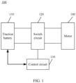
- FIG. 1 is a schematic diagram of a battery heating system 100 according to an embodiment of this application.
- the battery heating system 100 includes a traction battery 110, a switch circuit 120, and a control circuit 130.
- the control circuit 130 is connected to the switch circuit 140 to control the connection state of the switch circuit 140.
- the control circuit 130 can exchange information with the traction battery 110, and specifically, with a battery management system (battery management system, BMS) of the traction battery 110.
- BMS battery management system
- the switch circuit 120 is a switch circuit of a motor 140 or an inverter of the motor 140.
- the switch circuit 120 is disposed between the traction battery 110 and the motor 140.
- the switch circuit 120 is connected between the traction battery 110 and the motor 140, and the traction battery 110 supplies power to the motor 140 via the switch circuit 120, so as to drive the vehicle to run.
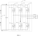
- the switch circuit 120 may include multiple legs and the multiple legs are connected to the traction battery 110 in parallel.
- the switch circuit 120 includes a leg 121, a leg 122, and a leg 123, and the leg 121, the leg 122, and the leg 123 are all connected to the traction battery 110 in parallel.
- each of the at least one leg used for forming the short-circuit loop includes a first switching device and a second switching device connected in series, and a joint between the first switching device and second switching device of each of the at least one leg is connected to at least one winding of the motor 140 in one-to-one correspondence.
- the number of the legs in the switch circuit 120 is equal to the number of the windings of the motor 140. It is assumed that the motor 140 includes three windings, the switch circuit 120 includes three legs, namely, the leg 121, the leg 122, and the leg 123. Each of the three legs includes an upper leg and a lower leg, and the upper leg and the lower leg are each provided with an IGBT switch.
- the motor 140 may specifically include a winding L1 connected to the leg 121, a winding L2 connected to the leg 122, and a winding L3 connected to the leg 123.
- One end of the winding L1 is connected to a joint between an upper leg 1211 and a lower leg 1212 of the leg 121
- one end of the winding L2 is connected to a joint between an upper leg 1221 and a lower leg 1222 of the leg 122
- one end of the winding L3 is connected to a joint between an upper leg 1231 and a lower leg 1232 of the leg 123.
- the other end of the winding L1, the other end of the winding L2, and the other end of the winding L3 are connected together.
- the motor 140 includes but is not limited to three windings, and may include six windings or the like.
- the switch module 120 may include six legs.
- Each leg in the switch circuit 120 can be implemented using various types of switches.
- each leg is implemented based on an insulated gate bipolar transistor (insulated gate bipolar transistor, IGBT) switch.
- IGBT insulated gate bipolar transistor
- control circuit 130 is configured to perform the method 200 shown in FIG. 3 .
- the method 200 includes some or all of the following steps.
- Step 210 Receive a heating signal sent by a BMS of a traction battery 110.
- Step 220 Control, according to the heating signal, at least one of multiple legs to form a short-circuit loop of the traction battery 110, the short-circuit loop being configured to discharge the traction battery 110 and heat the traction battery 110 during the discharging process.
- the formation of the short-circuit loop of the traction battery 110 allows the traction battery 110 to discharge via the short-circuit loop, thus heating the traction battery 110 during discharging of the traction battery 110. Because the short-circuit loop is formed by utilizing the switch circuit 120 of a motor 140, it is unnecessary to add an extra heating apparatus, and the traction battery 110 can be heated with low costs.
- the BMS can determine, based on state parameters of the traction battery 110, such as SOC, voltage U, temperature T, and other information, whether to send the heating signal to the control circuit 130.
- the control circuit 130 may be a controller of the motor 140 and is configured to control the operation of the motor 140 to drive the vehicle or the like and control the heating of the traction battery 110.
- the control circuit 130 may be a control circuit disposed independent of the controller of the motor 140 and is configured to control the heating process of the traction battery 110.
- the short-circuit loop of the traction battery 110 is the discharge loop of the traction battery 110.
- the positive and negative electrodes of the traction battery 110 are short-circuited.
- the traction battery 110 heats its internal resistor via the discharge loop, thus heating itself.
- the method 200 may include some or all of the following steps:
- control circuit 130 When the control circuit 130 performs steps 230 to 250, the control circuit is turned on based on a specified on duty cycle, such that the current I and voltage U in the short-circuit loop are controlled within a safety threshold, thus preventing the current of the traction battery 110 from exceeding its allowable discharge current, and/or preventing the voltage of the traction battery 10 from exceeding its minimum discharge voltage. This avoids damage to the traction battery 110 during heating and ensures the safety during the heating.
- the current I in the short-circuit loop that is, the discharge current I of the traction battery increases quickly.
- the current I exceeds the allowable discharge current I A of the traction battery 110 the traction battery 110 may be damaged, thus causing safety problems. In view of this, it is necessary to control the current I in the short-circuit loop not to exceed the allowable discharge current I A of the traction battery 110.
- the short-circuit loop In the case of controlling, based on a specified duty cycle, the short-circuit loop to turn on, the short-circuit loop is turned off before the current I in the short-circuit loop reaches the allowable discharge current I A , for example, the short-circuit loop is turned off when the current I exceeds a first threshold, and then the short-circuit loop is turned on again when the current I drops to a specified level. In this way, the current I can be controlled not to exceed the allowable discharge current I A of the traction battery 110 during battery heating until the traction battery 110 is heated to a pre-determined temperature.
- the first threshold is, for example, less than or equal to the allowable discharge current I A of the traction battery 110. Description is made below by using an example in which the first threshold is equal to the allowable discharge current I A .
- the duty cycle D can be determined based on the allowable discharge current I A , the voltage U, the internal resistance R, and the like of the traction battery 110.
- the duty cycle D max may be a constant value, that is, remains unchanged during heating; or may be adjusted in real time.
- the allowable discharge current I A of the traction battery 110 is related to the characteristics of the traction battery. If the allowable discharge current I A of the traction battery 110 is large, a large initial duty cycle D max may be set; otherwise, if the allowable discharge current I A of the traction battery 110 is small, a small initial duty cycle D max may be set.
- the voltage U of the traction battery 110 changes.
- the voltage U should not be smaller than the minimum discharge voltage U A of the traction battery 110. Therefore, when the voltage U is about to be lower than the minimum discharge voltage U A of the traction battery 110, for example, when the voltage is less than a second threshold, the duty cycle D can be reduced appropriately, so as to reduce the valid value of the current I, thus stabilizing the voltage U above the minimum discharge voltage U A .
- the second threshold is, for example, greater than or equal to the minimum discharge voltage U A of the traction battery 110. Description is made below by using an example in which the second threshold is equal to the minimum discharge voltage U A .
- step 230 performed by the control circuit 130 may further include: detecting the current I in the short-circuit loop via a current sensor disposed in the short-circuit loop; and/or determining the current I in the short-circuit loop based on the voltage U of the traction battery 110 and the internal resistance R of the traction battery 110.
- the current sensor can be disposed in the short-circuit loop to detect the current I more intuitively and accurately.
- a current sensor may be cascaded between the battery and the switch circuit 120.
- the current I in the short-circuit loop may be determined based on the voltage U of the traction battery 110 and the internal resistance R of the traction battery, which reduces the number of the devices in the short-circuit loop, thus reducing the costs and complexity.
- the control circuit 130 can obtain information of the traction battery 110 such as the voltage U, internal resistance R, or temperature T from the BMS of the traction battery 110.
- the internal resistance R of the traction battery 110 is the internal resistance R of the traction battery 110 under the current temperature T, and the internal resistance R can be determined according to a relationship curve between the internal resistance R and the temperature T.
- the change in temperature of the traction battery 110 causes a corresponding change in internal resistance R of the traction battery 110.
- the temperature T of the traction battery 110 increases, the internal resistance R of the traction battery 110 decreases, which leads to the increase of the current I.
- the temperature T and the internal resistance R satisfy a specified relationship curve.
- the temperature T of the traction battery 110 can be detected using a temperature sensor.
- step 250 performed by the control circuit 130 may further include: controlling, based on the on duty cycle, at least one leg in the switch circuit 120 to turn on.
- control circuit 130 can control the leg 121 in the switch circuit 120 to turn on, that is, control a switch V11 and a switch V12 on the leg 121 to be closed, thus forming the short-circuit loop including the traction battery 110, the switch V11, and the switch V12.
- control circuit 130 can control the leg 122 in the switch circuit 120 to turn on, that is, control a switch V21 and a switch V22 on the leg 122 to be closed, thus forming the short-circuit loop including the traction battery 110, the switch V21, and the switch V22.
- control circuit 130 can control the leg 123 in the switch circuit 120 to turn on, that is, control a switch V31 and a switch V32 on the leg 123 to be closed, thus forming the short-circuit loop including the traction battery 110, the switch V31, and the switch V32.
- the control circuit 130 can control the leg 121, the leg 122, and the leg 123 in the switch circuit 120 to turn on simultaneously, that is, control the switch V11, the switch V12, the switch V21, the switch V22, the switch V31, and the switch V32 to be closed, thus forming three short-circuit loops: a short-circuit loop including the traction battery 110, the switch V11, and the switch V12; a short-circuit loop including the traction battery 110, the switch V21, and the switch V22; and a short-circuit loop including the traction battery 110, the switch V31, and the switch V32.
- the short-circuit loop includes some or all legs of the motor 140, and the number of the legs included in the short-circuit loop may be determined depending on a heating requirement of the traction battery 110, such as a desired temperature or heating speed. For example, if the current temperature of the traction battery 110 is not quite low and the battery can operate normally with only a slight rise in temperature, some legs can be controlled to form a short-circuit loop, thus reducing the power output by the traction battery 110 for heating; and if the current battery temperature is quite low, all legs need to be controlled to form a short-circuit loop, thus improving the heating efficiency to raise the temperature of the traction battery 110 as soon as possible.
- a heating requirement of the traction battery 110 such as a desired temperature or heating speed.
- the short-circuit loop can be controlled to turn on or turn off more conveniently by controlling the on/off of the legs in the switch circuit 120 without adding extra devices, thus avoiding extra costs.
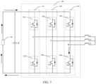
- a second switch 125 is disposed between the traction battery 110 and at least one leg in the switch circuit 120.
- step 250 performed by the control circuit 130 may further include: controlling, based on the on duty cycle, the second switch 125 to turn on.
- the second switch 125 may be, for example, a primary positive switch or primary negative switch in the entire vehicle system, and is connected to the positive terminal or negative terminal of the traction battery 110.
- the second switch 125 is the primary positive switch or primary negative switch in the entire vehicle system and located between the traction battery 110 and the switch circuit 120. It is assumed that three short-circuit loops need to be formed for heating the traction battery 110, the control circuit 130 only needs to control the second switch 125 to be closed. Similarly, when the three short-circuit loops need to be turned off, the control circuit 130 only needs to control the second switch 125 to turn off. In this way, it is unnecessary to simultaneously turn on or turn off the switch V11, the switch V12, the switch V21, the switch V22, the switch V31, and the switch V32 in the legs. Although the extra second switch 125 is added, the control circuit 130 can control the on/off of the short-circuit loop simply by controlling the on/off of the second switch 125 without controlling each leg in the switch circuit 120, thus reducing the complexity of the control circuit 130.
- the foregoing method 200 performed by the control circuit 130 may further include: obtaining an internal resistance R of the traction battery 110; determining an on frequency f of the short-circuit loop based on the internal resistance R of the traction battery 110; and controlling, based on the on frequency f , the short-circuit loop to turn on.
- a smaller internal resistance R of the traction battery 110 leads to a higher on frequency f .
- f 1/T.
- the valid value of the current I can be approximately: I ⁇ U 2 ⁇ L / D 2 , where 2 f L/D 2 can be defined as the equivalent external resistance during heating at a high frequency, that is, the boundary condition of a model for the traction battery 110 during heating at a high frequency.
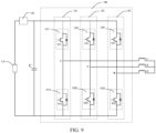
- the traction battery 110 is further connected to a capacitor branch 126 in parallel, the capacitor branch 126 includes a capacitor C and a first switch 124 connected in series, and the method further includes: before controlling the short-circuit loop to turn on, controlling the first switch 124 to turn off.
- the capacitor C typically provides voltage regulation and is configured to regulate voltage across two terminals of the traction battery 110, and therefore is also called a voltage regulator capacitor. When the short-circuit loop is formed, the capacitor C can share a part of the current I, thus reducing the heating efficiency.
- a first switch 124 is disposed at a branch where the capacitor C is located and controlled to turn off during heating, which can prevent the impact of the capacitor C on the traction battery 110 during heating, thus improving the heating efficiency.
- the capacitor C and the first switch 124 are connected in series.
- other connection relationships may be also present between the multiple capacitors and the first switch 124, for example, the position of the first switch 124 when a capacitor C1 and a capacitor C2 are connected in series or in parallel shown in FIGs. 11A and 11B .
- a smaller internal resistance R of the traction battery 110 leads to a faster increase of the current I in the short-circuit loop.
- the current I in the short-circuit loop can rapidly increase to more than 7000 A within 0.5 ms.
- a switching device needs to perform switching at a higher frequency, so as to control the turn-on/off time of the short-circuit loop, thus avoiding damage to the traction battery 110 during heating and ensuring the safety during the heating.
- the type of the traction battery 110 is not limited in the embodiments of this application.
- the traction battery 110 may be a solid-state battery or a traction battery with an internal resistance greater than a preset value.
- the preset value can be determined based on the tolerance level of the switching device, thus ensuring that the switching frequency of the switching device is within its tolerance range, avoiding a large current I in the short-circuit loop causing safety problems.
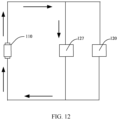
- An embodiment of this application further provides a heating manner.
- a third switch 127 is connected in parallel between two terminals of the traction battery 110. As shown in FIG. 12 , when the traction battery 110 is heated, the third switch 127 can be closed, thus forming a short-circuit loop including the traction battery 110 and the third switch 127.
- the method 200 performed by the control circuit 130 may further include: receiving a heating stop signal sent by the BMS of the traction battery 110; and controlling, according to the heating stop signal, the short-circuit loop to turn off, so as to stop heating the traction battery 110.
- FIG. 13 illustrates a possible specific implementation of the method 200. As shown in FIG. 13 , the method specifically includes some or all of the following steps.
- Step 301 Receive a heating signal sent by a BMS.
- Step 302 Control, according to the heating signal, at least one leg to form a short-circuit loop of a traction battery 110.
- Step 303 Determine whether a current I in the short-circuit loop exceeds an allowable discharge current IA of the traction battery 110, and/or a voltage U is less than a minimum discharge voltage U A .
- step 304 is performed; if I ⁇ I A and/or U > U A , step 305 is performed.
- Step 304 Control, based on an on duty cycle, the short-circuit loop to turn on or turn off.
- Step 305 Keep the short-circuit loop on.
- Step 306 Receive a heating stop signal sent by the BMS, and turn off the short-circuit loop according to the heating stop signal.
- step 303 needs to be performed periodically, that is, a relationship between currents I and I A and/or a relationship between voltages U and U A needs to be periodically determined, so as to ensure the safety during heating.
Landscapes
- Engineering & Computer Science (AREA)
- General Chemical & Material Sciences (AREA)
- Manufacturing & Machinery (AREA)
- Chemical & Material Sciences (AREA)
- Chemical Kinetics & Catalysis (AREA)
- Electrochemistry (AREA)
- Power Engineering (AREA)
- Microelectronics & Electronic Packaging (AREA)
- Physics & Mathematics (AREA)
- Electromagnetism (AREA)
- Automation & Control Theory (AREA)
- Secondary Cells (AREA)
- Electric Propulsion And Braking For Vehicles (AREA)
Applications Claiming Priority (1)
| Application Number | Priority Date | Filing Date | Title |
|---|---|---|---|
| PCT/CN2021/127572 WO2023070553A1 (fr) | 2021-10-29 | 2021-10-29 | Procédé de chauffage de batterie d'alimentation et système de chauffage |
Publications (2)
| Publication Number | Publication Date |
|---|---|
| EP4274002A1 true EP4274002A1 (fr) | 2023-11-08 |
| EP4274002A4 EP4274002A4 (fr) | 2025-02-26 |
Family
ID=86158885
Family Applications (1)
| Application Number | Title | Priority Date | Filing Date |
|---|---|---|---|
| EP21961908.7A Pending EP4274002A4 (fr) | 2021-10-29 | 2021-10-29 | Procédé de chauffage de batterie d'alimentation et système de chauffage |
Country Status (6)
| Country | Link |
|---|---|
| US (1) | US12431556B2 (fr) |
| EP (1) | EP4274002A4 (fr) |
| JP (1) | JP7684511B2 (fr) |
| KR (1) | KR102851091B1 (fr) |
| CN (1) | CN116368706B (fr) |
| WO (1) | WO2023070553A1 (fr) |
Families Citing this family (1)
| Publication number | Priority date | Publication date | Assignee | Title |
|---|---|---|---|---|
| CN115000585A (zh) * | 2022-06-23 | 2022-09-02 | 浙江极氪智能科技有限公司 | 电池振荡加热的控制电路、方法、系统及可读存储介质 |
Family Cites Families (13)
| Publication number | Priority date | Publication date | Assignee | Title |
|---|---|---|---|---|
| JP2004063397A (ja) * | 2002-07-31 | 2004-02-26 | Nissan Motor Co Ltd | 電池、組電池、および車両 |
| JP5741494B2 (ja) * | 2012-03-08 | 2015-07-01 | トヨタ自動車株式会社 | 電池及びその製造方法 |
| CN103419663B (zh) * | 2012-05-22 | 2015-11-25 | 比亚迪股份有限公司 | 电动汽车、电动汽车的动力系统及电池加热方法 |
| JP6160355B2 (ja) | 2013-08-12 | 2017-07-12 | 住友電気工業株式会社 | 蓄電池の自己発熱装置、蓄電池の自己発熱方法及び電源システム |
| CN108736107B (zh) * | 2018-05-22 | 2020-06-23 | 宁德时代新能源科技股份有限公司 | 加热模块和电池组加热方法、加热系统 |
| CN111347936B (zh) * | 2018-12-21 | 2022-07-15 | 比亚迪股份有限公司 | 一种车辆及其动力电池加热方法与装置 |
| CN112356738B (zh) | 2019-06-24 | 2022-04-22 | 宁德时代新能源科技股份有限公司 | 电机控制器、整车控制器、电池管理系统及控制方法 |
| CN110962692B (zh) * | 2019-06-24 | 2020-12-11 | 宁德时代新能源科技股份有限公司 | 电池组加热系统及其控制方法 |
| CN111048856B (zh) * | 2019-12-17 | 2021-06-01 | 北京理工大学 | 一种动力电池极速自加热方法和装置 |
| CN113131021B (zh) * | 2019-12-31 | 2023-08-08 | 比亚迪股份有限公司 | 一种电池加热方法、装置、设备及计算机可读存储介质 |
| CN113752908B (zh) * | 2020-06-04 | 2023-12-12 | 比亚迪股份有限公司 | 车辆、能量转换装置及其控制方法 |
| CN112731984B (zh) * | 2020-12-23 | 2022-02-22 | 恒大新能源汽车投资控股集团有限公司 | 动力电池温度调节方法、存储介质和系统 |
| CN113002366B (zh) * | 2021-04-30 | 2022-05-03 | 重庆长安新能源汽车科技有限公司 | 一种电动汽车及其动力电池加热系统和加热方法 |
-
2021
- 2021-10-29 WO PCT/CN2021/127572 patent/WO2023070553A1/fr not_active Ceased
- 2021-10-29 EP EP21961908.7A patent/EP4274002A4/fr active Pending
- 2021-10-29 CN CN202180055390.0A patent/CN116368706B/zh active Active
- 2021-10-29 KR KR1020247000967A patent/KR102851091B1/ko active Active
- 2021-10-29 JP JP2024501899A patent/JP7684511B2/ja active Active
-
2023
- 2023-08-21 US US18/453,056 patent/US12431556B2/en active Active
Also Published As
| Publication number | Publication date |
|---|---|
| JP7684511B2 (ja) | 2025-05-27 |
| JP2024525756A (ja) | 2024-07-12 |
| CN116368706B (zh) | 2026-03-27 |
| KR20240019333A (ko) | 2024-02-14 |
| EP4274002A4 (fr) | 2025-02-26 |
| KR102851091B1 (ko) | 2025-08-26 |
| US12431556B2 (en) | 2025-09-30 |
| WO2023070553A1 (fr) | 2023-05-04 |
| CN116368706A (zh) | 2023-06-30 |
| US20230395899A1 (en) | 2023-12-07 |
Similar Documents
| Publication | Publication Date | Title |
|---|---|---|
| US12117499B2 (en) | Battery management apparatus, battery management method, and battery energy storage system | |
| JP3706565B2 (ja) | ハイブリッドカー用の電源装置 | |
| KR102392376B1 (ko) | 배터리 시스템 | |
| EP4369475A1 (fr) | Procédé de chauffage de batterie, appareil de charge et système de gestion de batterie | |
| EP1670113A2 (fr) | Système de contrôle d'égalisation de tension pour un accumulateur | |
| US12113388B2 (en) | Charging control method and apparatus, battery management system and readable storage medium | |
| US12494525B2 (en) | Lithium battery system and overhead working truck | |
| US20240250320A1 (en) | Discharge method and discharge apparatus for battery | |
| KR20220110665A (ko) | 충전 방법 및 전력 변환 장치 | |
| US20240178473A1 (en) | Battery heating apparatus and control method thereof, control circuit and power plant | |
| US12431556B2 (en) | Heating method and heating system of traction battery | |
| US20240235243A1 (en) | Power battery voltage regulation system and control method and control apparatus thereof | |
| US20230378799A1 (en) | Charge method and charge apparatus for battery | |
| CN113060048A (zh) | 一种动力电池脉冲加热系统及其控制方法 | |
| US11933855B2 (en) | Apparatus for measuring impedance of fuel cell for vehicle and method thereof | |
| US20230299374A1 (en) | Battery heating apparatus, control method and control circuit thereof, and motive apparatus | |
| JPH11113183A (ja) | バッテリ装置 | |
| JP7741304B2 (ja) | 電池制御装置 | |
| US20240030723A1 (en) | Equalization device | |
| US20200350771A1 (en) | Method for generating data diagram and method for managing battery pack | |
| US11971768B2 (en) | Power supply control device, power supply device, and power supply control method | |
| US20230411734A1 (en) | Battery heating device and control method and circuit therefor, and power device | |
| JP2001161037A (ja) | 電気自動車を駆動する電池群の充放電制御方法 | |
| CN224036455U (zh) | 一种电池加热电路、电池热管理系统及车辆 | |
| EP4568059A1 (fr) | Procédé et système d'équilibrage de cellules et batteries secondaires les comprenant |
Legal Events
| Date | Code | Title | Description |
|---|---|---|---|
| STAA | Information on the status of an ep patent application or granted ep patent |
Free format text: STATUS: THE INTERNATIONAL PUBLICATION HAS BEEN MADE |
|
| PUAI | Public reference made under article 153(3) epc to a published international application that has entered the european phase |
Free format text: ORIGINAL CODE: 0009012 |
|
| STAA | Information on the status of an ep patent application or granted ep patent |
Free format text: STATUS: REQUEST FOR EXAMINATION WAS MADE |
|
| 17P | Request for examination filed |
Effective date: 20230804 |
|
| AK | Designated contracting states |
Kind code of ref document: A1 Designated state(s): AL AT BE BG CH CY CZ DE DK EE ES FI FR GB GR HR HU IE IS IT LI LT LU LV MC MK MT NL NO PL PT RO RS SE SI SK SM TR |
|
| RAP1 | Party data changed (applicant data changed or rights of an application transferred) |
Owner name: CONTEMPORARY AMPEREX TECHNOLOGY(HONG KONG) LIMITED |
|
| DAV | Request for validation of the european patent (deleted) | ||
| DAX | Request for extension of the european patent (deleted) | ||
| A4 | Supplementary search report drawn up and despatched |
Effective date: 20250124 |
|
| RIC1 | Information provided on ipc code assigned before grant |
Ipc: H01M 10/48 20060101ALI20250120BHEP Ipc: H01M 10/44 20060101ALI20250120BHEP Ipc: H01M 10/42 20060101ALI20250120BHEP Ipc: H01M 10/637 20140101ALI20250120BHEP Ipc: H01M 10/625 20140101ALI20250120BHEP Ipc: H02J 7/00 20060101ALI20250120BHEP Ipc: H01M 10/615 20140101AFI20250120BHEP |