EP4274723B1 - Procédé et système mis en oeuvre par ordinateur permettant de déterminer au moins une machine - Google Patents
Procédé et système mis en oeuvre par ordinateur permettant de déterminer au moins une machine Download PDFInfo
- Publication number
- EP4274723B1 EP4274723B1 EP23710007.8A EP23710007A EP4274723B1 EP 4274723 B1 EP4274723 B1 EP 4274723B1 EP 23710007 A EP23710007 A EP 23710007A EP 4274723 B1 EP4274723 B1 EP 4274723B1
- Authority
- EP
- European Patent Office
- Prior art keywords
- machine
- data
- component
- unit
- simulation
- Prior art date
- Legal status (The legal status is an assumption and is not a legal conclusion. Google has not performed a legal analysis and makes no representation as to the accuracy of the status listed.)
- Active
Links
Images
Classifications
-
- B—PERFORMING OPERATIONS; TRANSPORTING
- B29—WORKING OF PLASTICS; WORKING OF SUBSTANCES IN A PLASTIC STATE IN GENERAL
- B29C—SHAPING OR JOINING OF PLASTICS; SHAPING OF MATERIAL IN A PLASTIC STATE, NOT OTHERWISE PROVIDED FOR; AFTER-TREATMENT OF THE SHAPED PRODUCTS, e.g. REPAIRING
- B29C45/00—Injection moulding, i.e. forcing the required volume of moulding material through a nozzle into a closed mould; Apparatus therefor
- B29C45/17—Component parts, details or accessories; Auxiliary operations
- B29C45/76—Measuring, controlling or regulating
- B29C45/766—Measuring, controlling or regulating the setting or resetting of moulding conditions, e.g. before starting a cycle
-
- G—PHYSICS
- G06—COMPUTING OR CALCULATING; COUNTING
- G06F—ELECTRIC DIGITAL DATA PROCESSING
- G06F30/00—Computer-aided design [CAD]
- G06F30/20—Design optimisation, verification or simulation
-
- B—PERFORMING OPERATIONS; TRANSPORTING
- B29—WORKING OF PLASTICS; WORKING OF SUBSTANCES IN A PLASTIC STATE IN GENERAL
- B29C—SHAPING OR JOINING OF PLASTICS; SHAPING OF MATERIAL IN A PLASTIC STATE, NOT OTHERWISE PROVIDED FOR; AFTER-TREATMENT OF THE SHAPED PRODUCTS, e.g. REPAIRING
- B29C45/00—Injection moulding, i.e. forcing the required volume of moulding material through a nozzle into a closed mould; Apparatus therefor
- B29C45/17—Component parts, details or accessories; Auxiliary operations
- B29C45/76—Measuring, controlling or regulating
-
- G—PHYSICS
- G05—CONTROLLING; REGULATING
- G05B—CONTROL OR REGULATING SYSTEMS IN GENERAL; FUNCTIONAL ELEMENTS OF SUCH SYSTEMS; MONITORING OR TESTING ARRANGEMENTS FOR SUCH SYSTEMS OR ELEMENTS
- G05B19/00—Program-control systems
- G05B19/02—Program-control systems electric
- G05B19/418—Total factory control, i.e. centrally controlling a plurality of machines, e.g. direct or distributed numerical control [DNC], flexible manufacturing systems [FMS], integrated manufacturing systems [IMS] or computer integrated manufacturing [CIM]
- G05B19/41885—Total factory control, i.e. centrally controlling a plurality of machines, e.g. direct or distributed numerical control [DNC], flexible manufacturing systems [FMS], integrated manufacturing systems [IMS] or computer integrated manufacturing [CIM] characterised by modeling, simulation of the manufacturing system
-
- G—PHYSICS
- G06—COMPUTING OR CALCULATING; COUNTING
- G06F—ELECTRIC DIGITAL DATA PROCESSING
- G06F2113/00—Details relating to the application field
- G06F2113/10—Additive manufacturing, e.g. three-dimensional [3D] printing
Definitions
- the invention relates to a method or a system for determining at least one machine for processing plastics and other plasticizable materials on the basis of criteria determined and/or determinable for the production of components with the features of claim 1 or 10, as well as an associated machine control for carrying out the method with the features of claim 17 and a computer program product for carrying out the method with the features of claim 18.
- component is used in this application, this is not intended to be restrictive, because the process can also be used in multi-component injection molding, multi-cavity injection molding, injection molding with so-called family tools or known special processes or also in additive manufacturing. In all of these cases, components, items and objects are produced for which the term “component” is used synonymously.
- process parameters or "machine parameters” are the parameters required for the manufacture of components on plastics processing machines with which such machines manufacture components.
- these parameters are not only, but in particular, pressure, path of a conveying means such as a conveyor screw, effective screw length, calculated stroke volume, shot weight, material throughput, injection pressure, holding pressure time, injection flow, temperature, injection speed, screw peripheral speed, screw torque, nozzle contact force, heating power, heating zones, filling volume, discharge volume, mass volume, drop size, drop volume, opening and closing force of a mold clamping unit, mold installation height, plate spacing of the mold carriers, clear column spacing, dimensions of the mold clamping surface, weight of the movable mold carrier, ejector force, ejector path, dry run time, machine performance, energy consumption, design and the like.
- machine unit refers to parts and components of a machine for processing plastics and other plasticizable materials. These machine units can be manufactured in a modular manner as independent assemblies and fed into a machine. In the example of a plastic injection molding machine, machine units can be a plasticizing cylinder, a screw shaft, drive units, a mold closing unit or an injection molding unit or the like. Similar machine units are basically interchangeable and can therefore be optimized in relation to other machine units with regard to the component to be manufactured.
- this application refers to a "reference database”
- This reference machine data establishes a reference in particular to machines that already exist or are still to be manufactured, as well as their machine parameters.
- the reference machine data also includes the data that enables the machine manufacturer to manufacture a new machine.
- Reference part data sets created from the reference data in the reference database allow specific data sets to be assigned to machine parameters and process parameters, for example to enable certain speeds or pressures in the example of an injection molding machine when injecting into a mold cavity or to specify the installation space conditions or the discharge conditions in a machine for the additive manufacturing of components.
- user data refers to data that allows a user to provide the process or system with enough information to enable a configuration of a suitable machine to be developed.
- This data includes in particular information about the component to be manufactured, for example in the form of CAD data, preferably three-dimensional, or about a shape or cavity of such a component.
- user data also includes information about the material to be processed or the corresponding material class, information about the machine or target machine data or about the process, such as target process data.
- User data can also include user preferences.
- user preference is used when the user can enter information relating to, for example, the production time, the energy requirement per component, the costs per component or the like. These preferences should preferably be fulfilled, but can also be weighted or set aside by the user if necessary. In contrast, this is not the case with information about the component and/or a cavity, for example.
- expert knowledge refers to the knowledge that is available to an experienced operator of such a machine. This can be present or liquid knowledge, but expert knowledge also includes non-liquid knowledge that is accessible, for example, from specialist literature. This knowledge is based in particular on knowledge of the sequences and relationships of the components involved in the processes running on these machines and their interaction with one another. This expert knowledge also includes, for example, knowledge of the respective machines and their machine data or their structure, as well as knowledge of materials and their properties. The expert knowledge enables a trained user to put such a machine into operation at least to the extent that a component can be manufactured and the machine is operational. Expert knowledge also includes everything that is required to manufacture high-quality components.
- a method and a device for simulating a control and/or machine behavior of machine tools or production machines are known, wherein data about the machine tools or production machines are transmitted from these to a simulation device via an intranet and/or via the Internet.
- parameter data and/or configuration data and/or hardware data and/or program data and/or performance data are transmitted as data.
- the simulation device stores data from several machine tools or production machines, wherein in particular simulation results of at least two machine tools or production machines are automatically compared with one another.
- the simulation device processes simulation results in such a way that after the simulation of at least two machines, a machine tool or production machine is suggested for use.
- a method for configuring a robot-supported processing system is known in which a processing system is configured based on a task-related processing plan with several processing aspects.
- the processing plan is transmitted to a network-based configurator and broken down into several aspects.
- a necessary configuration module is selected and the operating system required for the module is loaded from a cloud and saved in the respective configuration module.
- the configuration plan created in this way is transmitted to the processing system. All configuration modules in the operating system are coupled in a central control system ready for operation and the configured processing system is put into operation.
- An intelligent molding system that utilizes data directly associated with a molding environment or a specific mold.
- the accessible data typically stored locally in a storage device in the mold or entered via an HMI, identifies parameters important to mold setup and machine operation.
- a machine controller configures a molding machine to an initial setting defined by the data and considered to be close to an optimal operating condition for the mold.
- the Tool setup data may include information on a fill profile for a molded article divided into different zones with different thicknesses and geometries. Weighting factors for the different zones compensate for the different cooling and flow properties.
- the memory may also be used to store historical data on tool operation, settings and alarms. The transfer of process parameters from a test bench to a machine is described, but the suitability of the machine is not estimated or evaluated.
- the US 2001/0051858 A1 describes a method for setting parameters in an injection molding machine using data from a filling simulation to create a database with a relationship between the machine-side parameters and the product quality of the injection molded part.
- the created database can then be used in a neural network.
- a method for determining and displaying process parameter values of an injection molding process in an injection molding tool is known.
- geometry data for the injection molding tool and/or a molded part to be produced in the injection molding tool is determined.
- An injection molding process is then carried out with the injection molding tool and measured values are recorded as a function of an injection time and/or an actuator position.
- a flow front position within the injection molding tool or the molded part and optionally a flow front speed are determined as process parameter values on the basis of the measured values and the geometry data.
- further process parameter values can be determined as a function of the injection time and/or the actuator position and/or the flow front position.
- At least some of the determined process parameter values are displayed on a display device as a function of the injection time and/or the actuator position and/or the flow front position. The information obtained in this way is not used further.
- WO 2014/183863 A1 A method for operating an injection molding machine for processing plastics, with a mold closing unit for opening and closing an injection mold with at least one mold cavity for producing an injection molded part, with an injection molding unit for plasticizing and injecting the plasticizable material into the mold cavity, and with a control system for operating the injection molding machine.
- the control system contains expert knowledge about the operation of the injection molding machine and its possible existing peripheral devices and the production of injection molded parts in injection molding technology in order to produce an injection molded part using injection molding parameters, with interactive contact with an operator if necessary.
- the system and process parameters required for the production of the injection molded part can be calculated by the control system, ie the machine adjusts itself to an optimal parameterization with a known machine.
- the US 2002/0188375 A1 discloses a method in which the molding conditions of an injection molding machine are determined by performing virtual molding using CAE (computer aided engineering).
- CAE computer aided engineering
- the actual molding is performed under preliminary molding conditions to obtain an actual profile showing the change in load pressure actually measured during at least one injection step of the actual molding.
- virtual injection molding is performed using CAE using the preliminary molding conditions to obtain a virtual profile showing the change in load pressure simulated during at least one injection step of the virtual injection molding.
- the preliminary molding conditions are changed by CAE so that the virtual profile matches the actual profile to obtain intermediate molding conditions.
- the intermediate molding conditions are optimized to obtain real molding conditions for the injection molding machine. This achieves an adaptation and thus improvement of virtual data within the framework of a real production process.
- From the EP 1 302 823 B1 is a method for the computer-aided planning of a plant in the basic materials industry, in particular a metallurgical facility, with the provision of plant data in a data structure and the input of user-specific data and/or specifications via a user interface by an authorized user.
- the plant is configured by linking user-specific data and/or specifications with plant data available in the data structure using models describing the plants and/or the processes used.
- the result is an output of a configured product in the form of a structured configuration suggestion.
- the method describes a configuration of a plant based on target data to be entered, but without selection based on simulated tool or product data.
- the DE 10 2020 107 524 A1 discloses an injection molding analysis method for generating an analysis condition of an injection molding machine using at least one computer, wherein the at least one computer carries out the following steps: selecting an injection molding machine, wherein the injection molding machines are each assigned a predetermined correction amount for the injection molding, generating a second analysis condition for the selected injection molding machine on the basis of an obtained first analysis condition and the predetermined correction amount of the selected injection molding machine and outputting the generated second analysis condition.
- the method thus describes the generation of a correction factor on the basis of which a selected injection molding machine can be operated.
- the US 2005/0114104 A1 relates to a method and apparatus for analyzing fluid flow taking into account heat transfer effects and in particular a phase change from a molten state to a solid state.
- the method and apparatus can be applied to the analysis of an injection molding process for producing a molded polymer component from a polymer.
- the method can be used to determine the pressure required to fill a mold cavity and pressure gradients introduced during filling of the cavity of an injection mold.
- the results of these analyses can be used to determine the number and position of gates, to determine the best material for the component, and to optimize the process conditions used in the molding process.
- the DE 10 2013 008 245 A1 serves to operate an injection molding machine for processing plastics, which has a mold closing unit with at least one mold cavity, an injection molding unit and a control system for operating the injection molding machine.
- Expert knowledge about the operation of the injection molding machine and any peripheral devices it may have, as well as about the production of molded parts using injection molding technology, is stored in the control system in order to produce a molded part using injection molding parameters, with interactive contact with an operator if necessary.
- the parameters required for producing the molded part can be calculated by the control system, so that a user-friendly setup of a machine for processing plastics is provided.
- the US 2002/0193972 A1 discloses a workshop setup/design and operation method for simulating a virtual workshop, which is a data model of an at least partially reorganized workshop.
- the virtual workshop performs a quasi-production activity carried out to verify a production state and a physical transportation state of the manufactured product.
- a real workshop is built that matches the verified virtual workshop.
- the built actual workshop is remotely monitored and a result of this monitoring is compared with a result of a verification during a virtual workshop verification process. In this way, the verification of the entire workshop can be carried out so that workshop operations such as new setup and modification of a workshop can be carried out efficiently and quickly in a short period of time.
- a computer is given an application program that describes the machining of a workpiece using a machine tool in instruction steps.
- the computer uses a simulation program for controlling the machine tool to execute the application program and determines machine-dependent control commands for the machine tool step by step. It uses an internal model of the machine tool and the determined machine-dependent control commands to determine the expected actual states of the machine tool and thus simulates the execution of the machine-dependent control commands.
- the simulation program is designed as control software. It determines the machine-dependent control commands depending on a virtual time base that is independent of real time.
- the US 2017/0308057 A1 relates to a computer-implemented method for part analysis, in particular for analyzing the quality of the machining process and preferably the design process of a workpiece that is machined by at least one CNC machine.
- the method can comprise providing a digital machine model of the CNC machine with real-time and non-real-time process data of the at least one CNC machine, wherein the real-time and non-real-time process data are recorded during the machining process of the CNC machine.
- the machining process is then simulated using the digital machine model based at least partially on the recorded real-time and non-real-time process data.
- the present invention is based on the object of providing a user with at least one machine for his application that is best suited for it under the given circumstances.
- the computer-implemented method is used to determine which machine is preferably best suited for producing a component to be manufactured for at least one machine for processing plastics and other plasticizable materials. This determination is made on the basis of criteria determined and/or determinable for producing the at least one component.
- a reference database with reference machine data is provided, which in particular includes reference part data sets required for determining machine parameters, with machine parameters being assigned to each reference part data set.
- user data is provided as specific and/or determinable criteria via a user interface in a data storage device, which user data includes data required for the manufacture of the at least one component, in particular CAD data.
- the user data also includes at least one group of data comprising at least material characteristics, target machine characteristics and/or target process data.
- a simulation for producing the at least one component on a machine is carried out by generating simulation data sets. Additionally or alternatively, a simulation data set that was already generated during or for the production of at least one component on the machine can also be used. These simulation data sets are then segmented to extract partial data sets in order to achieve the assignment to the machine-side parameters with which a machine is to be operated to produce the at least one component.
- the partial data sets determined in this way are compared with the reference partial data sets in the reference database for partial matches, in particular in order to obtain process parameters and machine parameters that allow for a more precise definition of how a suitable machine or machine unit is to be configured or constructed. Based on the partial matches, this leads to the output of a minimum requirement for a machine or machine unit suitable for the manufacture of at least one component.
- At least two of the elements - which can also include other elements - are collected from different machines, including the user data, the simulation data sets, the partial data sets and the minimum requirements.
- Clusters are formed from these, grouped according to the same or similar machine configurations, the same processes and/or the same or similar materials to be processed, and these clusters are evaluated in order to operate machines with a minimum requirement adjusted as a result of the results of the evaluation using federated learning.
- federated learning i.e. in the sense of "swarm intelligence” or "swarm knowledge”.
- the method is therefore suitable for being carried out on several machines and thus for forming and evaluating clusters, especially with the same machine configurations, the same processes and/or the same materials to be processed.
- the increased amount of data obtained in this way can sharpen the results in the results database even further.
- the minimum requirement can now be compared with the available machines or machine units. This comparison leads to the determination of at least one, preferably several machines or machine units, possibly prioritized according to certain criteria, that are suitable for producing the at least one component. This machine or machine unit is then operated to produce the at least one component.
- a suitable machine or machine unit is determined either by selecting it from a machine portfolio of an operator's machine park, whereby the machines or machine units can also be located at different locations, and/or, if a suitable machine is available from at least one supplier on the market, possibly by proposing that the component to be manufactured be manufactured on a suitable machine from at least one supplier.
- the latter case particularly concerns awarding the manufacturing to a contract manufacturer who currently has the suitable machine in operation.
- a suitable machine can also be configured by the manufacturer and then manufactured. This is particularly the case if, even after weighing up and weighting the criteria accordingly, it is concluded that the component to be manufactured cannot be manufactured on the existing machines or those available to the respective user. In this case, manufacturing a machine that is specially suited to the component is an advantageous alternative.
- a suitable machine or machine unit it is determined globally or regionally where suitable machine units are located in order to then set up a machine to manufacture the component. It is conceivable that it makes more sense to search for suitable machine units on the market worldwide, especially when rapid production of components is required. It may be necessary for a machine in Asia - which in the example is an injection molding machine - to have a large mold clamping unit and a large plasticizing unit - a smaller plasticizing unit for the component to be manufactured now can only be supplied by the manufacturer with a corresponding delivery time. However, on the global market, a suitable plasticizing unit can possibly be found in North America that can be delivered to Asia at short notice in order to quickly convert the machine there and thus be able to manufacture the component.
- the user data can also include user preferences that can be set linearly or discretely using a controller unit based on a defined parameter set. This allows a change in the minimum requirement to be analyzed and output based on the user preferences.
- the user can thus advantageously weight the machine-side or process-side user data on the one hand, but can also introduce additional user preferences that particularly affect "soft" factors such as the cost per component, the speed per component or the energy costs per component or the like. This information is therefore advantageously included in the selection of a suitable machine. This means that components can be manufactured on a machine more quickly and with lower energy costs.
- the existing user data is only partially used.
- these can be segmented again in addition to or separately to extract partial data sets.
- These partial data sets are also assigned to machine parameters in order to advantageously optimize the selection of the suitable machine.
- the method is preferably applied to an injection molding machine or to a machine for the additive manufacturing of components. It is advantageous if corresponding simulation results are available for such machines to such an extent that such results can be accessed without additional costs and represent the starting point for determining the appropriate machine.
- the simulation used for producing the at least one component is a filling simulation for filling a mold cavity of an injection molding tool/tool unit or a simulation of a component structure in an additive manufacturing and/or a Flow simulation of a plasticizing process of the plasticizable material in a plasticizing unit.
- Such simulations are already widely used in the engineering of molds and in additive manufacturing for the design of injection molds and molds. They can be used to convert a specific "manufacturing scenario" or "injection molding scenario” into a suitable tool unit or injection molding tool.
- These simulation results are therefore the starting point for combining (injection molding) tool-side or component-side simulation results with the design of, for example, the plasticizing screw and machine. All of this with the aim of advantageously finding the machine or machine unit that is best suited to the production of the respective component.
- the machine selection can thus be optimized based on the (injection molding) tool or the component to be manufactured.
- injection molding injection molding
- the simulation results of the mold making are advantageously transferred into the selection process for a suitable injection molding machine.
- a self-learning system is assigned to the reference database so that information for suitable machines or machine units in conjunction with associated user data is advantageously made available to the reference database for future evaluations and assessments.
- the results of the evaluation of a federated learning can be used at least partially with each other, preferably cloud-based, to determine comparison results.
- the operator of such plants can roll out an algorithm generated in this way from his "model factory” to other production sites and receive the same good machine selection options everywhere while protecting know-how.
- the algorithms generated in this way can also be made available to the machine manufacturer, at least in part, so that the models provided by the manufacturer and the expert knowledge can be further refined with such information.
- the system has a reference database with reference machine data that can be assigned to reference partial data sets for determining machine parameters; a user interface that is set up to provide the user data explained above in a data store; a simulation unit that is set up to simulate the production of the at least one component on a machine by generating simulation data sets on the basis of the user data and/or a reading unit that is set up to read in existing simulation data sets generated on or for a machine; a segmentation unit that is set up to segment the simulation data sets for the extraction of partial data sets to the extent explained above; a first pattern comparison unit that is set up to compare the partial data sets with the reference data sets for partial matches; an analysis unit that is set up to determine a minimum requirement for a machine or machine unit when producing at least one component
- the system thus advantageously allows an inexperienced user to be provided with a user- and machine-oriented and, if necessary, optimized selection option for suitable machines or machine units based on the component and/or its shape or a cavity in which the component is to be manufactured.
- a suitable machine can advantageously be available in the company's own machine park or from a contract manufacturer on the market or it can preferably turn out that a suitable Machine or machine unit is to be configured or manufactured by the manufacturer. This creates the conditions for selecting a machine with its technical environment and technical requirements that is equipped in such a way that the component to be manufactured can be manufactured in the best possible way, or at least as well as possible, on the machine suitable for this purpose.
- a global or regional search system is provided which is set up to determine, after determining a suitable machine or machine unit, globally or regionally, e.g. within a predetermined radius, where suitable machines or machine units are located in order to set up a machine for producing the at least one component.
- This can advantageously allow a machine to be set up more quickly if it can be determined globally or regionally where in the world suitable machine units are to be procured in order to then, if necessary, convert a machine that is not yet fully suitable or set up a suitable machine on site.
- user preferences can be entered via a user interface. These user preferences can be set linearly or discretely using a control unit based on a defined set of parameters. In other words, it is possible to weight the user preferences and thus both the user data and soft factors, which advantageously enable faster and energy-optimized production of the component, for example. The user preferences are then incorporated into the minimum requirements for the suitable machine.
- the segmentation unit is set up to segment not only the simulation data sets and the associated user data, but also the user data in addition to or separately from the extraction of partial data sets.
- This can advantageously be used to obtain additional information that influences the machine parameters that determine the selection of the appropriate machine. This applies in particular and especially to user preferences.
- additional information can be obtained in addition to or separately from the extraction of partial data sets that influences the machine parameters that in turn determine the selection of the appropriate machine.
- the system is intended for use on an injection molding machine or on a machine for additive manufacturing of components.
- These machines in particular have proven tools that can provide simulation data sets.
- These Simulation data sets can advantageously be translated into real machine parameters using the framework conditions underlying the user data.
- suitable and proven simulations are a filling simulation for filling a mold cavity of an (injection molding) tool or a tool unit or a simulation of a component structure in additive manufacturing and/or a flow simulation of a plasticizing process of the plasticizable material in a plasticizing unit.
- the reference database is assigned a self-learning system that is advantageously suited to segmenting and grouping results that have already been determined in order to make them accessible for future applications.
- the above object is also achieved by a machine control for a machine for processing plastics and other plasticizable materials, which is set up, designed and/or constructed to carry out the process.
- the problem is also solved by a corresponding computer program product with a program code that is stored on a computer-readable medium and is suitable for carrying out the method.
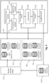
- Fig. 2 shows a computer-implemented system for carrying out a computer-implemented method for determining at least one machine 1.1 for processing plastics and other plasticizable materials on the basis of criteria determined and/or determinable for the production of components.
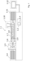
- the machine is preferably an injection molding machine for processing plastics and other plasticizable materials, as described in Fig. 1 shown, or a machine for the additive manufacturing of components. In principle, it can be used on other plastic processing machines.
- plasticizable materials is to be understood in a broad sense and includes in particular, but not exclusively, the plastics mentioned, e.g. ceramic, metallic and/or powdery masses as well as paper, cellulose, starch, cork, etc. as well as mixed materials between such plasticizable materials or recycled materials. In principle, the process can also be used for previously plasticized materials or plastic masses that harden automatically or with the use of aids after application.
- Fig. 2 shows the system for determining at least one machine 1.1 in the manner of a configurator 2.5 as well as the method for determining a preferably component and user-optimized configuration of a machine or machine units of a machine, in the embodiment of a plastic injection molding machine according to Fig. 1
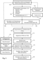
- the concrete procedure is shown in the flow chart of the Fig. 3 shown.
- the system is described below in an example using an injection molding machine for processing plasticizable materials according to Fig. 1 explained.
- the system and the process can also be used on a machine for additive manufacturing of components 2.14 as well as generally to or on machines in the plastics processing industry.
- user data 2.3 such as target machine data of the injection molding machine, CAD data of the component to be manufactured 2.14 and target process parameters according to Fig. 2 initially stored in a data store 2.2.
- Expert knowledge 130 and/or existing results, e.g. from earlier procedures of the present procedure, from a results database 2.13 can also be included in the data store 2.2.
- the configurator 2.5 then generates the results database 2.13 with component- and user-specific configurations of machine units of machines or machines 1.1, in the embodiment example injection molding machines, from the recorded user data 2.3 and reference machine data 2.4, whereby the configurations are preferably sorted in the results database 2.13 according to a requirement profile or minimum requirements MA.
- plasticizable material is introduced into a temperature-controlled plasticizing unit 1.7 via a material feed unit 1.10, plasticized by a screw shaft 1.8 with a non-return valve 1.9 and then introduced into at least one cavity of the tool unit 1.5, here an injection molding tool, via the material outlet unit 1.6.
- at least one machine control 1.2 with a data memory 1.3 is provided in the machine 1.1, wherein the machine control 1.2 can be operated by a display device 1.12.
- a component-specific injection molding machine is required, i.e. a machine 1.1 that meets the requirements for manufacturing component 2.14 and is suitable for this production, so that a component with properties that meet the quality requirements can be manufactured.
- the number of cavities and the geometry of the cavities of the tool unit 1.5 must be coordinated with the drive units 1.4, 1.11 (e.g. required closing force, required injection force), with the plasticizing unit 1.7 (e.g. screw geometry) and with the material feed unit 1.10 or the material outlet unit 1.6.
- the configurator 2.5 provides automatically provides a component- and user-optimized configuration of a machine 1.1 via a user interface 2.1, e.g. from CAD data of the component to be manufactured 2.14 and other user data 2.3.
- CAE simulations of the component-specific injection molding process are carried out in a simulation unit 2.7 and the simulation results (simulation data SD) are used to select suitable configurations.
- the simulation unit can basically be provided on any suitable computer, but it can also run on a machine control 1.2.
- the injection molding process or the manufacturing process in general can be simulated using a CAE simulation in the simulation unit 2.7.
- a CAE simulation usually consists of a flow simulation of the plasticized material in the mold of the tool unit 1.5 (filling simulation) and/or a flow simulation of the plasticizing process (melting simulation) in the plasticizing unit 1.7.
- a filling simulation is usually replaced by a simulation of a component structure.
- the CAD data of the component to be manufactured and/or other user data 2.3 such as process data, such as material properties, are used in the CAE simulation to determine component- and machine-specific target curves of the process parameters, such as injection pressure, holding pressure, speed of the drive units, filling volume, etc. (see above).
- the user data 2.3 including e.g. CAD data of the component to be manufactured 2.14, target machine characteristics and target process data, are entered via a user interface 2.1 and stored in a data storage device 2.2.
- a data acquisition unit 2.6 transfers the user data 2.3 to the configurator 2.5 and transfers the CAE simulation requires user data 2.3 into the simulation unit 2.7, which then passes the simulation data SD on to the segmentation unit 2.8.
- the remaining user data 2.3 in particular those, but not only those, which are not processed in the simulation unit 2.7, can be introduced directly into the segmentation unit 2.8 and divided together with the simulation data SD into partial data sets TDS.
- a working data set is now generated for a configuration of a machine 1.1 or machine unit that (if possible) best satisfies the requirements for high-quality production of at least one component 2.14 that can be identified and determined on the basis of the simulation and the user data.
- the work data set is compared with the reference machine data 2.4 in a first pattern comparison unit 2.9, with at least one criterion from the machine characteristics or from the target process parameters or from the material characteristics being used for comparison.
- comparison data is created in the pattern comparison unit 2.9.
- a requirement profile is created in an analysis unit 2.10 or a profile creation unit as a minimum requirement MA for the machine 1.1 or machine unit to be configured, which is compared in a second comparison unit 2.11 with the stored machines 1.1 and machine units from the reference machine data 2.4.
- the second pattern comparison unit 2.11 at least one component and user-optimized machine 1.1, preferably several machines, or at least one component and user-specific configuration of machine units is selected that best meets the minimum requirement MA.
- the second pattern comparison unit 2.11 is preferably set up to collect at least two of the elements - but possibly also other elements - comprising the user data 2.3, the simulation data sets SD, the partial data sets TDS and the minimum requirements MA from different machines and to form clusters therefrom, grouped according to the same or similar machine configurations, the same processes and/or the same or similar materials to be processed, and to evaluate these clusters in order to operate machines with a minimum requirement MA adapted as a result of the results of the evaluation by means of federated learning.
- the selected machines are then sorted in an output unit 2.12 according to at least one criterion from the user data 2.3, transferred to a results database 2.13 and made available via the user interface 2.1.
- a code e.g. DataMatrix code
- DataMatrix code can be provided for the result obtained in addition to the database entry, with which the result can be called up again at any time (with all selected/simulated data).
- Fig. 3 shows a flow chart for a computer-implemented method for determining at least one machine suitable for the production of at least one component for processing plastics and other plasticizable materials on the basis of criteria determined and/or determinable for the production of components.
- reference machine data is provided in a reference database RD, which includes reference part data sets RTDS required for determining machine parameters.
- Each reference part data set is assigned machine parameters such as wall thickness, cross sections, certain pressures or delivery quantities, which can thus be assigned to a performance capacity of machine units.
- a certain filling quantity, a mass volume or a desired cycle time of an injection molding unit or the size and force of a mold closing unit can be assigned, to stay with the example of an injection molding machine.
- user data 2.3 is provided via a user interface 2.1.
- the user data are specific and/or user-determinable criteria that include data required for the manufacture of at least one component as user data 2.3.
- This data is preferably CAD data of the component or a mold or cavity.
- the user data includes at least one group of the following data, namely material characteristics of the material to be processed, target machine characteristics or target process data. This data can also be made available grouped by class. Expert knowledge 130 can be incorporated into the user data 2.3 as well as the reference machine data.
- a simulation is now carried out to produce the at least one component 2.14 on a machine 1.1 by generating simulation data sets SD in step 104 and/or, alternatively, existing simulation data sets SD can be read in, which were generated during the production of at least one component 2.14 on or for a machine 1.1 (step 106).
- it depends on the user data entered whether the simulation is already carried out on a machine that is known in principle or whether it is machine-independent.
- a filling simulation or a simulation of a component structure in the case of additive manufacturing can also be carried out without knowledge of the properties of a machine and nevertheless allow machine parameters to be determined.
- the simulation can be carried out on the machine itself, but the configuration usually runs as an app on a PC or a comparable device, alternatively on Edge or as a cloud application.
- the simulation data sets SD obtained in this way are segmented in step 108 to extract partial data sets TDS, wherein the partial data sets relate to machine-side machine parameters with which a machine 1.1 is to be operated to produce the at least one component 2.1.
- RTDS reference partial data sets which enable data to be assigned to machine parameters and process parameters, as well as corresponding TDS partial data sets.
- the TDS partial data sets are compared with the RTDS reference partial data sets from the RD reference database for partial matches.
- a minimum requirement MA is now determined and output to a machine 1.1 or machine unit in step 112, i.e. the requirement that must at least be met by the machine in order to achieve the best possible and preferably high-quality result in the manufacture of at least one component.
- data from at least two of the elements including at least the user data, the simulation data sets SD, the partial data sets TDS and the minimum requirements MA, are collected from different machines and clusters are formed from them, grouped according to the same or similar machine configurations, the same processes and/or the same or similar materials to be processed. These clusters are evaluated in order to operate machines with a minimum requirement MA that is adjusted as a result of the results of the evaluation using federated learning.
- the minimum requirement MA After the minimum requirement MA has been determined in step 112, it can now be compared with the corresponding data from machines or machine units that are available via available machines 1.1 or machine units. The determination required for this is made on the one hand via the reference machine data 2.4 that are available in the reference database RD. However, this reference data can also include all information that relates to availability in step 114.
- Availability generally refers to all available machines or machine units, whether in an operator's machine park, for example, or machines that are generally available on the market, such as machines from contract manufacturers, or globally or regionally available machine units or machines that may be identified via a global or regional search system 150.
- the available machines can also include machines that do not yet exist but are configured based on the minimum requirement MA and can therefore be manufactured.
- the comparison of the minimum requirement MA with the machines or machine units thus leads to the suitable machines or machine units as a result of step 116.
- These machines or machine units are preferably output via an output unit and made available to the results database 2.13 and can be prioritized as required according to specific and/or determinable criteria.
- step 118 If the machine does not yet exist, i.e. it still has to be created, this can be done in step 118 if necessary.
- step 120 to at least one machine or machine unit being operated to produce the at least one component 2.14.
- a suitable machine or a suitable machine unit can be selected from an operator's machine park to build a suitable machine and/or, if a suitable machine is available from at least one provider (contract manufacturer) on the market, a production of the component 2.14 to be produced can be proposed for production on the suitable machine of the at least one provider. This may also make it possible to access machines that are not immediately available in the company's own machine park. Advantageously, This may enable an important job to be processed for which no suitable machine would otherwise be available.
- a global or regional search system 150 can be used to determine globally or regionally, e.g. also with a radius search, where suitable machines or machine units are located in order to set up a machine 1.1 for producing the at least one component 2.14. In principle, this makes it possible, for example, to find a suitable mold closing unit in one place and a suitable plasticizing unit in another place on earth. Likewise, a machine can be modified if necessary so that a suitable machine unit is used, which can perhaps be obtained more quickly at any location on earth than even from the manufacturer.
- the user data also includes user preferences that can be set linearly or discretely using a controller unit 140 on the basis of a defined parameter set.
- user preferences can be not only the user data mentioned above, but also soft factors that include, for example, the cost per component, the energy requirement per component or the production time per component or comparable preferences.
- the controller unit 140 can be used by the user to determine the weighting and thus the influence that these user preferences have on the result. This is because the user preferences lead to a change in the minimum requirement MA, which is provided to the user via the output unit 2.12.
- user data 2.3 can also be segmented in addition to or separately from the extraction of partial data sets TDS.
- machine-independent criteria can also be defined using user data alone, which can be advantageously incorporated into the selection of machines or machine units.
- the simulation for producing at least one component 2.14 is a filling simulation for filling a mold cavity of an (injection molding) tool or tool unit 1.5 or a simulation of a component structure in additive manufacturing and/or a flow simulation of a plasticizing process of the plasticizable material in a plasticizing unit 1.7.
- the simulation for producing at least one component 2.14 is a filling simulation for filling a mold cavity of an (injection molding) tool or tool unit 1.5 or a simulation of a component structure in additive manufacturing and/or a flow simulation of a plasticizing process of the plasticizable material in a plasticizing unit 1.7.
- additive manufacturing a simulation of the structure of the part to be manufactured is conceivable.
- simulation results are incorporated or transferred into the selection process of a suitable machine 1.1.
- the filling behavior of the mold when using a certain material to be processed or a certain material class should preferably be of importance or should include the user data 2.3.
- filling simulations during the development of the injection mold. These filling simulations allow the filling behavior of the mold to be simulated for each geometry. The result of this simulation can be used to calculate a data set that can be used to design the machine parameters and process parameters required here to determine a suitable machine or machine unit.
- additional information on the geometry of the mold or component 2.14 as well as further information on mold-dependent process parameters are advantageous.
- a simulation of the entire machine or system is possible. It is conceivable, for example, to run a digital twin on the basis of the simulation data. In principle, however, it is sufficient to use the simulations mentioned (filling simulation, melting simulation, construction simulation) in particular, since these simulation data sets SD are usually already available.
- simulation data sets SD are evaluated and preferably segmented at least into the partial data sets required for the plasticizing-side design of the machine 1.1.
- information on the mold closing side can also be segmented and/or derived. Both order-side and process-side requirements are taken into account.
- the underlying framework conditions of the simulation must be translated into real machine parameters based on the simulation data sets SD.
- a direct assignment between machine and component is only possible in exceptional cases. Usually, minimum limits are used, for example in the case of an injection molding machine, the filling pressure.
- simulation data sets SD are generally as good as the data on which they are based, it is also possible to provide an estimation unit that is set up to provide a sharpness statement of the machine parameters based on the quality of the simulation data. This provides a measure of successful sampling, whereby the data is preferably grouped appropriately for the sharpness statement and a quality level is determined for each group.
- a self-learning system is preferably assigned to the reference database RD, so that results from the process or from the results database 2.13 can in turn be fed into the reference database.
- the reference database with an assigned computing unit, is able to segment and group this reference data as required in order to use it as a basis for future evaluations.
- the simulation data sets SD and the partial data sets are preferably introduced into an input layer of an AI device or data pipeline with AI device.
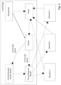
- This data is collected from machine 1, machine... to machine n and clustered by an observer, e.g. according to the same or similar machine configurations, the same processes and/or the same or similar materials to be processed.
- These clusters are evaluated and form training data for a customer-specific model, in particular for determining and selecting at least one suitable machine 1.1 in order to operate other machines, e.g. in the customer's machine park, with the results of the evaluation through federated learning or "swarm knowledge".
- the model can output selection options in advance in order to recommend a suitable machine to a user, for example, based on knowledge of the machine configuration.
- the machine manufacturer is also interested in the machine operator providing at least extracts of the algorithms generated "on edge" in the machine manufacturer's cloud.
- the manufacturer collects the extracts of the algorithms from as many machine operators (customers) as possible, i.e. the content released by customers, compares them and thus sharpens the generation of a cross-customer model (deep learning).
- machine control 1.2 for a machine 1.1 for processing plastics and other plasticizable materials, provided that machine control 1.2 is set up, designed and/or constructed to carry out the method accordingly.
- the advantages of the method arise from the use of a computer program product with a program code stored on a computer-readable medium, so that the method can be carried out using the program code.
Landscapes
- Engineering & Computer Science (AREA)
- Manufacturing & Machinery (AREA)
- Physics & Mathematics (AREA)
- Theoretical Computer Science (AREA)
- General Engineering & Computer Science (AREA)
- General Physics & Mathematics (AREA)
- Mechanical Engineering (AREA)
- Automation & Control Theory (AREA)
- Evolutionary Computation (AREA)
- Geometry (AREA)
- Computer Hardware Design (AREA)
- Quality & Reliability (AREA)
- Injection Moulding Of Plastics Or The Like (AREA)
Claims (18)
- Procédé mis en oeuvre par ordinateur pour la détermination d'au moins une machine (1.1) pour la transformation de matières plastiques et d'autres matériaux plastifiables sur la base de critères déterminés et/ou déterminables pour une production d'au moins une pièce (2.14), ce procédé comprenant les étapes consistant à :(a) mettre à disposition une banque de données de référence (DR) avec des données de machine de référence (2.4), comprenant des ensembles de données partielles de référence (EDPR) nécessaires pour la détermination de paramètres de machine, des paramètres de machine étant associés à chaque ensemble de données partielles de référence,(b) mettre à disposition des données d'utilisateur (2.3) par l'intermédiaire d'une interface utilisateur (2.1) en tant que critères déterminés et/ou déterminables dans une mémoire de données (2.2), lesquelles données utilisateur (2.3) comprennent des données, en particulier des données de CAO, nécessaires pour la fabrication d'au moins une pièce (2.14) et comprennent en outre au moins un groupe des données suivantes :- données caractéristiques du matériau à transformer,- données de machine caractéristiques de consigne,- données de processus de consigne,(c) exécuter une simulation pour la fabrication de la ou des pièce(s) (2.14) sur une machine (1.1) par génération d'ensembles de données de simulation (DS) et/ou lecture d'ensembles de données de simulation (DS) générées lors de la fabrication d'au moins une pièce (2.14) sur la machine (1.1) sur la base des données d'utilisateur (2.3),(d) segmenter les ensembles de données de simulation (DS) pour l'extraction d'ensembles de données partielles (EDP), les ensembles de données partielles concernant des paramètres de machine du côté de la machine, avec lesquels une machine (1.1) doit être pilotée pour la fabrication de la ou des pièce(s) (2.14),(e) mettre en accord les ensembles de données partielles (EDP) avec les ensembles de données partielles de référence (EDPR) provenant de la banque de données de référence (DR) sur des correspondances partielles,(f) émettre un minimum requis (MR) au niveau d'une machine (1.1) ou unité de machine lors de la fabrication de la ou des pièce(s) (2.14) sur la base des correspondances partielles,
caractérisé(g) en ce qu'au moins à partir d'au moins deux éléments, comprenant les données utilisateur (2.3), les ensembles de données de simulation (DS), les ensembles de données partielles (EDP) et les minima requis (MR) provenant de plusieurs machines sont collectés et ensuite regroupés suivant des configurations de machine identiques ou similaires, des processus identiques et/ou des matériaux à transformer identiques ou similaires, des groupes sont formés et ces groupes sont exploités pour piloter par apprentissage fédéré des machines avec un minimum requis (MR) adapté suite aux résultats de l'exploitation,(h) par la détermination de machines (1.1) ou d'unités de machine disponibles à partir des données de machine de référence (2.4),(i) la mise en accord du minimum requis (MR) avec les machines (1.1) ou les unités de machine disponibles pour la détermination d'au moins une machine (1.1) ou unité de machine appropriée pour la fabrication de la ou des pièce(s) (2.14),(j) le pilotage de la machine (1.1) ou de l'unité de machine pour la fabrication de la ou des pièces (2.14). - Procédé selon la revendication 1, caractérisé en ce qu'après la détermination de la machine (1.1) ou unité de machine appropriée suivant l'étape (1), une machine ou unité de machine appropriée est choisie dans un parc de machines d'un utilisateur pour la constitution de la machine appropriée et/ou lorsqu'une machine appropriée est présente sur le marché en cas de présence d'au moins un fournisseur, une fabrication de la pièce à fabriquer (2.14) est proposée pour l'opération sur la machine appropriée du ou des fournisseur(s).
- Procédé selon la revendication 1 ou 2, caractérisé en ce qu'après la détermination d'une machine (1.1) ou unité de machine appropriée suivant l'étape (i), une machine appropriée est configurée par le fabricant en correspondance avec le minimum requis (MR) et/ou est déterminée globalement ou localement, là où se trouvent des unités de machine appropriées, pour constituer une machine (1.1) pour la fabrication de la ou des pièce(s) (2.14).
- Procédé selon l'une des revendications précédentes, caractérisé en ce que les données d'utilisateur (2.3) comprenant des préférences d'utilisateur (3.1), qui peuvent être fixées au moyen d'une unité de réglage (140) linéairement ou de façon discrète sur la base d'un ensemble de paramètres défini et en ce qu'une modification du minimum requis (MA) est analysée sur la base des préférences d'utilisateur (3.1) et transmise.
- Procédé selon l'une des revendications précédentes, caractérisé en ce que lors de la segmentation de l'ensemble de données de simulation (DS) des données d'utilisateur (2.3) sont aussi segmentées en plus ou séparément de l'extraction d'ensembles de données partielles (EDP).
- Procédé selon l'une des revendications précédentes, caractérisé en ce que le procédé est mise en oeuvre sur une machine de moulage par injection ou sur une machine d'opération supplémentaire sur des pièces.
- Procédé selon l'une des revendications précédentes, caractérisé en ce que la simulation pour la fabrication de la ou des pièces (2.14) est une simulation de remplissage pour le remplissage d'un moule d'outil de moulage par injection (unité d'outils 1.5) ou une simulation d'une fabrication de pièce lors de l'opération supplémentaire et/ou une simulation d'écoulement d'un processus de plastification du matériau plastifiable dans une unité de plastification (1.7).
- Procédé selon l'une des revendications précédentes, caractérisé en ce qu'un système auto-apprenant est associé à la banque de données de référence (DR), des données de machine de référence (2.4) étant fournies à la banque de données de référence et segmentées et groupées, les ensembles de données de simulation (DS) et les ensembles de données partielles étant pour cela de préférence introduits dans une couche d'entrée d'un dispositif à IA ou d'un canal de données avec un dispositif à IA.
- Procédé selon l'une des revendications précédentes, caractérisé par les étapes suivantes :- comparaison des résultats de l'exploitation au moins partiellement les uns aux autres, de préférence sur la base d'un cloud, et détermination des résultats de la comparaison,- affinement des données de machine de référence (2.4) nécessaires pour le procédé sur la base des résultats de la comparaison.
- Système mise en oeuvre par ordinateur pour la détermination d'au moins une machine (1.1) pour la transformation de matières plastiques et d'autre matériaux plastifiables sur la base de critères déterminés et/ou déterminables pour une production d'au moins une pièce (2.14), ce système comprenant les composants suivants :- une banque de données de référence (DR) avec des données de machine de référence (2.4), comprenant des ensembles de données partielles de référence (EDPR) nécessaires pour la détermination de paramètres de machine, des paramètres de machine étant associés à chaque ensemble de données partielles de référence,- une interface utilisateur (2.1), qui est configurée pour mettre à disposition des données d'utilisateur (2.3) en tant que critères déterminés et/ou déterminables dans une mémoire de données (2.2), lesquelles données d'utilisateur (2.3) comprenant des données, en particulier des données de CAO, nécessaires pour la fabrication d'au moins une pièce (2.14) et comprenant en outre au moins un groupe des données suivantes :- données caractéristiques du matériau à transformer,- données caractéristiques de machine de consigne,- des données de processus de consigne,- une unité de simulation (2.7) qui est configurée pour simuler, sur la base des données d'utilisateur (2.3), la fabrication de la ou des pièce(s) (2.14) sur une machine (1.1) par génération d'ensembles de données de simulation (DS) et/ou une unité de lecture qui est configurée pour lire, lors de la fabrication d'au moins une pièce, sur la base des données d'utilisateur, des ensembles de données de simulation (DS) générés sur la machine,- une unité de segmentation (2.8), qui est configurée, pour segmenter les ensembles de données de simulation (DS) pour l'extraction d'ensembles de données partielles (EDP), les ensembles de données partielles (EDP) concernant des paramètres de machine du côté de la machine, avec lesquels une machine (1.1) doit être pilotée pour la fabrication de la ou des pièce(s) (2.14),- une première unité de comparaison avec un modèle (2.9), qui est configurées pour comparer les ensembles de données partielles (EDP) avec les ensembles de données partielles de référence (EDPR) de la banque de données de référence (DR) sur des correspondances partielles,- une unité d'analyse (2.10), qui est configurée pour déterminer un minimum requis (MR) au niveau d'une machine (1.1) ou unité de machine lors de la fabrication de la ou des pièce(s) (2.14) sur la base de correspondances partielles et le transmettre à une unité de transmission (2.12),caractérisé en ce que le système présente les autres composants suivants :- une deuxième unité de comparaison avec un modèle (2.11), qui est configurée au moins pour rassembler au moins deux des éléments comprenant les données d'utilisateur (2.3), les ensembles de données de simulation (DS), les ensembles de données partielles (EDP) et les minima requis (MR) provenant de plusieurs machines, et à partir de cela, de former de manière groupée suivant des configurations de machine identiques ou similaires, les mêmes processus et/ou des matériaux identiques ou similaires, des groupes et d'exploiter ces groupes pour piloter des machines par apprentissage fédéré avec un minimum requis (MR) adapté suite aux résultats de l'exploitation,- la deuxième unité de comparaison avec un modèle (2.11) étant configurée, pour mettre en accord le minimum requis (MR) avec les machines (1.1) ou unités de machines disponibles déterminées à partir des données de machine de référence (2.4) pour la détermination d'au moins une machine (1.1) ou unité de machine appropriée pour la fabrication de la ou des pièce(s) (2.14),- une machine (1.1) ou unité de machine appropriée qui est configurée pour fabriquer la ou les pièce(s) (2.14) selon le minimum requis (MR).
- Système selon la revendication 10, caractérisé en ce qu'après la détermination d'une machine (1.1) ou unité de machine appropriée, un configurateur (2.5) est prévu et configuré pour configurer et/ou fabriquer une machine ou unité de machine appropriée chez le fabricant et/ou un système de recherche global ou local (150) est prévu et configuré pour déterminer globalement ou localement où se trouvent des unités de machine appropriées pour constituer une machine pour la fabrication de la ou des pièce(s) (2.14).
- Système selon la revendication 10 ou 11, caractérisé en ce que l'interface utilisateur (2.1) est configurée pour introduire des préférences utilisateur (3.1) qui peuvent être fixées au moyen d'une unité de réglage (140) de façon linéaire ou discrète sur la base d'un ensemble de paramètres définis, et en ce que l'unité d'analyse (2.10) est configurée pour modifier le minimum requis (MR) sur la base des préférences utilisateur.
- Système selon l'une des revendications 10 à 12, caractérisé en ce que l'unité de segmentation (2.8) est configurée pour segmenter, outre les ensembles de données de simulation (DS), les données d'utilisateur (2.3) en plus ou séparément de l'extraction à partir d'ensembles de données partielles (EDP).
- Système selon l'une des revendications 10 à 13, caractérisé en ce que le système est prévu sur une machine de moulage par injection ou sur une machine pour une opération supplémentaire sur des pièces.
- Système selon l'une des revendications 10 à 14, caractérisé en ce que la simulation pour la fabrication de la ou des pièce(s) (2.14) est une simulation de remplissage pour le remplissage d'un moule d'outil de moulage par injection (unité d'outil 15) ou une simulation d'une constitution de pièce lors d'une opération supplémentaire et/ou une simulation d'écoulement d'un processus de plastification du matériau plastifiable dans une unité de plastification (1.7).
- Système selon l'une des revendications 11 à 15, caractérisé en ce qu'un système auto-apprenant est associé à la banque de données de référence (DR) et configuré pour segmenter et grouper les données de machine de référence (2.4), les ensembles de données de simulation (DS) et les ensembles de données partielles étant de de préférence introduits dans une couche d'entrée d'un dispositif à IA ou d'un canal de données avec un dispositif à IA.
- Commande de machine (1.2) pour une machine pour la transformation de matières plastiques et d'autres matériaux plastifiables, caractérisée en ce que cette commande de machine (1.2) est configurée, mise en oeuvre et/ou construite pour mettre le procédé de détermination d'au moins une machine (1.1) selon l'une des revendications 1 à 9.
- Produit avec un programme d'ordinateur ayant un code programme, qui est stocké sur un milieu lisible par un ordinateur, pour la mise en oeuvre d'un procédé de détermination d'au moins une machine (1.1) selon l'une des revendications 1 à 9.
Applications Claiming Priority (2)
| Application Number | Priority Date | Filing Date | Title |
|---|---|---|---|
| DE102022105432.2A DE102022105432A1 (de) | 2022-03-08 | 2022-03-08 | Computerimplementiertes Verfahren und System zur Bestimmung wenigstens einer Maschine |
| PCT/EP2023/055848 WO2023170122A1 (fr) | 2022-03-08 | 2023-03-08 | Procédé et système mis en œuvre par ordinateur permettant de déterminer au moins une machine |
Publications (3)
| Publication Number | Publication Date |
|---|---|
| EP4274723A1 EP4274723A1 (fr) | 2023-11-15 |
| EP4274723B1 true EP4274723B1 (fr) | 2025-01-22 |
| EP4274723C0 EP4274723C0 (fr) | 2025-01-22 |
Family
ID=85556799
Family Applications (1)
| Application Number | Title | Priority Date | Filing Date |
|---|---|---|---|
| EP23710007.8A Active EP4274723B1 (fr) | 2022-03-08 | 2023-03-08 | Procédé et système mis en oeuvre par ordinateur permettant de déterminer au moins une machine |
Country Status (5)
| Country | Link |
|---|---|
| US (1) | US20250232082A1 (fr) |
| EP (1) | EP4274723B1 (fr) |
| CN (1) | CN118742432A (fr) |
| DE (1) | DE102022105432A1 (fr) |
| WO (1) | WO2023170122A1 (fr) |
Families Citing this family (1)
| Publication number | Priority date | Publication date | Assignee | Title |
|---|---|---|---|---|
| JP2025030637A (ja) * | 2023-08-24 | 2025-03-07 | セイコーエプソン株式会社 | 射出成形装置 |
Family Cites Families (13)
| Publication number | Priority date | Publication date | Assignee | Title |
|---|---|---|---|---|
| US6816820B1 (en) | 1999-09-24 | 2004-11-09 | Moldflow Ireland, Ltd. | Method and apparatus for modeling injection of a fluid in a mold cavity |
| TW584591B (en) | 2000-06-08 | 2004-04-21 | Mirle Automation Corp | Method of setting parameters for injection molding machine |
| JP3824503B2 (ja) | 2001-06-11 | 2006-09-20 | 日精樹脂工業株式会社 | 射出成形機の成形条件設定方法 |
| US20020193972A1 (en) | 2001-06-14 | 2002-12-19 | Ntn Corporation | Workshop facility design and operation support system enabling verification of the entire workshop to be performed easily |
| AT500188B1 (de) | 2001-09-14 | 2007-03-15 | Voest Alpine Ind Anlagen | Rechnergestützter konfigurator zum konfigurieren einer anlage der grundstoffindustrie |
| DE20321699U1 (de) | 2003-11-12 | 2009-01-15 | Siemens Aktiengesellschaft | Rechner zum Durchführen eines Simulationsverfahrens für eine Bearbeitung eines Werkstücks durch eine Werkzeugmaschine |
| US7580771B2 (en) | 2004-10-19 | 2009-08-25 | Husky Injection Molding Systems Ltd. | Intelligent molding environment and method of configuring a molding system |
| DE102005047543A1 (de) | 2005-09-30 | 2007-04-05 | Siemens Ag | Verfahren zur Simulation eines Steuerungs- und/oder Maschinenverhaltens einer Werkzeugmaschine oder einer Produktionsmaschine |
| DE102013008245A1 (de) | 2013-05-15 | 2014-11-20 | Arburg Gmbh + Co. Kg | Verfahren zum Betreiben einer Maschine zur Verarbeitung von Kunststoffen |
| CN107111297B (zh) | 2014-10-31 | 2021-03-26 | 制造业大数据有限公司 | 用于由至少一台计算机数控机器加工的工件的部件分析的计算机实现方法 |
| DE102015107025B4 (de) | 2015-05-06 | 2021-01-21 | Bt Bayern Treuhand Management & Technologie Gmbh | Verfahren und Prozessparameterwert-Ermittlungseinrichtung zur Ermittlung und Anzeige von Prozessparameterwerten in einem Spritzgussprozess, Verfahren zur Steuerung und Steuereinrichtung für eine Spritzgießanlage sowie Spritzgießanlage |
| DE102018111603A1 (de) | 2018-05-15 | 2019-11-21 | Hermann Müller | Verfahren und Vorrichtung zum Konfigurieren eines roboter-gestützten Bearbeitungssystems |
| JP7099977B2 (ja) | 2019-03-27 | 2022-07-12 | 株式会社日立製作所 | 射出成形解析方法および射出成形解析システム |
-
2022
- 2022-03-08 DE DE102022105432.2A patent/DE102022105432A1/de not_active Withdrawn
-
2023
- 2023-03-08 EP EP23710007.8A patent/EP4274723B1/fr active Active
- 2023-03-08 US US18/845,107 patent/US20250232082A1/en active Pending
- 2023-03-08 CN CN202380025812.9A patent/CN118742432A/zh active Pending
- 2023-03-08 WO PCT/EP2023/055848 patent/WO2023170122A1/fr not_active Ceased
Also Published As
| Publication number | Publication date |
|---|---|
| CN118742432A (zh) | 2024-10-01 |
| US20250232082A1 (en) | 2025-07-17 |
| WO2023170122A1 (fr) | 2023-09-14 |
| EP4274723A1 (fr) | 2023-11-15 |
| DE102022105432A1 (de) | 2023-09-14 |
| EP4274723C0 (fr) | 2025-01-22 |
Similar Documents
| Publication | Publication Date | Title |
|---|---|---|
| DE102017131032B4 (de) | Verfahren zum Einstellen einer Formgebungsmaschine | |
| EP2953778B2 (fr) | Procédé permettant de faire fonctionner une machine de traitement de matières plastiques | |
| DE102017131025A1 (de) | Verfahren zur Optimierung eines Prozessoptimierungssystems und Verfahren zum Simulieren eines Formgebungsprozesses | |
| EP3892440A1 (fr) | Procédé de réglage d'une machine de moulage par injection | |
| EP3710223B1 (fr) | Procédé de commande d'une machine de traitement de matières plastiques | |
| EP2824450B1 (fr) | Utilisation d'un procede d'evaluation d'un resultat d'une analyse thermique, produit de programme informatique et combinaison d'une installation de production ou de traitement et systeme pour la realisation de l'utilisation | |
| DE102017116459B4 (de) | Cad/cam-cnc-integriertes system | |
| EP3479178B1 (fr) | Regulation d'un systeme de production basé sur une simulation | |
| DE112018007741B4 (de) | Maschinenlernvorrichtung und vorrichtung zur erzeugung vonprogrammen für eine numerisch gesteuerte bearbeitung | |
| EP1855867B1 (fr) | Procede pour la commande et l'utilisation d'une cellule de production et dispositif de commande | |
| DE102022102395A1 (de) | Verfahren und Vorrichtung zur Reduzierung des Nachbearbeitungsaufwands an Urform-Kavitäten vor deren Verwendung im Serienbetrieb | |
| EP4274723A1 (fr) | Procédé et système mis en oeuvre par ordinateur permettant de déterminer au moins une machine | |
| EP4327171B1 (fr) | Procédé de commande de processus sur des machines de traitement de matières plastiques | |
| EP4338925A1 (fr) | Procédé mis en uvre par ordinateur pour déterminer une valeur de poids de prédiction d'un produit fabriqué par un dispositif de moulage par injection, procédé de commande et système de commande | |
| EP2348430A2 (fr) | Système de formation d'un préformé | |
| AT520601B1 (de) | Verfahren zur Ansicht und Auswahl von Produktionsmitteln, insbesondere peripheren Geräten, für die Spritzgießindustrie, sowie eine Industrieanlage | |
| EP4294621B1 (fr) | Procédé et dispositif de détermination de l'usure d'un dispositif de traitement de matières plastiques | |
| AT518965B1 (de) | Visualisierung einer Produktionsanordnung | |
| EP4441569B1 (fr) | Procédé, ensemble et logiciel de configuration et/ou de programmation d'un composant d'automatisation industrielle | |
| DE102015015811A1 (de) | Verfahren und eine Simulationsvorrichtung zur Simulation einer fiktiven Konfiguration einer Formgebungsanlage | |
| WO2023242396A1 (fr) | Procédé mis en œuvre par ordinateur et système pour transmettre un ensemble de données de commande pour une machine | |
| DE102024105485A1 (de) | Verfahren zum Bedienen einer Formgebungsmaschine | |
| AT522623A1 (de) | Verfahren zum Überprüfen der Eignung eines Formgebungswerkzeugs | |
| EP3056954A1 (fr) | Détermination d'informations de commande lors de la fabrication d'une machine |
Legal Events
| Date | Code | Title | Description |
|---|---|---|---|
| STAA | Information on the status of an ep patent application or granted ep patent |
Free format text: STATUS: UNKNOWN |
|
| STAA | Information on the status of an ep patent application or granted ep patent |
Free format text: STATUS: THE INTERNATIONAL PUBLICATION HAS BEEN MADE |
|
| PUAI | Public reference made under article 153(3) epc to a published international application that has entered the european phase |
Free format text: ORIGINAL CODE: 0009012 |
|
| STAA | Information on the status of an ep patent application or granted ep patent |
Free format text: STATUS: REQUEST FOR EXAMINATION WAS MADE |
|
| 17P | Request for examination filed |
Effective date: 20230809 |
|
| AK | Designated contracting states |
Kind code of ref document: A1 Designated state(s): AL AT BE BG CH CY CZ DE DK EE ES FI FR GB GR HR HU IE IS IT LI LT LU LV MC ME MK MT NL NO PL PT RO RS SE SI SK SM TR |
|
| GRAP | Despatch of communication of intention to grant a patent |
Free format text: ORIGINAL CODE: EPIDOSNIGR1 |
|
| STAA | Information on the status of an ep patent application or granted ep patent |
Free format text: STATUS: GRANT OF PATENT IS INTENDED |
|
| DAV | Request for validation of the european patent (deleted) | ||
| DAX | Request for extension of the european patent (deleted) | ||
| INTG | Intention to grant announced |
Effective date: 20240809 |
|
| GRAS | Grant fee paid |
Free format text: ORIGINAL CODE: EPIDOSNIGR3 |
|
| GRAA | (expected) grant |
Free format text: ORIGINAL CODE: 0009210 |
|
| STAA | Information on the status of an ep patent application or granted ep patent |
Free format text: STATUS: THE PATENT HAS BEEN GRANTED |
|
| AK | Designated contracting states |
Kind code of ref document: B1 Designated state(s): AL AT BE BG CH CY CZ DE DK EE ES FI FR GB GR HR HU IE IS IT LI LT LU LV MC ME MK MT NL NO PL PT RO RS SE SI SK SM TR |
|
| REG | Reference to a national code |
Ref country code: GB Ref legal event code: FG4D Free format text: NOT ENGLISH |
|
| REG | Reference to a national code |
Ref country code: CH Ref legal event code: EP |
|
| REG | Reference to a national code |
Ref country code: IE Ref legal event code: FG4D Free format text: LANGUAGE OF EP DOCUMENT: GERMAN |
|
| REG | Reference to a national code |
Ref country code: DE Ref legal event code: R096 Ref document number: 502023000491 Country of ref document: DE |
|
| U01 | Request for unitary effect filed |
Effective date: 20250206 |
|
| U07 | Unitary effect registered |
Designated state(s): AT BE BG DE DK EE FI FR IT LT LU LV MT NL PT RO SE SI Effective date: 20250212 |
|
| U20 | Renewal fee for the european patent with unitary effect paid |
Year of fee payment: 3 Effective date: 20250225 |
|
| PG25 | Lapsed in a contracting state [announced via postgrant information from national office to epo] |
Ref country code: RS Free format text: LAPSE BECAUSE OF FAILURE TO SUBMIT A TRANSLATION OF THE DESCRIPTION OR TO PAY THE FEE WITHIN THE PRESCRIBED TIME-LIMIT Effective date: 20250422 |
|
| PG25 | Lapsed in a contracting state [announced via postgrant information from national office to epo] |
Ref country code: PL Free format text: LAPSE BECAUSE OF FAILURE TO SUBMIT A TRANSLATION OF THE DESCRIPTION OR TO PAY THE FEE WITHIN THE PRESCRIBED TIME-LIMIT Effective date: 20250122 |
|
| PG25 | Lapsed in a contracting state [announced via postgrant information from national office to epo] |
Ref country code: ES Free format text: LAPSE BECAUSE OF FAILURE TO SUBMIT A TRANSLATION OF THE DESCRIPTION OR TO PAY THE FEE WITHIN THE PRESCRIBED TIME-LIMIT Effective date: 20250122 |
|
| PG25 | Lapsed in a contracting state [announced via postgrant information from national office to epo] |
Ref country code: IS Free format text: LAPSE BECAUSE OF FAILURE TO SUBMIT A TRANSLATION OF THE DESCRIPTION OR TO PAY THE FEE WITHIN THE PRESCRIBED TIME-LIMIT Effective date: 20250522 Ref country code: NO Free format text: LAPSE BECAUSE OF FAILURE TO SUBMIT A TRANSLATION OF THE DESCRIPTION OR TO PAY THE FEE WITHIN THE PRESCRIBED TIME-LIMIT Effective date: 20250422 |
|
| PG25 | Lapsed in a contracting state [announced via postgrant information from national office to epo] |
Ref country code: HR Free format text: LAPSE BECAUSE OF FAILURE TO SUBMIT A TRANSLATION OF THE DESCRIPTION OR TO PAY THE FEE WITHIN THE PRESCRIBED TIME-LIMIT Effective date: 20250122 |
|
| PG25 | Lapsed in a contracting state [announced via postgrant information from national office to epo] |
Ref country code: GR Free format text: LAPSE BECAUSE OF FAILURE TO SUBMIT A TRANSLATION OF THE DESCRIPTION OR TO PAY THE FEE WITHIN THE PRESCRIBED TIME-LIMIT Effective date: 20250423 |
|
| PG25 | Lapsed in a contracting state [announced via postgrant information from national office to epo] |
Ref country code: SM Free format text: LAPSE BECAUSE OF FAILURE TO SUBMIT A TRANSLATION OF THE DESCRIPTION OR TO PAY THE FEE WITHIN THE PRESCRIBED TIME-LIMIT Effective date: 20250122 |
|
| PG25 | Lapsed in a contracting state [announced via postgrant information from national office to epo] |
Ref country code: MC Free format text: LAPSE BECAUSE OF FAILURE TO SUBMIT A TRANSLATION OF THE DESCRIPTION OR TO PAY THE FEE WITHIN THE PRESCRIBED TIME-LIMIT Effective date: 20250122 |
|
| PG25 | Lapsed in a contracting state [announced via postgrant information from national office to epo] |
Ref country code: CZ Free format text: LAPSE BECAUSE OF FAILURE TO SUBMIT A TRANSLATION OF THE DESCRIPTION OR TO PAY THE FEE WITHIN THE PRESCRIBED TIME-LIMIT Effective date: 20250122 |
|
| PG25 | Lapsed in a contracting state [announced via postgrant information from national office to epo] |
Ref country code: SK Free format text: LAPSE BECAUSE OF FAILURE TO SUBMIT A TRANSLATION OF THE DESCRIPTION OR TO PAY THE FEE WITHIN THE PRESCRIBED TIME-LIMIT Effective date: 20250122 |
|
| PLBE | No opposition filed within time limit |
Free format text: ORIGINAL CODE: 0009261 |
|
| STAA | Information on the status of an ep patent application or granted ep patent |
Free format text: STATUS: NO OPPOSITION FILED WITHIN TIME LIMIT |
|
| REG | Reference to a national code |
Ref country code: CH Ref legal event code: L10 Free format text: ST27 STATUS EVENT CODE: U-0-0-L10-L00 (AS PROVIDED BY THE NATIONAL OFFICE) Effective date: 20251203 |
|
| 26N | No opposition filed |
Effective date: 20251023 |
|
| PG25 | Lapsed in a contracting state [announced via postgrant information from national office to epo] |
Ref country code: IE Free format text: LAPSE BECAUSE OF NON-PAYMENT OF DUE FEES Effective date: 20250308 |
|
| REG | Reference to a national code |
Ref country code: CH Ref legal event code: U11 Free format text: ST27 STATUS EVENT CODE: U-0-0-U10-U11 (AS PROVIDED BY THE NATIONAL OFFICE) Effective date: 20260401 |
|
| U20 | Renewal fee for the european patent with unitary effect paid |
Year of fee payment: 4 Effective date: 20260302 |