EP4274785B1 - Récipient alimentaire en pulpe de fibres - Google Patents
Récipient alimentaire en pulpe de fibres Download PDFInfo
- Publication number
- EP4274785B1 EP4274785B1 EP21802720.9A EP21802720A EP4274785B1 EP 4274785 B1 EP4274785 B1 EP 4274785B1 EP 21802720 A EP21802720 A EP 21802720A EP 4274785 B1 EP4274785 B1 EP 4274785B1
- Authority
- EP
- European Patent Office
- Prior art keywords
- container
- rim
- side walls
- junction
- rim part
- Prior art date
- Legal status (The legal status is an assumption and is not a legal conclusion. Google has not performed a legal analysis and makes no representation as to the accuracy of the status listed.)
- Active
Links
Images



Classifications
-
- B—PERFORMING OPERATIONS; TRANSPORTING
- B65—CONVEYING; PACKING; STORING; HANDLING THIN OR FILAMENTARY MATERIAL
- B65D—CONTAINERS FOR STORAGE OR TRANSPORT OF ARTICLES OR MATERIALS, e.g. BAGS, BARRELS, BOTTLES, BOXES, CANS, CARTONS, CRATES, DRUMS, JARS, TANKS, HOPPERS, FORWARDING CONTAINERS; ACCESSORIES, CLOSURES, OR FITTINGS THEREFOR; PACKAGING ELEMENTS; PACKAGES
- B65D1/00—Rigid or semi-rigid containers having bodies formed in one piece, e.g. by casting metallic material, by moulding plastics, by blowing vitreous material, by throwing ceramic material, by moulding pulped fibrous material or by deep-drawing operations performed on sheet material
- B65D1/34—Trays or like shallow containers
-
- B—PERFORMING OPERATIONS; TRANSPORTING
- B65—CONVEYING; PACKING; STORING; HANDLING THIN OR FILAMENTARY MATERIAL
- B65D—CONTAINERS FOR STORAGE OR TRANSPORT OF ARTICLES OR MATERIALS, e.g. BAGS, BARRELS, BOTTLES, BOXES, CANS, CARTONS, CRATES, DRUMS, JARS, TANKS, HOPPERS, FORWARDING CONTAINERS; ACCESSORIES, CLOSURES, OR FITTINGS THEREFOR; PACKAGING ELEMENTS; PACKAGES
- B65D1/00—Rigid or semi-rigid containers having bodies formed in one piece, e.g. by casting metallic material, by moulding plastics, by blowing vitreous material, by throwing ceramic material, by moulding pulped fibrous material or by deep-drawing operations performed on sheet material
- B65D1/40—Details of walls
- B65D1/42—Reinforcing or strengthening parts or members
-
- B—PERFORMING OPERATIONS; TRANSPORTING
- B65—CONVEYING; PACKING; STORING; HANDLING THIN OR FILAMENTARY MATERIAL
- B65D—CONTAINERS FOR STORAGE OR TRANSPORT OF ARTICLES OR MATERIALS, e.g. BAGS, BARRELS, BOTTLES, BOXES, CANS, CARTONS, CRATES, DRUMS, JARS, TANKS, HOPPERS, FORWARDING CONTAINERS; ACCESSORIES, CLOSURES, OR FITTINGS THEREFOR; PACKAGING ELEMENTS; PACKAGES
- B65D21/00—Nestable, stackable or joinable containers; Containers of variable capacity
- B65D21/02—Containers specially shaped, or provided with fittings or attachments, to facilitate nesting, stacking, or joining together
- B65D21/0233—Nestable containers
-
- B—PERFORMING OPERATIONS; TRANSPORTING
- B65—CONVEYING; PACKING; STORING; HANDLING THIN OR FILAMENTARY MATERIAL
- B65D—CONTAINERS FOR STORAGE OR TRANSPORT OF ARTICLES OR MATERIALS, e.g. BAGS, BARRELS, BOTTLES, BOXES, CANS, CARTONS, CRATES, DRUMS, JARS, TANKS, HOPPERS, FORWARDING CONTAINERS; ACCESSORIES, CLOSURES, OR FITTINGS THEREFOR; PACKAGING ELEMENTS; PACKAGES
- B65D25/00—Details of other kinds or types of rigid or semi-rigid containers
- B65D25/14—Linings or internal coatings
-
- B—PERFORMING OPERATIONS; TRANSPORTING
- B65—CONVEYING; PACKING; STORING; HANDLING THIN OR FILAMENTARY MATERIAL
- B65D—CONTAINERS FOR STORAGE OR TRANSPORT OF ARTICLES OR MATERIALS, e.g. BAGS, BARRELS, BOTTLES, BOXES, CANS, CARTONS, CRATES, DRUMS, JARS, TANKS, HOPPERS, FORWARDING CONTAINERS; ACCESSORIES, CLOSURES, OR FITTINGS THEREFOR; PACKAGING ELEMENTS; PACKAGES
- B65D65/00—Wrappers or flexible covers; Packaging materials of special type or form
- B65D65/38—Packaging materials of special type or form
- B65D65/46—Applications of disintegrable, dissolvable or edible materials
- B65D65/466—Bio- or photodegradable packaging materials
-
- B—PERFORMING OPERATIONS; TRANSPORTING
- B31—MAKING ARTICLES OF PAPER, CARDBOARD OR MATERIAL WORKED IN A MANNER ANALOGOUS TO PAPER; WORKING PAPER, CARDBOARD OR MATERIAL WORKED IN A MANNER ANALOGOUS TO PAPER
- B31B—MAKING CONTAINERS OF PAPER, CARDBOARD OR MATERIAL WORKED IN A MANNER ANALOGOUS TO PAPER
- B31B2120/00—Construction of rigid or semi-rigid containers
- B31B2120/40—Construction of rigid or semi-rigid containers lined or internally reinforced
- B31B2120/402—Construction of rigid or semi-rigid containers lined or internally reinforced by applying a liner to already made boxes, e.g. opening or distending of the liner or the box
-
- B—PERFORMING OPERATIONS; TRANSPORTING
- B65—CONVEYING; PACKING; STORING; HANDLING THIN OR FILAMENTARY MATERIAL
- B65D—CONTAINERS FOR STORAGE OR TRANSPORT OF ARTICLES OR MATERIALS, e.g. BAGS, BARRELS, BOTTLES, BOXES, CANS, CARTONS, CRATES, DRUMS, JARS, TANKS, HOPPERS, FORWARDING CONTAINERS; ACCESSORIES, CLOSURES, OR FITTINGS THEREFOR; PACKAGING ELEMENTS; PACKAGES
- B65D2565/00—Wrappers or flexible covers; Packaging materials of special type or form
-
- B—PERFORMING OPERATIONS; TRANSPORTING
- B65—CONVEYING; PACKING; STORING; HANDLING THIN OR FILAMENTARY MATERIAL
- B65D—CONTAINERS FOR STORAGE OR TRANSPORT OF ARTICLES OR MATERIALS, e.g. BAGS, BARRELS, BOTTLES, BOXES, CANS, CARTONS, CRATES, DRUMS, JARS, TANKS, HOPPERS, FORWARDING CONTAINERS; ACCESSORIES, CLOSURES, OR FITTINGS THEREFOR; PACKAGING ELEMENTS; PACKAGES
- B65D2565/00—Wrappers or flexible covers; Packaging materials of special type or form
- B65D2565/38—Packaging materials of special type or form
-
- B—PERFORMING OPERATIONS; TRANSPORTING
- B65—CONVEYING; PACKING; STORING; HANDLING THIN OR FILAMENTARY MATERIAL
- B65D—CONTAINERS FOR STORAGE OR TRANSPORT OF ARTICLES OR MATERIALS, e.g. BAGS, BARRELS, BOTTLES, BOXES, CANS, CARTONS, CRATES, DRUMS, JARS, TANKS, HOPPERS, FORWARDING CONTAINERS; ACCESSORIES, CLOSURES, OR FITTINGS THEREFOR; PACKAGING ELEMENTS; PACKAGES
- B65D2565/00—Wrappers or flexible covers; Packaging materials of special type or form
- B65D2565/38—Packaging materials of special type or form
- B65D2565/381—Details of packaging materials of special type or form
-
- B—PERFORMING OPERATIONS; TRANSPORTING
- B65—CONVEYING; PACKING; STORING; HANDLING THIN OR FILAMENTARY MATERIAL
- B65D—CONTAINERS FOR STORAGE OR TRANSPORT OF ARTICLES OR MATERIALS, e.g. BAGS, BARRELS, BOTTLES, BOXES, CANS, CARTONS, CRATES, DRUMS, JARS, TANKS, HOPPERS, FORWARDING CONTAINERS; ACCESSORIES, CLOSURES, OR FITTINGS THEREFOR; PACKAGING ELEMENTS; PACKAGES
- B65D2565/00—Wrappers or flexible covers; Packaging materials of special type or form
- B65D2565/38—Packaging materials of special type or form
- B65D2565/381—Details of packaging materials of special type or form
- B65D2565/382—Details of packaging materials of special type or form made of special paper
-
- B—PERFORMING OPERATIONS; TRANSPORTING
- B65—CONVEYING; PACKING; STORING; HANDLING THIN OR FILAMENTARY MATERIAL
- B65D—CONTAINERS FOR STORAGE OR TRANSPORT OF ARTICLES OR MATERIALS, e.g. BAGS, BARRELS, BOTTLES, BOXES, CANS, CARTONS, CRATES, DRUMS, JARS, TANKS, HOPPERS, FORWARDING CONTAINERS; ACCESSORIES, CLOSURES, OR FITTINGS THEREFOR; PACKAGING ELEMENTS; PACKAGES
- B65D2565/00—Wrappers or flexible covers; Packaging materials of special type or form
- B65D2565/38—Packaging materials of special type or form
- B65D2565/381—Details of packaging materials of special type or form
- B65D2565/382—Details of packaging materials of special type or form made of special paper
- B65D2565/383—Details of packaging materials of special type or form made of special paper made of recycled paper
Definitions
- the present invention relates to a container, preferably a container of pulp for the packaging of foods.
- the present invention is particularly suitable to be used in combination with vacuum packaging or modified atmosphere packaging of foods, such as fresh meat or other foods which need to be packed in an enclosed environment, where food is packed in a container and a top film is connected to a top of the container for hermetic sealing the content within the container.
- plastic is not a particularly sustainable material, and there is a need for providing food containers from a more environment-friendly material.
- Containers made of fiber pulp e.g. pulp from wooden fibres or non-wood bio fibres, have also been commonly known for packaging food, such as eggs, fruits, etc.
- a production process of making containers of moulded pulp is commonly known within the technical field, where a fiber material such as recycled paper and/or cardboard and/or other waste papers are processed into a certain concentration of slurry by a pulp mixer. Other materials could be straw, grass, seaweed etc.
- the slurry is used in a moulding machine for forming the containers, which afterwards are dried in a dryer, and pressed into compact shape by e.g. a hot press (after press).
- the above-defined method is just one example of a known manufacturing process.
- a barrier film e.g. a plastic barrier film, which is arranged on at least one side of the container to render the container moist resistant and gas tight/diffusion tight, so that it can be used to contain the wet products, such as fresh meat, and further to allow a hermetic sealing of the content for the purpose of preservation.
- a top film or sheet is sealed over the opening of the container and bonded to the surrounding rim, hereby hermetically sealing the container.
- the barrier film which is arranged on at least one side of the container, can be a film of thermoformable material, which is able to be stretched and formed into conformity with the contoured moulded pulp container, preferably at an inner surface of the container.
- Containers made from plastic are extremely mechanically stable, and such containers have the ability to return from a deformed state (temporary shape) to the original (permanent) shape induced by an external influence, such as a temperature change or an accidental mechanical impact from e.g. processing equipment during forming or packing.
- containers from fiber pulp do not have the same mechanical stability as plastic container, and an even relatively small accidental impact on the pulp container during the packing or manufacturing process renders the package instable, and the pulp container will not return to the original shape. Once a product made from fiber pulp has been deformed, it cannot return entirely to its original shape.
- the pulp container will be subject to forces from the barrier film, which may be arranged on the container via a thermoforming process, in which the barrier film is heated, stretched and pulled down over the inner surfaces of the container.
- the stretchable barrier film will to some degree pull the side walls of the container inwards, hereby deforming and rendering the container somehow hourglass-shaped.
- the pulp containers are arranged in positioning equipment intended for maintaining the containers in a correctly orientated position in relation to the top film/sheet application equipment.
- the container and the container rim lead to the top film/sheet being incorrectly positioned and connected.
- the pulp containers are conveyed through the production line via belt conveyers, which are commonly known within the art.
- the containers may have been subject to unintentional external forces, which renders the containers with a non-original geometry, a problem of the bottom surface of the container being non-planar is created, which results in insufficient contact with the conveyers, further resulting in an undesired movement and rotation of the containers on the belt conveyers.
- Such undesired movement of the containers may result in a blocking of the belt conveyers and/or in the containers not being aligned with the following processing equipment, or even further result in accidental impacts on the containers.
- the container of pulp may be manufactured according to the commonly known processes as discussed above.
- containers made from pulp do not have the same mechanical properties as e.g. containers made from plastic material. If the container from fiber pulp is subjected to unintentional external forces during manufacturing or packing of the food products, the pulp container does not return to its original shape. If the rim of the container has been bent downwards due to an accidental impact on the rim, the upper surface of the rim is no longer planar and no longer parallel with the bottom part. Hereby, the rim is no longer suitable to be connected to the top barrier film, which seals the container.
- the container is arranged with a junction between the side walls and the rim part, where the junction along the rim part follows a line which is non-parallel in relation to a longitudinal direction of the rim part.
- the rim part when exposed to an unintentional external force, will bend downwards/upwards around the moment of inertia reference line (the axis upon which the rim part will rotate), which reference line is depending on the form of the junction.
- junction is a straight line being parallel to the longitudinal direction of the rim part, the moment of inertia reference line will be coincident with the junction.
- the moment of inertia reference line is defined by a straight line extending through the middle of the non-parallel line.
- a part of the junction may follow a parallel line in relation to the trim part, and a part of the junction follows a non-parallel line in relation to the rim part, but in order to establish an optimal result, the non-parallel part defines a substantial part of the junction, such as between one third and the half of the extension of the junction.
- the non-parallel part defines at least 50% of the junction. The greater the extent of the non-planar junction, the greater the moment of inertia of the rim part.
- the non-parallel part may by a straight line, which is arranged non-parallel in relation to the longitudinal direction of the rim part, e.g., a zigzag shape, but may also be a curved line, such as an arc or a series of curves, such as a wave-shaped junction, or even a combination of straight and curved lines.
- a main part of the junction is non-parallel in relation to a longitudinal direction of the rim part.
- the container is made from fiber pulp.
- containers made from fiber pulp do not have the same mechanical stability as plastic container. Therefore, an even relatively small accidental impact on the pulp container during the packing or manufacturing process renders the package instable, and the pulp container will not return to the original shape. Once a product made from fiber pulp has been deformed, it cannot return entirely to its original shape. Therefore, when arranging the above-defined junction in combination with a container made from fiber pulp, it is possible to manufacture a sustainable container with substantially the same strong mechanical properties of the rim part as a container made from a plastic material.
- the junction comprising a non-straight line.
- the junction is wave-shaped and comprises a number of waves having a wavelength with a direction being substantially parallel to the rim part.
- the junction is wave-shaped, such that the wave lengths are arranged with a direction that is substantially parallel to the longitudinal direction of the rim part.
- An inner part of the rim defines a boundary between the wall and the rim part, and as the junction is wave-shaped, the moment of inertia reference line (the axis upon which the rim part will rotate) is defined by a straight line, which extends parallel to the wavelengths between the wave crests and the wave throughs, which corresponds to the wave amplitude.
- the upwardly extending side walls further comprising a reinforcing element below said longitudinal rim part, said junction being arranged between said reinforcing element and said rim part.
- the upwardly extending walls of the container may be arranged with a reinforcing element, which is arranged on the outer surface of the side walls for generating an increased moment of inertia of the rim part along the longitudinal direction thereof.
- the reinforcing element As the reinforcing element is arranged on the outer surface of the side walls, and in connection with the rim art, the reinforcing element generates an increased moment of inertia along the longitudinal direction of the rim part, so that the rim is more capable of withstanding external forces, resulting in the rim maintaining its original planar shape.
- the reinforcing element is a longitudinal reinforcing rib extending substantially parallel to and below the rim part.
- the reinforcing element could comprise a number of distanced individual reinforcing elements arranged below the rim part.
- the longitudinal reinforcing rib is wave-shaped and comprises a number of waves having wavelengths with a direction being substantially parallel to the rim part.
- the longitudinal reinforcing rib is wave-shaped and is arranged on the substantially vertical side walls, such that the wave lengths are arranged with a direction that is substantially parallel to the longitudinal direction of the rim part.
- An inner part of the rim defines a boundary of the reinforcing rib, and as the reinforcing rib is connected to the rim part and the reinforcing rib is wave-shaped, the moment of inertia reference line (the axis upon which the rim part will rotate) is defined by a straight line which extends parallel to the wavelengths between the wave crests and the wave throughs, which corresponds to the wave amplitude.
- the upwardly extending side walls define the wave-shaped rib, the wave-shaped rib having a material thickness substantially equal to the thickness of a remaining part of the upwardly extending side walls.
- the wave-shaped rib is preferably incorporated into the side walls, hereby being defined by the side walls. Arranging the wave-shaped rib as part of, and having the same material thickness as the side walls, decreases the amount of necessary material to be used and establishes the container with maximum volume, and at the same time maintains the stackability of the containers. It is noted that during transportation of the empty manufactured containers, the containers are stacked on top of each other.
- the wave-shaped rib comprises a number of crest and through points being raised in respect to the planes of the outer wall surfaces.
- the wave throughs could be planar with the outer surface of the side walls, but in a preferred embodiment, also the wave throughs are raised from the outer surface of the side walls, hereby increasing the effect of the wave-shaped rib.
- the upwardly extending side walls below the reinforcing element comprise a number of substantially vertical reinforcing ribs extending from the bottom for generating an increased moment of inertia of the upwardly extending side walls, along a direction parallel to the longitudinal direction of the longitudinal rim part, respectively.
- the container comprises a number of substantially vertical reinforcing ribs on the sidewalls, and preferably integrated therewith, for enhancing the stability of the side walls in general.
- the vertical reinforcing ribs extend from the bottom, and preferably from below the bottom, and towards the rim part, the moment of inertia of the walls in a direction parallel with the longitudinal rim is increased. This results in the walls having less tendency to bend inwards, e.g. under the process of thermoforming the barrier film onto the inner surfaces of the container.
- the substantially vertical reinforcing ribs are arranged independently in relation to the junction.
- the substantially vertical reinforcing ribs are preferably arranged independently in relation to the junction.
- the moment of inertia of the upper rim part is not equal to the moment of inertia of the substantially vertical side walls, and the two different parts of the container and the mechanical strength of these two parts have to be dimensioned independently of each other. Therefore, with the term “independently” is meant that the substantially vertical reinforcing ribs do not, or only minimal, contribute to the increased moment of inertia of the rim part.
- the container comprises a barrier for making the container diffusion tight.
- the container comprises a barrier which may be arranged on the inner surfaces of the container or on the outer surfaces of the container which makes the container diffusion tight.
- the container may in alternative embodiment comprise a barrier on both the inner and outer layer in order to shield the fibre material from moisture, from both the inside and the outside of the container.
- the barrier being arranged on the inner wall surfaces, an inner surface of said bottom and on said planar main surface of said rim.
- the barrier covers the inner wall surfaces, the inner bottom surface and/or the main surface of the rim.
- the covering of the inner surfaces of the container makes the walls and bottom parts diffusion tight, and covering the main surface of the rim, establishes a suitable connection surface for the top film/sheet, such that the connection between the two is also diffusion tight.
- the barrier may be a film which is arranged on the inner wall surfaces and the inner bottom surface, preferably by a thermoforming process.
- the barrier film may be provided as a laminate, which comprises a diffusion-tight middle layer of a copolymer, such as ethylene vinyl alcohol, and outer layers having fibre-bonding properties, such as Polyethylene.
- a copolymer such as ethylene vinyl alcohol
- outer layers having fibre-bonding properties such as Polyethylene.
- the middle layer of copolymer such as ethylene vinyl alcohol, provides good diffusion-tight properties of the barrier film, but is not suitable as a material for being thermoformed onto the surface of the pulp container. Therefore, each side of the middle layer is provided with an outer layer of a material suitable for thermoforming and which provides good bonding properties to the surface of the container on the one side and the top film/sheet on the other side.
- the outer layers are preferably made from polyethylene, however, other suitable materials providing the same characteristics may be used.
- the barrier having a thickness of between 20-125 ⁇ m, preferably between 20-80 ⁇ m, most preferred between 20-60 ⁇ m.
- the container When constructing the container, it is crucial to obtain the desired mechanical strength of the container, but also crucial to have as little a product thickness as possible while maintaining the desired mechanical strength. Therefore, it is desirable to provide a barrier film which adds minimal thickness to the product and still provides for the desired effect of the film, i.e. a diffusion-tight container and good bonding properties in relation to the container and the top film/sheet.
- the optimal minimal thickness of the barrier film is achieved with a thickness of the barrier film of approximately 20-125 ⁇ m, preferably between 20-80 ⁇ m, most preferred between 20-60 ⁇ m.
- the increased stretched film will increase the pulling force of the walls as previously described, hereby rendering the container even more hourglass-shaped, but due the reinforcing elements, the container maintains its shape and the main surface of the rim part maintains its orientation being substantially parallel to the bottom plane.
- the present invention it is thus possible to provide a container of fiber pulp with a minimal barrier thickness and maintained mechanical properties.
- the barrier film is peelable from the bottom and wall surfaces.
- the barrier film can be pealed off the container once it has been used for subsequent recycling.
- the container comprises a lower main surface of the bottom part, which when the container is placed on a planar surface, is raised in relation to the remaining lower surface of said bottom part.
- the containers are conveyed on belt conveyers through the production line between individual stations (filling and sealing), where the containers made from pulp have a tendency to rotate and not being aligned with the processing equipment.
- the rotation is a result of the containers being made from pulp.
- Pulp containers do not have the same mechanical strength and precise dimensions as plastic containers, and as the pulp containers may have been subject to unintentional external forces, the bottom of the containers may not be entirely planar. If the containers do not have sufficient contact with the conveyers, they will rotate and the production line will stop.
- the bottom comprises parts which project from the bottom surface, such that when the container is placed on a planar surface, a main portion of the container is raised in relation to the projecting parts.
- the projecting parts ensure constant contact with the conveyors such that variations of the geometry of the container do not cause it to rotate.
- the lower surface of said container on the corners thereof, comprises projecting elements for arranging said lower main surface being raised in relation to the planar surface.
- a lower surface of the bottom part comprises a part having a rough surface structure compared to the remaining part of the lower surface.
- part or parts of the bottom surface In order to increase the bottom friction of the container to avoid unintentional rotation, it is preferred to arrange part or parts of the bottom surface with an increased roughness compared to the remaining part.
- the container After the container has been formed, e.g. due to a molding process, it is subjected to an after-press process, where a press is arranged to exert less pressing force on certain parts of the container, resulting in these parts having a rough surface structure compared to the remaining surface parts.
- the container comprises a number of denester elements.
- the denester elements arrange the containers, when being stacked, with an intermediate distance between the stacked containers.
- the denesters are preferably arranged below and in contact with the reinforcing element at the side wall corners, which, besides the denester effect, also provides an additional stability to the corner part of the rim.
- the denesters may in an alternative embodiment be arranged on the bottom surface of the corners. In addition to the denester function, this embodiment establishes a distance between the lower main surface and a support surface upon which the container is placed. This has the technical effect that the stability of the container on the production line is maintained, and the containers are prevented from rotating.
- the raised main surface at a maximum, such as 2 mm, and preferably below 1 mm, arranges the container with a minimum height.
- a main surface being raised more than 2 mm could be implemented in order to maintain the orientation of the containers on the production line.
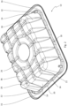
- Fig. 1 is an upper perspective view of a container 10 for the packaging of food, such as vacuum packaging or modified atmosphere packaging.
- the container 10 comprises a bottom 12 and upwardly extending side walls 14, which surround the bottom 12 and provides an opening into the container.
- the side walls 14 comprise, at an upper end thereof, a circumferential planar rim 16, which surrounds the opening and creates a surface onto which a top film/sheet (not shown) can be attached.
- a top film/sheet not shown
- the side walls 14 comprise a reinforcing element 18 below the rim 16, said reinforcing element 18 being arranged as a longitudinal reinforcing rib having a wave-shaped configuration such that the junction between the walls and the rim are wave-shaped and hereby arranged non-parallel with the walls.
- the reinforcing element 18 is arranged as part of the side walls 14, and the rim 16 extends from the reinforcing element 18, whereby the inner part of the rim 16 defines a boundary of the wave-shaped pattern of the reinforcing element 18.
- the moment of inertia reference line 42 which is the line around which the moment of inertia is directed, and the line around which the rim 16 will rotate 44 due to an external force.
- the reference line 42 is, due to the wave-shaped configuration of the reinforcing element 18, located through the wave amplitude, i.e. between the wave crests 20 ( fig. 2 ) and the wave throughs 22 ( fig. 2 ), whereby the moment of inertia is established through a non-straight construction part, which renders the rim 16 more stable.
- the side walls 14 and the bottom 12 comprise a pattern of supporting ribs 24, 26, which provides stability to the sidewalls 14 and bottom 12 in general.
- the vertical reinforcing ribs 24 of the side walls 14 extend from below the bottom 12 and in continuation with the bottom ribs 26, which feature provides stability of the container 10 at the junction between the bottom 12 and the side walls 14.
- the bottom 12 of the container 10 is arranged with a planar center part, also referred to as suction part 30, which provides the possibility of lifting the container by suction via a suction cup during the production line.
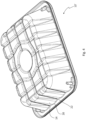
- Fig. 2 is a lower perspective view of the container 10.
- the wave-shaped reinforcing element 18 is more clearly shown in figure 2 , where it is evident that the reinforcing element 18 is arranged towards the outside of the container 10, such that the wave crests 20 raise from the outer surface of the side walls 14, with a distance 34.
- the wave throughs 22 are planar with the outer surface of the side walls 14, but in a preferred embodiment, also the wave throughs raise from the outer surface of the side walls 14, which increases the effect of the reinforcing element 18.
- the vertical reinforcing ribs 24 are shown arranged independently in relation to the reinforcing element 18.
- the bottom 12 of the container 10 is provided with a pattern of bottom supporting ribs 26, hereby dividing the bottom surface into a number of bottom elements, which in the illustrated embodiment include four corner elements 28 and a number of main surface elements 36.
- the main surface elements 36 include all the bottom elements except the corner elements 28.
- the container comprises a number of denesters 32.
- the denesters 32 arranges the containers 10, when being stacked, with a distance between the stacked containers.
- the denesters are arranged below and in contact with the reinforcing element 18 at the side wall 14 corners, which besides the denester effect, also provides an additional stability to the corner part of the rim 16.
- the denesters 32 may in an alternative embodiment be provided on the bottom surface of the corner posts 28. Besides the denester function, this embodiment establishes a distance between the main surface elements 36 and a support surface, upon which the container 10 is placed. This has the technical effect, as previously disclosed, that the stability of the container 10 on a production line is maintained and the containers are prevented from rotating.
- Fig. 3 and Fig. 4 are upper and lower perspective views, respectively, of a container 10' without the reinforcing element 18.
- the walls 14 are at the junction between the walls 14 and the rim 16 arranged with a wave-shaped configuration, such that the junction is arranged non-parallel in relation to the longitudinal direction of said rim part 16.
- Fig. 5A is a side view of the container 10, showing the same technical features as described in relation to figures 1 and 2 .
- Fig. 5B is a blow-up of a corner part of the container 10.
- the figure illustrates a corner post 28 and a main surface element 36 next to the corner post 28.
- the corner post 28 projects downwards in relation to a plane defined by the main surface element with a predefined distance, also called the bottom height 38.
- the arranging of the main part of the bottom 12 at a bottom height 38 has det above-defined technical effect that the stability of the container 10 on the production line is maintained and the containers 10 are prevented from rotating.
- the bottom height 38 should be sufficient to arrange the main part of the bottom 12 at a distance from a support surface and at the same time not contribute to an unnecessary increase of the overall height of the container, which as previously disclosed, is undesirable. Keeping the raised main surface at a minimum arranges the container with a minimum height and has the further advantage that, when filling the container with the desired content, the weight of such content will force the central part of the bottom (the belly) in contact with the below surface, hereby increasing the contact surface of the container, which generates increased friction therewith.
- Fig. 5C-5D are blow-ups of a surface of the bottom 12 of the container 10.
- the figures illustrate a corner post 28 and a main surface element 36 next to the corner post 28.
- the corner post 28 comprises a surface having greater roughness compared to the surface of the main surface element 36. This feature can be used in combination with the embodiment disclosed in fig 3B or in an embodiment where corner posts 28 and main surface elements 36 have substantially the same height.
- Arranging the corner posts 28 and/or a number of main surface elements 36 with a surface having increased roughness increases the bottom friction of the container and avoids unintentional rotation on the production line.
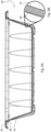
- Fig. 6A is a cross-sectional view of the container 10 along the line A-A in Fig. 1 .
- the container 10 comprises the same features as disclosed in relation to figures 1-2 and 4-5D .
- Fig. 6B is a blow-up of the cross-sectional view according to fig. 6A .
- the figure shows a side wall 14 where a barrier film 40 is arranged on the inner surface of the wall.
- the container 10 made from permeable and moist-sensitive pulp, is not suitable to be used in combination with "wet" foods such as fresh meat, and for that reason it is preferred to use a barrier film 40 arranged on the inner side walls 14 and the inner surface of the bottom 12, in order to render the container moist-resistant and gas tight/diffusion tight, so that it can be used to contain fresh meat and further to allow a hermetic sealing of the content by use of a top film (not shown) for the purpose of food preservation.
Landscapes
- Engineering & Computer Science (AREA)
- Mechanical Engineering (AREA)
- Ceramic Engineering (AREA)
- Life Sciences & Earth Sciences (AREA)
- Biodiversity & Conservation Biology (AREA)
- Containers Having Bodies Formed In One Piece (AREA)
Claims (19)
- Récipient (10, 10') pour l'emballage d'aliments, tel qu'un emballage sous vide ou un emballage sous atmosphère modifiée, ledit récipient (10, 10') comprenant une partie inférieure (12) définissant un plan inférieur, et des parois latérales se prolongeant vers le haut (14) entourant ladite partie inférieure (12), et ayant des surfaces de paroi intérieures tournées vers l'intérieur dudit récipient (10, 10') et des surfaces de paroi extérieures tournées vers l'extérieur dudit récipient (10, 10'), lesdites parois latérales se prolongeant vers le haut (14) comprenant, à une extrémité supérieure de celles-ci, une partie de rebord longitudinale circonférentielle (16) ayant une surface principale plane sensiblement parallèle audit plan inférieur,ledit récipient (10, 10') étant agencé avec une jonction entre lesdites parois latérales (14) et ladite partie de rebord (16),caractérisé en ce,qu'au moins 50 % de ladite jonction est non parallèle par rapport à une direction longitudinale de ladite partie de rebord (16), pour générer un moment d'inertie accru de ladite partie de rebord (16) le long de la direction longitudinale de celle-ci.
- Récipient (10, 10') selon la revendication 1, dans lequel ledit récipient (10, 10') est fabriqué à partir de pâte de fibres.
- Récipient (10, 10') selon l'une quelconque des revendications 1 à 2, dans lequel ladite jonction comprend une ligne non droite.
- Récipient (10, 10') selon l'une quelconque des revendications 1 à 3, dans lequel ladite jonction est en forme d'onde et comprend un certain nombre d'ondes ayant une longueur d'onde avec une direction sensiblement parallèle à ladite partie de bord.
- Récipient (10, 10') selon l'une quelconque des revendications 1 à 4, dans lequel lesdites parois latérales se prolongeant vers le haut (14) comprennent également un élément de renforcement (18) sous ladite partie de rebord longitudinale (16), ladite jonction étant disposée entre ledit élément de renforcement (18) et ladite partie de rebord (16).
- Récipient (10, 10') selon la revendication 5, dans lequel ledit élément de renforcement (18) est une nervure de renforcement longitudinale se prolongeant sensiblement parallèlement à ladite partie de rebord (16) et en-dessous de celle-ci.
- Récipient (10, 10') selon la revendication 6, dans lequel ladite nervure de renforcement longitudinale est en forme d'onde et comprend un certain nombre d'ondes ayant une longueur d'onde avec une direction qui est sensiblement parallèle à ladite partie de rebord (16).
- Récipient (10, 10') selon l'une quelconque des revendications 6 à 7, dans lequel une partie desdites parois latérales se prolongeant vers le haut (14) définit ladite nervure, ladite nervure ayant une épaisseur de matériau sensiblement égale à une épaisseur d'une partie restante desdites parois latérales se prolongeant vers le haut (14).
- Récipient (10, 10') selon la revendication 7, dans lequel ladite nervure en forme ondulée comprend un certain nombre de crêtes (20) et de points traversants (22) surélevés par rapport aux plans desdites surfaces de paroi extérieures.
- Récipient (10, 10') selon l'une quelconque des revendications précédentes, dans lequel lesdites parois latérales se prolongeant vers le haut (14) comprennent un certain nombre de nervures de renforcement sensiblement verticales (24) se prolongeant à partir dudit fond (12) pour générer un moment d'inertie accru desdites parois latérales se prolongeant vers le haut (14) le long d'une direction parallèle à ladite direction longitudinale de ladite partie de bord longitudinale (16), respectivement.
- Récipient (10, 10') selon la revendication 10, dans lequel lesdites nervures de renforcement sensiblement verticales (24) sont disposées indépendamment par rapport à ladite jonction.
- Récipient (10, 10') selon l'une quelconque des revendications précédentes, ledit récipient (10, 10') comprenant une barrière (40) pour rendre le récipient (10, 10') étanche à la diffusion.
- Récipient (10, 10') selon la revendication 12, dans lequel ladite barrière (40) est disposée sur lesdites surfaces de paroi intérieure, une surface intérieure dudit fond (12) et sur ladite surface principale plane dudit rebord (16).
- Récipient (10, 10') selon les revendications 12 ou 13, dans lequel ladite barrière (40) a une épaisseur comprise entre 20 et 125 µm, de préférence entre 20 et 80 µm, et mieux encore entre 20 et 60 µm.
- Récipient (10, 10') selon les revendications 12 à 14, dans lequel ladite barrière (40) peut être décollée desdites surfaces de fond et de paroi.
- Récipient (10, 10') selon l'une quelconque des revendications précédentes, ledit récipient (10, 10') comprenant une surface principale inférieure de ladite partie inférieure (12), qui, lorsque ledit récipient (10, 10') est placé sur une surface plane, est surélevée par rapport à la surface inférieure restante de ladite partie inférieure (12).
- Récipient (10, 10') selon la revendication 16, dans lequel ladite surface inférieure dudit récipient (10, 10'), sur les coins de celui-ci, comprend des éléments en saillie pour rendre ladite surface principale inférieure surélevée par rapport à ladite surface plane.
- Récipient (10, 10') selon l'une quelconque des revendications précédentes, dans lequel une surface inférieure de ladite partie inférieure (12) comprend une partie ayant une structure de surface rugueuse par rapport à la partie restante de ladite surface inférieure.
- Récipient (10, 10') selon l'une quelconque des revendications précédentes, ledit récipient (10, 10') comprenant un dépileur (32).
Applications Claiming Priority (2)
| Application Number | Priority Date | Filing Date | Title |
|---|---|---|---|
| EP21156835.7A EP4043357A1 (fr) | 2021-02-12 | 2021-02-12 | Récipient alimentaire en pulpe de fibres |
| PCT/EP2021/080558 WO2022171319A1 (fr) | 2021-02-12 | 2021-11-03 | Récipient alimentaire en pâte de fibres |
Publications (3)
| Publication Number | Publication Date |
|---|---|
| EP4274785A1 EP4274785A1 (fr) | 2023-11-15 |
| EP4274785C0 EP4274785C0 (fr) | 2025-01-29 |
| EP4274785B1 true EP4274785B1 (fr) | 2025-01-29 |
Family
ID=74673009
Family Applications (2)
| Application Number | Title | Priority Date | Filing Date |
|---|---|---|---|
| EP21156835.7A Withdrawn EP4043357A1 (fr) | 2021-02-12 | 2021-02-12 | Récipient alimentaire en pulpe de fibres |
| EP21802720.9A Active EP4274785B1 (fr) | 2021-02-12 | 2021-11-03 | Récipient alimentaire en pulpe de fibres |
Family Applications Before (1)
| Application Number | Title | Priority Date | Filing Date |
|---|---|---|---|
| EP21156835.7A Withdrawn EP4043357A1 (fr) | 2021-02-12 | 2021-02-12 | Récipient alimentaire en pulpe de fibres |
Country Status (4)
| Country | Link |
|---|---|
| US (1) | US20240150066A1 (fr) |
| EP (2) | EP4043357A1 (fr) |
| CA (1) | CA3205952A1 (fr) |
| WO (1) | WO2022171319A1 (fr) |
Families Citing this family (8)
| Publication number | Priority date | Publication date | Assignee | Title |
|---|---|---|---|---|
| USD1119574S1 (en) * | 2022-12-16 | 2026-03-24 | Brødrene Hartmann A/S | Meat tray/packaging for foodstuffs |
| USD1119573S1 (en) * | 2022-12-16 | 2026-03-24 | Brødrene Hartmann A/S | Meat tray/packaging for foodstuffs |
| USD1119571S1 (en) * | 2022-12-16 | 2026-03-24 | Brødrene Hartmann A/S | Meat tray/packaging for foodstuffs |
| USD1119570S1 (en) * | 2022-12-16 | 2026-03-24 | Brødrene Hartmann A/S | Meat tray/packaging for foodstuffs |
| USD1119572S1 (en) * | 2022-12-16 | 2026-03-24 | Brødrene Hartmann A/S | Meat tray/packaging for foodstuffs |
| USD1122095S1 (en) * | 2022-12-16 | 2026-04-14 | Brødrene Hartmann A/S | Meat tray/packaging for foodstuffs |
| AU2024228557A1 (en) * | 2023-02-27 | 2025-09-04 | Eastman Chemical Company | Cellulose ester tray |
| SE547802C2 (en) * | 2023-12-07 | 2025-12-02 | Stora Enso Oyj | A molded three-dimensional packaging product and a method for making the same |
Citations (4)
| Publication number | Priority date | Publication date | Assignee | Title |
|---|---|---|---|---|
| US4660734A (en) * | 1986-04-04 | 1987-04-28 | The Vollrath Company | Steam table pan |
| US5628427A (en) * | 1995-06-07 | 1997-05-13 | Packaging Corporation Of America | Disposable cooking pan |
| EP1160175A1 (fr) * | 2000-05-31 | 2001-12-05 | Brodrene Hartmann A/S | Récipient revêtu avec rebord |
| US20200181849A1 (en) * | 2016-09-14 | 2020-06-11 | Oneworld Packaging Sl | Improved pulp disposable tray |
Family Cites Families (10)
| Publication number | Priority date | Publication date | Assignee | Title |
|---|---|---|---|---|
| US4801017A (en) * | 1986-10-17 | 1989-01-31 | Aldo Artusi | Container, particularly for receiving foods |
| DE19729326A1 (de) * | 1997-07-09 | 1999-01-14 | Bp Chemicals Plastec Gmbh | Verpackungsbehälter |
| EP1475314B1 (fr) * | 2003-05-07 | 2005-07-27 | Arta Plast Ab | Récipient avec couvercle |
| DE502005005020D1 (de) * | 2005-02-22 | 2008-09-25 | Arta Plast Ab | Behälter |
| EP2288552B1 (fr) * | 2008-05-08 | 2012-08-15 | Huhtamaki Nederland B.V. | Emballage alimentaire |
| RU2010152350A (ru) * | 2008-05-22 | 2012-06-27 | Крайовак, Инк. (Us) | Газобарьерная и адсорбирующая жидкость емкость для упаковки пищевых продуктов |
| US20160221742A1 (en) * | 2015-02-03 | 2016-08-04 | Frito-Lay North America, Inc. | Heat-able On-the-Go Food Products Apparatus and Method |
| US10428467B2 (en) * | 2016-07-26 | 2019-10-01 | Footprint International, LLC | Methods and apparatus for manufacturing fiber-based meat containers |
| US12037749B2 (en) * | 2016-07-26 | 2024-07-16 | Footprint International, LLC | Acrylate and non-acrylate based chemical compositions for selectively coating fiber-based food containers |
| GB2589532A (en) * | 2018-10-08 | 2021-06-09 | Hpc Healthline Uk Ltd | A recyclable moulded pulp container |
-
2021
- 2021-02-12 EP EP21156835.7A patent/EP4043357A1/fr not_active Withdrawn
- 2021-11-03 US US18/273,587 patent/US20240150066A1/en active Pending
- 2021-11-03 CA CA3205952A patent/CA3205952A1/fr active Pending
- 2021-11-03 WO PCT/EP2021/080558 patent/WO2022171319A1/fr not_active Ceased
- 2021-11-03 EP EP21802720.9A patent/EP4274785B1/fr active Active
Patent Citations (4)
| Publication number | Priority date | Publication date | Assignee | Title |
|---|---|---|---|---|
| US4660734A (en) * | 1986-04-04 | 1987-04-28 | The Vollrath Company | Steam table pan |
| US5628427A (en) * | 1995-06-07 | 1997-05-13 | Packaging Corporation Of America | Disposable cooking pan |
| EP1160175A1 (fr) * | 2000-05-31 | 2001-12-05 | Brodrene Hartmann A/S | Récipient revêtu avec rebord |
| US20200181849A1 (en) * | 2016-09-14 | 2020-06-11 | Oneworld Packaging Sl | Improved pulp disposable tray |
Also Published As
| Publication number | Publication date |
|---|---|
| EP4274785C0 (fr) | 2025-01-29 |
| WO2022171319A1 (fr) | 2022-08-18 |
| CA3205952A1 (fr) | 2022-08-18 |
| EP4043357A1 (fr) | 2022-08-17 |
| EP4274785A1 (fr) | 2023-11-15 |
| US20240150066A1 (en) | 2024-05-09 |
Similar Documents
| Publication | Publication Date | Title |
|---|---|---|
| US20240150066A1 (en) | A food container of fiber pulp | |
| US12103743B2 (en) | Product package and method of manufacturing the same as well as package blank | |
| FI20176011A1 (fi) | Pinottava tuotepakkaus ja menetelmä sen valmistamiseksi sekä tuotepakkausaihio | |
| US20110132791A1 (en) | Packaging unit | |
| US5048716A (en) | Cardboard container with reinforcing slits lined with synthetic material | |
| KR20200017455A (ko) | 식품 제품의 운반 및 보관용 용기 | |
| JP2020512242A5 (fr) | ||
| US3715853A (en) | Boilable bakeable package and method | |
| MX2010012258A (es) | Empaque para alimentos. | |
| RU2583361C2 (ru) | Способ формирования упаковки, упаковка и заготовка упаковки | |
| US10961010B2 (en) | Tray with enhanced rigidity and crush strength | |
| JPH0366214B2 (fr) | ||
| US20190241340A1 (en) | Packaging tray | |
| EP0005368B1 (fr) | Emballage du genre 'blister' et procédé de fabrication d'un tel emballage | |
| BR112023015402B1 (pt) | Contêiner de polpa de fibra para embalagem de alimentos | |
| FI20205419A1 (fi) | Tuotepakkaus ja menetelmä sen valmistamiseksi sekä tuote-pakkausaihio | |
| GB2226543A (en) | Packaging containers | |
| US20240253893A1 (en) | Container, intermediate product, denester and a manufacturing method | |
| RU229202U1 (ru) | Контейнер для упаковки готового продукта | |
| EP4653337A1 (fr) | Récipient sans soudure | |
| WO2024165661A1 (fr) | Pelliplacage sous vide | |
| FI130573B (fi) | Tuotepakkaus ja menetelmä sen valmistamiseksi | |
| FI12983Y1 (fi) | Tuotepakkaus ja tuotepakkausaihio | |
| GB1574145A (en) | Composite lid | |
| HK1261738A1 (en) | Container for transport and storage of food products |
Legal Events
| Date | Code | Title | Description |
|---|---|---|---|
| STAA | Information on the status of an ep patent application or granted ep patent |
Free format text: STATUS: UNKNOWN |
|
| STAA | Information on the status of an ep patent application or granted ep patent |
Free format text: STATUS: THE INTERNATIONAL PUBLICATION HAS BEEN MADE |
|
| PUAI | Public reference made under article 153(3) epc to a published international application that has entered the european phase |
Free format text: ORIGINAL CODE: 0009012 |
|
| STAA | Information on the status of an ep patent application or granted ep patent |
Free format text: STATUS: REQUEST FOR EXAMINATION WAS MADE |
|
| 17P | Request for examination filed |
Effective date: 20230809 |
|
| AK | Designated contracting states |
Kind code of ref document: A1 Designated state(s): AL AT BE BG CH CY CZ DE DK EE ES FI FR GB GR HR HU IE IS IT LI LT LU LV MC MK MT NL NO PL PT RO RS SE SI SK SM TR |
|
| DAV | Request for validation of the european patent (deleted) | ||
| DAX | Request for extension of the european patent (deleted) | ||
| GRAP | Despatch of communication of intention to grant a patent |
Free format text: ORIGINAL CODE: EPIDOSNIGR1 |
|
| STAA | Information on the status of an ep patent application or granted ep patent |
Free format text: STATUS: GRANT OF PATENT IS INTENDED |
|
| INTG | Intention to grant announced |
Effective date: 20240830 |
|
| GRAS | Grant fee paid |
Free format text: ORIGINAL CODE: EPIDOSNIGR3 |
|
| GRAA | (expected) grant |
Free format text: ORIGINAL CODE: 0009210 |
|
| STAA | Information on the status of an ep patent application or granted ep patent |
Free format text: STATUS: THE PATENT HAS BEEN GRANTED |
|
| AK | Designated contracting states |
Kind code of ref document: B1 Designated state(s): AL AT BE BG CH CY CZ DE DK EE ES FI FR GB GR HR HU IE IS IT LI LT LU LV MC MK MT NL NO PL PT RO RS SE SI SK SM TR |
|
| REG | Reference to a national code |
Ref country code: GB Ref legal event code: FG4D |
|
| REG | Reference to a national code |
Ref country code: CH Ref legal event code: EP |
|
| REG | Reference to a national code |
Ref country code: DE Ref legal event code: R096 Ref document number: 602021025532 Country of ref document: DE |
|
| REG | Reference to a national code |
Ref country code: IE Ref legal event code: FG4D |
|
| U01 | Request for unitary effect filed |
Effective date: 20250226 |
|
| U07 | Unitary effect registered |
Designated state(s): AT BE BG DE DK EE FI FR IT LT LU LV MT NL PT RO SE SI Effective date: 20250304 |
|
| PG25 | Lapsed in a contracting state [announced via postgrant information from national office to epo] |
Ref country code: RS Free format text: LAPSE BECAUSE OF FAILURE TO SUBMIT A TRANSLATION OF THE DESCRIPTION OR TO PAY THE FEE WITHIN THE PRESCRIBED TIME-LIMIT Effective date: 20250429 |
|
| PG25 | Lapsed in a contracting state [announced via postgrant information from national office to epo] |
Ref country code: PL Free format text: LAPSE BECAUSE OF FAILURE TO SUBMIT A TRANSLATION OF THE DESCRIPTION OR TO PAY THE FEE WITHIN THE PRESCRIBED TIME-LIMIT Effective date: 20250129 |
|
| PG25 | Lapsed in a contracting state [announced via postgrant information from national office to epo] |
Ref country code: ES Free format text: LAPSE BECAUSE OF FAILURE TO SUBMIT A TRANSLATION OF THE DESCRIPTION OR TO PAY THE FEE WITHIN THE PRESCRIBED TIME-LIMIT Effective date: 20250129 |
|
| PG25 | Lapsed in a contracting state [announced via postgrant information from national office to epo] |
Ref country code: NO Free format text: LAPSE BECAUSE OF FAILURE TO SUBMIT A TRANSLATION OF THE DESCRIPTION OR TO PAY THE FEE WITHIN THE PRESCRIBED TIME-LIMIT Effective date: 20250429 Ref country code: IS Free format text: LAPSE BECAUSE OF FAILURE TO SUBMIT A TRANSLATION OF THE DESCRIPTION OR TO PAY THE FEE WITHIN THE PRESCRIBED TIME-LIMIT Effective date: 20250529 |
|
| PG25 | Lapsed in a contracting state [announced via postgrant information from national office to epo] |
Ref country code: HR Free format text: LAPSE BECAUSE OF FAILURE TO SUBMIT A TRANSLATION OF THE DESCRIPTION OR TO PAY THE FEE WITHIN THE PRESCRIBED TIME-LIMIT Effective date: 20250129 |
|
| PG25 | Lapsed in a contracting state [announced via postgrant information from national office to epo] |
Ref country code: GR Free format text: LAPSE BECAUSE OF FAILURE TO SUBMIT A TRANSLATION OF THE DESCRIPTION OR TO PAY THE FEE WITHIN THE PRESCRIBED TIME-LIMIT Effective date: 20250430 |
|
| PG25 | Lapsed in a contracting state [announced via postgrant information from national office to epo] |
Ref country code: SM Free format text: LAPSE BECAUSE OF FAILURE TO SUBMIT A TRANSLATION OF THE DESCRIPTION OR TO PAY THE FEE WITHIN THE PRESCRIBED TIME-LIMIT Effective date: 20250129 |
|
| PG25 | Lapsed in a contracting state [announced via postgrant information from national office to epo] |
Ref country code: CZ Free format text: LAPSE BECAUSE OF FAILURE TO SUBMIT A TRANSLATION OF THE DESCRIPTION OR TO PAY THE FEE WITHIN THE PRESCRIBED TIME-LIMIT Effective date: 20250129 |
|
| PG25 | Lapsed in a contracting state [announced via postgrant information from national office to epo] |
Ref country code: SK Free format text: LAPSE BECAUSE OF FAILURE TO SUBMIT A TRANSLATION OF THE DESCRIPTION OR TO PAY THE FEE WITHIN THE PRESCRIBED TIME-LIMIT Effective date: 20250129 |
|
| PLBE | No opposition filed within time limit |
Free format text: ORIGINAL CODE: 0009261 |
|
| STAA | Information on the status of an ep patent application or granted ep patent |
Free format text: STATUS: NO OPPOSITION FILED WITHIN TIME LIMIT |
|
| 26N | No opposition filed |
Effective date: 20251030 |
|
| U21 | Renewal fee for the european patent with unitary effect paid with additional fee |
Year of fee payment: 5 Effective date: 20260127 |
|
| PGFP | Annual fee paid to national office [announced via postgrant information from national office to epo] |
Ref country code: GB Payment date: 20260127 Year of fee payment: 5 |
|
| PGFP | Annual fee paid to national office [announced via postgrant information from national office to epo] |
Ref country code: IE Payment date: 20260127 Year of fee payment: 5 |