EP4275534A1 - Chaussure d'escalade - Google Patents
Chaussure d'escalade Download PDFInfo
- Publication number
- EP4275534A1 EP4275534A1 EP23172194.5A EP23172194A EP4275534A1 EP 4275534 A1 EP4275534 A1 EP 4275534A1 EP 23172194 A EP23172194 A EP 23172194A EP 4275534 A1 EP4275534 A1 EP 4275534A1
- Authority
- EP
- European Patent Office
- Prior art keywords
- shoe
- head
- loop
- plate
- climbing
- Prior art date
- Legal status (The legal status is an assumption and is not a legal conclusion. Google has not performed a legal analysis and makes no representation as to the accuracy of the status listed.)
- Withdrawn
Links
Images
Classifications
-
- A—HUMAN NECESSITIES
- A43—FOOTWEAR
- A43B—CHARACTERISTIC FEATURES OF FOOTWEAR; PARTS OF FOOTWEAR
- A43B5/00—Footwear for sporting purposes
- A43B5/002—Mountain boots or shoes
- A43B5/003—Mountain boots or shoes for free climbing
-
- A—HUMAN NECESSITIES
- A43—FOOTWEAR
- A43B—CHARACTERISTIC FEATURES OF FOOTWEAR; PARTS OF FOOTWEAR
- A43B11/00—Footwear with arrangements to facilitate putting-on or removing, e.g. with straps
-
- A—HUMAN NECESSITIES
- A43—FOOTWEAR
- A43B—CHARACTERISTIC FEATURES OF FOOTWEAR; PARTS OF FOOTWEAR
- A43B23/00—Uppers; Boot legs; Stiffeners; Other single parts of footwear
- A43B23/26—Tongues for shoes
-
- A—HUMAN NECESSITIES
- A43—FOOTWEAR
- A43C—FASTENINGS OR ATTACHMENTS OF FOOTWEAR; LACES IN GENERAL
- A43C1/00—Shoe lacing fastenings
- A43C1/04—Shoe lacing fastenings with rings or loops
-
- A—HUMAN NECESSITIES
- A43—FOOTWEAR
- A43C—FASTENINGS OR ATTACHMENTS OF FOOTWEAR; LACES IN GENERAL
- A43C11/00—Other fastenings specially adapted for shoes
- A43C11/004—Fastenings fixed along the upper edges of the uppers
-
- A—HUMAN NECESSITIES
- A43—FOOTWEAR
- A43C—FASTENINGS OR ATTACHMENTS OF FOOTWEAR; LACES IN GENERAL
- A43C11/00—Other fastenings specially adapted for shoes
- A43C11/008—Combined fastenings, e.g. to accelerate undoing or fastening
-
- A—HUMAN NECESSITIES
- A43—FOOTWEAR
- A43C—FASTENINGS OR ATTACHMENTS OF FOOTWEAR; LACES IN GENERAL
- A43C11/00—Other fastenings specially adapted for shoes
- A43C11/14—Clamp fastenings, e.g. strap fastenings; Clamp-buckle fastenings; Fastenings with toggle levers
- A43C11/1493—Strap fastenings having hook and loop-type fastening elements
Definitions
- the present invention relates to a climbing shoe.
- the currently most widespread climbing shoes comprise: a shoe-upper made of leather and/or fabric which is substantially sock-shaped so as to accommodate and cover the user's foot, comprising the sole of the foot; a front tensioning band with a ribbon-like structure, which is made of elastomeric material having high elasticity, is substantially U-bent, and is firmly fixed to the front part of the shoe-upper by gluing, so as to cover the tip and the inner and outer sides of the front part of the shoe-upper; a rear tensioning band with a ribbon-like structure, which is made of elastomeric material having high elasticity, is substantially U-bent, and is fixed by gluing to the rear part of the shoe-upper so as to cover the zone above the heel, and then extend obliquely along the two lateral sides of the shoe-upper up to reach and join the front tensioning band; and a bottom sole, which is made of a soft and flexible polymeric material with high friction coefficient and substantially inextensible, and is fixed by
- the front and rear tensioning bands are furthermore suitably pretensioned so as to embrace and tighten the shoe-upper on the user's foot.
- the top part of the shoe-upper is usually tightened on the instep of the user's foot by means of a traditional closing lace that pulls two longitudinal and opposite edges of the front-top part of the shoe-upper toward each other.
- a traditional closing lace that pulls two longitudinal and opposite edges of the front-top part of the shoe-upper toward each other.
- the two longitudinal edges of the shoe-upper can be pulled toward each other by a pair of hook-and-loop transversal straps, each of which has an end fixed by stitching to a first longitudinal edge of the shoe-upper, is U-folded on itself after engaging a return eyelet located on the second longitudinal edge of the shoe-upper, and is finally held in position by a Velcro locking system located in the overlapping zone.
- hook-and-loop closing straps are very much appreciated by users because their tensioning is extremely simple and quick, even if the Velcro locking system tends to loosen rather quickly and unfortunately requires a frequent repositioning of the straps, with the problems of use that this entail.
- Aim of the present invention is to provide a closing system of the front-top part of the shoe-upper that can overcome the above-described drawbacks, and is moreover more versatile than the ones currently in use.
- a climbing shoe as defined in claim 1 and preferably, though not necessarily, in any one of the dependent claims.
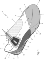
- reference numeral 1 denotes, as a whole, a climbing shoe which may be particularly advantageously used for climbing rock walls classified as grade III or higher.
- the climbing shoe 1 firstly comprises: a shoe-upper 2 preferably made of leather and/or fabric, which is substantially sock-shaped so as to accommodate and completely envelop the user's foot, the sole of the foot included; and a sole 3 which is made of a soft and flexible polymeric material, with a high friction coefficient and preferably also substantially inextensible, and is firmly fixed to the bottom 4 of the shoe-upper 2 preferably by gluing, so as to cover at least the front part of the bottom 4 of the shoe-upper 2.
- the bottom 4 of shoe-upper i.e. the piece of the shoe-upper 2 that covers the sole of the user's foot
- a front section 4a that conventionally is located immediately beneath the phalangeal region of the sole of the user's foot
- a central section 4b that conventionally is located immediately beneath the metatarsal region of the sole of the user's foot, i.e. below the plantar arch
- a rear section 4c that conventionally is located immediately beneath the astragalus-calcaneus region of the sole of the user's foot.
- the sole 3 is preferably shaped/dimensioned so as to substantially entirely cover the bottom 4 of the shoe-upper 2, optionally also rising up along the rear part of the shoe-upper 2 so as to also cover the heel of the user's foot.
- the sole 3 is moreover made of a polymeric material having a hardness (UNI 4916) preferably less than 80 ShoreA and advantageously ranging between 50 and 75 ShoreA.
- a hardness UNI 4916
- the front sole 3 is preferably made of a soft and flexible polymeric material, such as for example the blend XS GRIP 2 produced by the Italian company VIBRAM S.P.A..
- the sole 3 may be shaped/dimensioned so as to substantially entirely cover only the front section 4a of the bottom 4 of shoe-upper 2 and advantageously also a limited part of the adjacent central section 4b.
- the sole 3 may be shaped/dimensioned so as to leave uncovered the rear section 4c of the bottom 4 of the shoe-upper 2.
- the climbing shoe 1 comprises also at least one and more conveniently a plurality of elastic tensioning bands, which are made of elastomeric material with high elasticity and are firmly fixed to the shoe-upper 2, or rather to the outer surface of the shoe-upper 2, preferably seamlessly and preferably by gluing, so as to embrace and tighten the shoe-upper 2 on the user's foot.
- the tensioning bands are furthermore pretensioned.
- each tensioning band has an elastically-deformable monolithic structure and has an elastic modulus (Young modulus) considerably lower than that of the sole 3.
- the tensioning bands advantageously have an elastic modulus 2-10 times lower than that of the sole 3.
- the elastomeric material forming at least one and more conveniently each tensioning band preferably has a hardness (UNI 4916) greater than that of the polymeric material forming the sole 3.
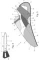
- the climbing shoe 1 is preferably provided with a rear tensioning band 5 having a ribbon-like monolithic structure, which is U-bent and is located astride the rear part of the shoe-upper 2, so that its curved central segment 5a covers the zone of the shoe-upper 2 above the heel of the user's foot, and that its two oblong lateral segments 5b extend obliquely along the inner and outer lateral sides of the shoe-upper 2, up to reach the bottom 4 preferably substantially at the central section 4b thereof.
- a rear tensioning band 5 having a ribbon-like monolithic structure, which is U-bent and is located astride the rear part of the shoe-upper 2, so that its curved central segment 5a covers the zone of the shoe-upper 2 above the heel of the user's foot, and that its two oblong lateral segments 5b extend obliquely along the inner and outer lateral sides of the shoe-upper 2, up to reach the bottom 4 preferably substantially at the central section 4b thereof.
- the two ends of rear tensioning band 5 moreover extend/prolong on the bottom 4 of shoe-upper 2 toward each other, underneath the sole 3.
- the two ends of the rear tensioning band 5 extend/prolong on the bottom 4 of shoe-upper 2 within the central section 4b of the bottom 4 and optionally also within the front section 4a and/or the rear portion 4c of the bottom 4.
- the rear tensioning band 5 is preferably also pretensioned, and is preferably firmly fixed to the outer surface of the shoe-upper 2 substantially seamlessly by gluing.
- the climbing shoe 1 is preferably also provided with a central tensioning band 6 with a ribbon-like monolithic structure, separate and distinct from the rear tensioning band 5, which is substantially V-shaped, has the vertex or central segment located on the bottom 4 of shoe-upper 2, underneath the sole 3 at the front section 4a of the bottom 4, and has the two oblong lateral segments 6b which extend obliquely toward the rear part of the shoe-upper 2, along the inner and outer lateral sides of the shoe-upper 2, up to reach and firmly join the rear tensioning band 5 preferably along the two oblong lateral segments 5b of the latter.
- a central tensioning band 6 with a ribbon-like monolithic structure, separate and distinct from the rear tensioning band 5, which is substantially V-shaped, has the vertex or central segment located on the bottom 4 of shoe-upper 2, underneath the sole 3 at the front section 4a of the bottom 4, and has the two oblong lateral segments 6b which extend obliquely toward the rear part of the shoe-upper 2, along the inner and outer
- the central tensioning band 6 is preferably pretensioned, and is preferably firmly fixed to the outer surface of the shoe-upper 2 substantially seamlessly by gluing.
- the central tensioning band 6 is moreover dimensioned so as to bend downward the tip of the user's foot in a banana-like manner.
- the central tensioning band 6 withstands the straightening of the tip of the user's foot.
- the climbing shoe 1 is preferably also provided with a front tensioning band 7 having a ribbon-like monolithic structure, separate and distinct from the tensioning bands 5 and 6, which is U-bent and is located astride the ogival front part of the shoe-upper 2, so that its curved central segment 7a covers the tip of the shoe-upper 2, and that its two oblong lateral segments 7b extend along the inner and outer lateral sides of the shoe-upper 2, remaining contiguous to the sole 3, preferably up to reach and overlap the central tensioning band 6 along the two oblong lateral segments 6b of the latter.
- a front tensioning band 7 having a ribbon-like monolithic structure, separate and distinct from the tensioning bands 5 and 6, which is U-bent and is located astride the ogival front part of the shoe-upper 2, so that its curved central segment 7a covers the tip of the shoe-upper 2, and that its two oblong lateral segments 7b extend along the inner and outer lateral sides of the shoe-upper 2, remaining contig
- the front tensioning band 7 is furthermore shaped so as to also extend on the bottom 4 of the shoe-upper 2 underneath the sole 3, for partially covering the front section 4a and optionally also the central section 4b of the bottom 4, preferably overlapping the central tensioning band 6 in the mutual overlapping zones.
- the front tensioning band 7 is moreover provided with a lateral flap 7c which extends on the front-top part of the shoe-upper 2 to cover and protect the toes of the user's foot, and seamlessly joins the curved central segment 7a.
- the front tensioning band 7 is preferably pretensioned, and is preferably firmly fixed to the outer surface of the shoe-upper 2 substantially seamlessly by gluing.
- the top part of the shoe-upper 2 is preferably moreover provided with an oblong-shaped elasticized portion 8, which extends from the top opening 9 of shoe-upper 2 toward the tip, while remaining substantially astride the midplane of the footwear, so as to cover the instep of the user's foot.
- the climbing shoe 1 is additionally provided with a manually- operated and adjusted closing device 10, which is arranged astride and grazing the top part of the shoe-upper 2, or rather astride and grazing the elasticized portion 8, and is adapted to tighten the top part of the shoe-upper 2 on the user's foot, so as to lock/hold the foot inside the footwear.
- a manually- operated and adjusted closing device 10 which is arranged astride and grazing the top part of the shoe-upper 2, or rather astride and grazing the elasticized portion 8, and is adapted to tighten the top part of the shoe-upper 2 on the user's foot, so as to lock/hold the foot inside the footwear.
- the closing device 10 includes a transversal locking strap 11, which extends like a bridge between the two lateral sides of shoe-upper 2, astride and grazing the top part of the shoe-upper 2, or rather astride and grazing the elasticized portion 8, transversally to the midplane of the footwear, and is adapted to pull the two lateral sides of the shoe-upper 2 toward each other, so as to lock/hold the foot inside the footwear.
- a transversal locking strap 11 which extends like a bridge between the two lateral sides of shoe-upper 2, astride and grazing the top part of the shoe-upper 2, or rather astride and grazing the elasticized portion 8, transversally to the midplane of the footwear, and is adapted to pull the two lateral sides of the shoe-upper 2 toward each other, so as to lock/hold the foot inside the footwear.
- transversal locking strap 11 is coupled/attached in an easily removable manner both to the inner lateral side and to the outer lateral side of the shoe-upper 2, so as to be completely detachable from the shoe-upper 2.
- transversal locking strap 11 is completely separate and distinct from the shoe-upper 2.
- the closing device 10 in particular comprises: a first loop 12 which is located on the inner lateral side of the shoe-upper 2, preferably close to the elasticized portion 8 and/or the top opening 9; a flat anchoring flap or insert 13, which is located on the outer lateral side of the shoe-upper 2, preferably close to the elasticized portion 8 and/or the top opening 9, and is provided, on the exposed face, with a first Velcro surface structure; and preferably also a second loop 14 which is located on the outer lateral side of the shoe-upper 2, immediately above the anchoring flap/insert 13.
- the loop 12 and the anchoring flap/insert 13 are moreover located on the inner and outer lateral sides, respectively, of the shoe-upper 2 in a substantially specular position with respect to the midplane of the footwear, advantageously on opposite sides of elasticized portion 8.
- the locking strap 11 in turn, has a flexible and preferably also substantially inextensible structure, and is couplable in an easily removable manner both to the loop 12 and to the anchoring flap/insert 13, and optionally also to the loop 14.
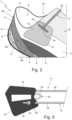
- the transversal locking strap 11 comprises: a plate-like head 15 preferably with a semi-rigid structure, which has, on at least one of the two major faces, a second Velcro surface structure; and a flexible cord 16 with a substantially inextensible structure, which has the two ends firmly fixed to the plate-like head 15, preferably on the sidewall of the head, and is dimensioned so as to form a large, substantially U-shaped bight or eye 17, which has a nominal length H, preferably ranging between 5 and 30 cm (centimetres).
- the Velcro surface structure present on at least one of the two major faces of the plate-like head 15 is moreover complementary to that of the anchoring flap or insert 13, so that the plate-like head 15 can hook/attach firmly, though in an easily removable and adjustable manner, onto the anchoring flap or insert 13.
- the bight or eye 17 formed by the flexible cord 16 is adapted to be threaded into and/or knotted to the loop 12 and optionally also into/to the loop 14.
- the plate-like head 15 is preferably shaped and dimensioned so as not to be able to pass through the loop 12 and optionally also the loop 14, and is preferably provided with a semi-rigid foldable structure, so as to be able to pass through the loop 12 and optionally also the loop 14 in a folded configuration.
- the plate-like head 15 has an elastically deformable semi-rigid structure and remains stably in a flattened/unfolded configuration, but can be book-folded on itself so as to temporarily assume a folded configuration.
- the plate-like head 15 manages to pass through the loop 12, whereas in the flattened/unfolded configuration, the plate-like head 15 does not manage to pass through the loop 12.
- the plate-like head 15 moreover manages to pass through the loop 14.
- the maximum width of the plate-like head 15 in the flattened/unfolded configuration is greater than the nominal width of the loop 12 and preferably also of the loop 14.
- the maximum width of the plate-like head 15 in the folded configuration is less than the nominal width of loop 12 and preferably also of that of loop 14.
- the plate-like head 15 is preferably substantially polygonal in shape, and the two ends of the flexible cord 16 are preferably firmly fixed to the plate-like head 15 spaced apart from each other, advantageously on a same side of the polygon or on two preferably, though not necessarily, consecutive sides of the polygon.
- the plate-like head 15 is furthermore also provided with a small supplementary loop 18, which is selectively engageable by the bight 17 formed by the flexible cord 16.
- the supplementary loop 18 is moreover made up of a second flexible cord 19 with a substantially inextensible structure, separate and distinct from the flexible cord 16, which has the two ends firmly fixed to the plate-like head 15, preferably on the sidewall of the head and preferably between the two ends of the flexible cord 16, and is dimensioned so as to form a second substantially U-shaped bight, which has a length less than that of the bight 17 and can be engaged, in case of need, by the bight 17 formed by the flexible cord 16.
- the loop 12 is preferably made up of a small cord with a flexible and substantially inextensible structure, which extends grazing the shoe-upper 2, close to the edge of the elasticized portion 8, and has the two ends firmly fixed to the shoe-upper 2 advantageously by stitching and/or gluing.
- the anchoring flap or insert 13 is preferably made up of a Velcro fabric patch, which is located on the outer side of the shoe-upper 2, advantageously astride the edge of the elasticized portion 8, and is firmly fixed to the shoe-upper 2 advantageously by stitching and/or gluing.
- the loop 14 is preferably made up of a small cord with a flexible and substantially inextensible structure, which extends grazing the anchoring flap/insert 13, or rather the Velcro fabric patch, close to the edge of the elasticized portion 8, and has the two ends firmly fixed to the anchoring flap/insert 13 and/or to the shoe-upper 2 advantageously by stitching and/or gluing.
- the plate-like head 15 is preferably substantially quadrilateral in shape, and more specifically approximately trapezoidal in shape, and is preferably made of plastic material.
- the two ends of flexible cord 16, and optionally also the two ends of flexible cord 19, are moreover embedded in the body of plate-like head 15.
- the plate-like head 15 may also be made of leather or other similar material.
- the flexible cord 16 in turn, has a total length preferably ranging between 30 and 40 cm (centimetres), whereas the flexible cord 19 has a total length preferably ranging between 3 and 4 cm (centimetres)
- the transversal locking strap 11 has the distal end of the bight 17 fixed to the loop 14 preferably by means of a Cow hitch, the central section of the bight 17 threaded into the loop 12 in free slidable manner, and the plate-like head 15 overlapped and attached to the anchoring flap/insert 13.
- the transversal locking strap 11 has the distal end of the bight 17 fixed to the supplementary loop 18 of the plate-like head 15 preferably by means of a Cow hitch, the central section of the bight 17 threaded into the loop 12 in free slidable manner, and the plate-like head 15 overlapped and attached to the anchoring flap/insert 13.
- the plate-like head 15 and the anchoring flap/insert 13 have a much wider Velcro part with respect to the one present in the traditional hook-and-loop straps, hence the locking strap 11 guarantees a better traction resistance.
- the locking strap 11 can be replaced and/or adapted to the user's needs with extreme quickness, with the ensuing greater fitting comfort.
- the length H, of bight 17, in fact, can be easily varied, or rather reduced, by changing configuration and/or by making one or more knots directly on the flexible cord 16.
- the locking strap 11 better adapts to the morphology of the instep of the user's foot, with the ensuing greater fitting comfort.
- the bight formed by the flexible cord 19 may have a length such that it can be knotted to the loop 12 additionally or alternatively to the bight 17 formed by the flexible cord 16.
- closure device 10 could comprise a pair of loops 12 which are located on the inner lateral side of the shoe-upper 2, preferably close to the elasticized portion 8 and/or the top opening.
- the locking strap 11, moreover, may engage one or both loops 12.
- the loop 12 may be located on the outer lateral side of the shoe-upper 2, whereas the anchoring flap or insert 13 may be located on the inner lateral side of the shoe-upper 2.
- one of the two ends of the flexible cord 16 may be fixed to the plate-like head 15 in a manually adjustable manner, so as to allow the user to adjust at pleasure the total length of the flexible cord 16 and thus the length f of the bight 17.
- the plate-like head 15 is preferably moreover provided with a small U-bolt fairlead 20, which is adapted to be engaged in a pass-through and free slidable manner by the flexible cord 16.
- the flexible cord 16 has, downstream of the U-bolt fairlead 20, a large stop knot 21 (for example a figure-of-eight knot) capable of preventing the slipping away of the flexible cord 16 from the U-bolt, and thus from the plate-like head 15.
- a large stop knot 21 for example a figure-of-eight knot
- the position of the stop knot 21 on the flexible cord 16 determines the length H, of the bight 17 and can be varied at pleasure by the user of the climbing shoe 1 depending on his/her needs.
- the U-bolt fairlead 20 can be replaced by an eyelet, a through hole, a small cable choker or the like.
Landscapes
- Health & Medical Sciences (AREA)
- General Health & Medical Sciences (AREA)
- Physical Education & Sports Medicine (AREA)
- Footwear And Its Accessory, Manufacturing Method And Apparatuses (AREA)
Applications Claiming Priority (1)
| Application Number | Priority Date | Filing Date | Title |
|---|---|---|---|
| IT102022000009599A IT202200009599A1 (it) | 2022-05-10 | 2022-05-10 | Scarpa da arrampicata |
Publications (1)
| Publication Number | Publication Date |
|---|---|
| EP4275534A1 true EP4275534A1 (fr) | 2023-11-15 |
Family
ID=82943256
Family Applications (1)
| Application Number | Title | Priority Date | Filing Date |
|---|---|---|---|
| EP23172194.5A Withdrawn EP4275534A1 (fr) | 2022-05-10 | 2023-05-09 | Chaussure d'escalade |
Country Status (3)
| Country | Link |
|---|---|
| US (1) | US12336595B2 (fr) |
| EP (1) | EP4275534A1 (fr) |
| IT (1) | IT202200009599A1 (fr) |
Citations (5)
| Publication number | Priority date | Publication date | Assignee | Title |
|---|---|---|---|---|
| JPH10179210A (ja) * | 1996-12-19 | 1998-07-07 | Achilles Corp | 新規な緊締部品を備えた靴 |
| US20040078999A1 (en) * | 2001-09-14 | 2004-04-29 | Freed Anna B. | Lacing system |
| US20180295942A1 (en) * | 2017-04-17 | 2018-10-18 | Nike, Inc. | Increased Access Footwear |
| US20190313742A1 (en) * | 2018-04-13 | 2019-10-17 | Nike, Inc. | Footwear fastening system |
| EP3571949A1 (fr) * | 2018-05-23 | 2019-11-27 | Calzaturificio S.C.A.R.P.A. S.p.A. | Chaussure d'escalade |
Family Cites Families (4)
| Publication number | Priority date | Publication date | Assignee | Title |
|---|---|---|---|---|
| US4081916A (en) * | 1977-02-03 | 1978-04-04 | Thomas Salisbury | Quick lace tightener for shoes |
| US5027482A (en) * | 1990-01-24 | 1991-07-02 | Central Dupage Pedorthics, Inc. | Securing device for shoes |
| US5353483A (en) * | 1993-07-06 | 1994-10-11 | Louviere Donald L | Method and apparatus for quickly securing a laced shoe |
| US5970629A (en) * | 1998-05-08 | 1999-10-26 | Montrail, Inc. | Footwear and composite liner for use in such footwear |
-
2022
- 2022-05-10 IT IT102022000009599A patent/IT202200009599A1/it unknown
-
2023
- 2023-05-09 EP EP23172194.5A patent/EP4275534A1/fr not_active Withdrawn
- 2023-05-09 US US18/195,158 patent/US12336595B2/en active Active
Patent Citations (5)
| Publication number | Priority date | Publication date | Assignee | Title |
|---|---|---|---|---|
| JPH10179210A (ja) * | 1996-12-19 | 1998-07-07 | Achilles Corp | 新規な緊締部品を備えた靴 |
| US20040078999A1 (en) * | 2001-09-14 | 2004-04-29 | Freed Anna B. | Lacing system |
| US20180295942A1 (en) * | 2017-04-17 | 2018-10-18 | Nike, Inc. | Increased Access Footwear |
| US20190313742A1 (en) * | 2018-04-13 | 2019-10-17 | Nike, Inc. | Footwear fastening system |
| EP3571949A1 (fr) * | 2018-05-23 | 2019-11-27 | Calzaturificio S.C.A.R.P.A. S.p.A. | Chaussure d'escalade |
Also Published As
| Publication number | Publication date |
|---|---|
| US20240049832A1 (en) | 2024-02-15 |
| US12336595B2 (en) | 2025-06-24 |
| IT202200009599A1 (it) | 2023-11-10 |
Similar Documents
| Publication | Publication Date | Title |
|---|---|---|
| US5467537A (en) | Shoe with adjustable closure system | |
| US7963049B2 (en) | Snowboard boot | |
| US5416987A (en) | Speed closure for footwear | |
| US8006410B2 (en) | Shoe, particularly sport or leisure shoe | |
| US5692319A (en) | Article of footwear with 360° wrap fit closure system | |
| US4366631A (en) | Athletic shoe | |
| US6922917B2 (en) | Shoe tightening system | |
| US5438767A (en) | Sandal having adjustable straps | |
| CA2140577C (fr) | Systeme d'attache de sandale | |
| US20110088283A1 (en) | Footwear with improved tightening of upper | |
| US20130152425A1 (en) | Footwear with improved tightening of upper | |
| JPH0614801A (ja) | トレッキングシューズ用の足固定具 | |
| US8793904B2 (en) | Article of footwear with dual lacing system | |
| US20140276320A1 (en) | Orthosis, system and methods for addressing foot drop | |
| JP7336516B2 (ja) | 靴 | |
| KR101364122B1 (ko) | 발목 조임기능이 내장된 신발 | |
| CA2336319C (fr) | Eperon a fixation par courroies | |
| EP4275534A1 (fr) | Chaussure d'escalade | |
| US7827708B2 (en) | Cycling shoe | |
| CN117837849A (zh) | 具有可定制的系带系统的鞋类 | |
| AU2024347546A1 (en) | Device for closing sports footwear | |
| US20240285032A1 (en) | Lace shoes and tightening method for lace shoes | |
| JP2017006361A (ja) | 靴 | |
| US20100257709A1 (en) | Shoe lace knot retainer | |
| KR200246554Y1 (ko) | 한번의 당김으로 조여지게 되는 신발끈의 결속장치 |
Legal Events
| Date | Code | Title | Description |
|---|---|---|---|
| PUAI | Public reference made under article 153(3) epc to a published international application that has entered the european phase |
Free format text: ORIGINAL CODE: 0009012 |
|
| STAA | Information on the status of an ep patent application or granted ep patent |
Free format text: STATUS: THE APPLICATION HAS BEEN PUBLISHED |
|
| AK | Designated contracting states |
Kind code of ref document: A1 Designated state(s): AL AT BE BG CH CY CZ DE DK EE ES FI FR GB GR HR HU IE IS IT LI LT LU LV MC ME MK MT NL NO PL PT RO RS SE SI SK SM TR |
|
| STAA | Information on the status of an ep patent application or granted ep patent |
Free format text: STATUS: REQUEST FOR EXAMINATION WAS MADE |
|
| 17P | Request for examination filed |
Effective date: 20240510 |
|
| RBV | Designated contracting states (corrected) |
Designated state(s): AL AT BE BG CH CY CZ DE DK EE ES FI FR GB GR HR HU IE IS IT LI LT LU LV MC ME MK MT NL NO PL PT RO RS SE SI SK SM TR |
|
| GRAP | Despatch of communication of intention to grant a patent |
Free format text: ORIGINAL CODE: EPIDOSNIGR1 |
|
| STAA | Information on the status of an ep patent application or granted ep patent |
Free format text: STATUS: GRANT OF PATENT IS INTENDED |
|
| INTG | Intention to grant announced |
Effective date: 20250804 |
|
| STAA | Information on the status of an ep patent application or granted ep patent |
Free format text: STATUS: THE APPLICATION IS DEEMED TO BE WITHDRAWN |
|
| 18D | Application deemed to be withdrawn |
Effective date: 20251205 |