EP4275540A1 - Dispositif de fixation et procédé d'assemblage de lacet - Google Patents
Dispositif de fixation et procédé d'assemblage de lacet Download PDFInfo
- Publication number
- EP4275540A1 EP4275540A1 EP21917044.6A EP21917044A EP4275540A1 EP 4275540 A1 EP4275540 A1 EP 4275540A1 EP 21917044 A EP21917044 A EP 21917044A EP 4275540 A1 EP4275540 A1 EP 4275540A1
- Authority
- EP
- European Patent Office
- Prior art keywords
- housing
- lace
- fastening device
- base
- spool
- Prior art date
- Legal status (The legal status is an assumption and is not a legal conclusion. Google has not performed a legal analysis and makes no representation as to the accuracy of the status listed.)
- Pending
Links
Images




Classifications
-
- A—HUMAN NECESSITIES
- A43—FOOTWEAR
- A43C—FASTENINGS OR ATTACHMENTS OF FOOTWEAR; LACES IN GENERAL
- A43C11/00—Other fastenings specially adapted for shoes
- A43C11/16—Fastenings secured by wire, bolts, or the like
- A43C11/165—Fastenings secured by wire, bolts, or the like characterised by a spool, reel or pulley for winding up cables, laces or straps by rotation
-
- A—HUMAN NECESSITIES
- A43—FOOTWEAR
- A43C—FASTENINGS OR ATTACHMENTS OF FOOTWEAR; LACES IN GENERAL
- A43C11/00—Other fastenings specially adapted for shoes
- A43C11/008—Combined fastenings, e.g. to accelerate undoing or fastening
Definitions
- the present disclosure relates to a fastening device and a lace assembling method. More particularly, the present disclosure relates to a fastening device and a lace assembling method for securing an article through releasing or tensioning a lace.
- a lace or a thread is usually used to tighten articles
- the most common tightening method is to use the cord to reciprocately pass through holes on the article, such as eyelets of a shoe, and then tie a knot to secure the article.
- the knot is loosened easily because of an external force. Not only does the knot need to be tied again, but also lots of inconveniences come owing to the insecurity of the articles.
- a simple fastening mechanism including a case, a driving unit and a spring.
- the case includes holes configured for the lace to pass therethrough.
- the lace can be clamped between the driving unit and the case so as to be fastened.
- the length of the lace can be changed by pressing the spring to change the position of the driving unit.
- the restoring force of the spring is served as the securing force; thus, the lace is easily to be released owing to vibrations or an external force.
- the fastening mechanism has no space to receive the lace, and the exposure of the lace may bring danger.
- a fastening device which includes a case, a spool and a knob.
- the case includes a housing and a base, the housing includes a receiving space and two side holes, the aforementioned two side holes are communicated with the receiving space; the base is detachably connected to the housing and includes a continuous wall.
- the spool is received in the receiving space and a lace passes through the aforementioned two side holes to be wound around the spool; the knob is disposed on the case.
- the continuous wall surrounds a lower edge of the housing, and rotating the knob relative to the case causes the spool to fasten the lace.
- the base can be firmly combined with the housing, and the structural reliability thereof can be increased.
- the continuous wall can have a uniform height.
- the continuous wall can have a non-uniform height.
- the continuous wall can include two first sections and two second sections connected alternately to each other, and each of the first sections is higher than each of the second sections.
- the housing can further include at least one tab
- the base can further include at least one hole
- the aforementioned at least one tab correspondingly engages with the aforementioned at least one hole.
- a number of the aforementioned at least one tab can be three, two of the tabs are extended radially from a first side of the housing, and the other one of the tabs is extended radially from a second side of the housing.
- the base can include a guiding groove and a bottom wall, the bottom wall is connected to the continuous wall, a number of the aforementioned at least one hole can be three, the three holes are recessed radially on the continuous wall near the bottom wall, the guiding groove is located on the continuous wall, and aligned with one of the three holes that corresponds to the other one of the aforementioned tabs.
- the housing can further include a flange extending outwardly and radially, and the flange rests on the continuous wall.
- the housing can further include an extending portion, the extending portion extends downwardly and axially from the flange, the base further includes an aligning groove, and the aligning groove is located on the continuous wall and aligned with the extending portion.
- a lace assembling method is provided according to another embodiment of the present disclosure, which is configured for connecting a lace to a fastening device, the lace assembling method includes a fastening device providing step and a lace coupling step.
- a fastening device is provided, the fastening device includes a case, a spool and a knob, the case includes a housing and a base, the housing includes a receiving space and two side holes communicated with the receiving space, the base is detachably connected to the housing and includes a continuous wall, when the base is connected to the housing, the continuous wall surrounds a lower edge of the housing, the spool is received in the receiving space and the aforementioned two side holes are configured for the lace to pass therethrough to be wound around the spool.
- a first end of the lace and a second end of the lace are exposed from the housing after passing through the housing and the spool, and then the first end and the second end are knotted, so as to allow the lace to be coupled to the spool.
- the base is connected to the housing.
- first, second, third, etc. are used herein to describe various elements or components, these elements or components should not be limited by these terms, and therefore a first element/ component discussed below could be termed a second element/ component.
- a combination of these elements/ components/ mechanisms/ modules of the present closure is not a known, common, or conventional combination in the art, and it cannot be predicted whether a relation of the combination thereof can be easily done by a person having skill in the art by these elements/ components/ mechanisms/ modules.
- Fig. 1 shows a three-dimensional schematic view of a fastening device 100 according to a 1st embodiment of the present disclosure
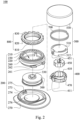
- Fig. 2 shows one exploded view of the fastening device 100 according to the 1st embodiment of Fig. 1
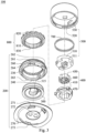
- Fig. 3 shows another exploded view of the fastening device 100 according to the 1st embodiment of Fig. 1
- the fastening device 100 can include a case 200, a spool 300 and a knob 500.
- the case 200 includes a housing 260 and a base 270, the housing 260 includes a receiving space 210 and two side holes 220, and the aforementioned two side holes 220 are communicated with the receiving space 210.
- the base 270 is detachably connected to the housing 260 and includes a continuous wall 274.
- the spool 300 is received in the receiving space 210 and a lace T1 (shown in Fig. 4 ) passes through the aforementioned two side holes 220 to be wound around the spool 300; the knob 500 is disposed on the case 200.
- the continuous wall 274 surrounds a lower edge 264 of the housing 260, and rotating the knob 500 relative to the case 200 causes the spool 300 to fasten the lace T1.
- the base 270 can be firmly combined with the housing 260, and the structural reliability thereof can be increased.
- the details of the fastening device 100 will be described in the following paragraphs.
- the housing 260 can further include a plurality of inner teeth 230 and a lower opening 240.
- the inner teeth 230 face to the receiving space 210, the lower opening 240 is communicated with the receiving space 210, and by assembling the base 270, the lower opening 240 can be closed to prohibit the spool 300 from falling out over the receiving space 210 from the lower opening 240.
- the continuous wall 274 is formed integrally, axial gaps are not recessed on the formed continuous wall 274 apparently, the continuous wall 274 can have a uniform or non-uniform height, but even the continuous wall 274 has the non-uniform height (a height of each region on the continuous wall 274 is different), the height of the continuous wall 274 changes smoothly instead of declining extremely as having the axial gaps.
- the base 270 can be assembled with the housing 260 stably, and the problem of breaking out or cracking caused by excessive stress at the corner of the axial gap of the conventional base during disassembling can be avoided, so the reliability of the fastening device 100 can be improved.
- the housing 260 can further include at least one tab 261, 262, 263, the base 270 can further include at least one hole 271, 272, 273, and the aforementioned at least one tab 261, 262, 263 correspondingly engages with the aforementioned at least one hole 271, 272, 273.
- a number of the aforementioned at least one tab 261, 262, 263 is three, the two tabs 261, 262 extends radially from a first side of the housing 260, and the other tab 263 is extended radially from a second side of the housing 260.
- the base 270 can include a guiding groove 275 and a bottom wall 276, the bottom wall 276 is connected to the continuous wall 274, a number of the aforementioned at least one hole 271, 272, 273 can be three, the three holes 271, 272, 273 are recessed radially on the continuous wall 274 near the bottom wall 276, the guiding groove 275 is located on the continuous wall 274 and aligned with the one hole 273 that corresponds to the other aforementioned tab 263.
- the base 270 can assemble with the housing 260, and during assembling, the tabs 261, 262 can be inserted into the holes 271, 272 first, and then the tab 263 is guided by the guiding groove 275 to be inserted into the hole 273.
- a number of each of the tabs and the holes can be changed according to the requirements, the guiding groove is not necessary to be disposed, and the present disclosure is not limited thereto.
- Fig. 4 shows a partial cross-sectional view of the fastening device 100 according to the 1st embodiment of Fig. 1 coupled to a lace T1
- Fig. 5 shows a cross-sectional view of the fastening device 100 according to the 1st embodiment of Fig. 1 coupled to the lace T1
- the base 270 is omitted.
- the spool 300 can be disc-shaped and includes an axial cylinder (not labeled), a first opening 321, a second opening (not shown) and a bottom opening 315, and the first opening 321 and the second opening are communicated with the bottom opening 315.
- a first end and a second end of the lace T1 can respectively pass through the first opening 321 and the second opening to be coupled with the spool 300, and the lace T1 is wound around the axial cylinder.
- the first end of the lace T1 can be exposed from the lower opening 240 after passing through the first opening 321 and the bottom opening 315
- the second end of the lace T1 can be exposed from the lower opening 240 after passing through the second opening and the bottom opening 315, so as to allow a user to tie, such that the lace T1 can be limited in the first opening 321 and the second opening
- the base 270 can be assembled to the housing 260.
- the knob 500 can include a rotary cover 530 and an inner plate 510, and the inner plate 510 is coupled to the rotary cover 530.
- the fastening device 100 can further include a locking unit 400, a ratchet ring 800 and a spring 700, the locking unit 400 is coupled to the knob 500 and the spool 300, the ratchet ring 800 is disposed in the housing 260, and the spring 700 is disposed on the ratchet ring 800 and surrounds the inner plate 510, so that when the knob 500 is rotated to drive the locking unit 400, the spool 300 linked therewith is rotated to retract the lace T1.
- the ratchet ring 800 includes a plurality of lower sloped teeth 810, a plurality of upper sloped grooves 820 and a plurality of ratchet teeth 830, both of the lower sloped teeth 810 and the upper sloped grooves 820 are located at an outer surface of the ratchet ring 800, the lower sloped teeth 810 are located below the upper sloped grooves 820 to correspond to the inner teeth 230, and the ratchet teeth 830 are located at an inner surface of the ratchet ring 800.
- the locking unit 400 is located in the ratchet ring 800 and includes an engaging disc 410, an inner gear 450, a plurality of coupling teeth 460 and three pawl arms 470.
- the inner gear 450 is located in the engaging disc 410, the inner gear 450 can move axially and relatively to the engaging disc 410 and include a spiral hole 451.
- the coupling teeth 460 are located in the inner gear 450 and detachably engaged with the engaging teeth 330, and the three pawl arms 470 are disposed at the engaging disc 410 and correspond to the ratchet teeth 830.
- the knob 500 can further include a guiding block 520 located at an inner wall of the rotary cover 530 and corresponding to the upper sloped grooves 820, the inner plate 510 can further include a spiral cylinder 511 and a coupling arm 512, the spiral cylinder 511 corresponds to the spiral hole 451, and the coupling arm 512 is selectively coupled to a buckling tab 411 of the engaging disc 410.
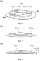
- Fig. 6 shows a three-dimensional schematic view of a base 270a of a fastening device according to a 2nd embodiment of the present disclosure
- Fig. 7 shows a side view of the base 270a according to the 2nd embodiment of Fig. 6
- Fig. 8 shows a cross-sectional view of the base 270a according to the 2nd embodiment of Fig. 6 taken along line 8-8
- the fastening device can further include a knob, a locking unit, a spool and a housing essentially.
- the knob can cover on the housing, the locking unit and the spool can disposed in the housing, the locking unit is coupled to the knob and includes a plurality of pawl arms interfering with inner teeth of the housing, the spool can be engaged with the locking unit, the locking unit can be disengaged with the spool through pulling or rotating the knob, such that the spool is allowed to freely rotate, and the aforementioned detail and the structure are not described herein again.
- the base 270a is configured for assembling the housing and has a non-uniform height, a continuous wall 271a can include two first sections 2711a and two second sections 2712a which are connected alternately to each other, and each of the first sections 2711a is higher than each of the second sections 2712a.
- a height H2 of each of the first sections 2711a is higher than a height H1 of each of the second sections 2712a, and each of the first sections 2711a is connected between the two second sections 2712a to form a continuous and integral wall without any gap.
- each of the first sections 2711a and the second sections 2712a is an arc structure which protrudes in the middle and heights of the two ends of each of the first sections 2711a and the second sections 2712a can be slightly decreased.
- the height of the intersection between the second sections 2712a and the first sections 2711a is lower than the height H1, such that the continuous wall 271a forms a wave-shaped structure.
- Fig. 9 shows a three-dimensional schematic view of a base 270b of a fastening device according to a 3rd embodiment of the present disclosure
- Fig. 10 shows a side view of the base 270b according to the 3rd embodiment of Fig. 9.
- Fig. 11 shows a cross-sectional view of the base 270b according to the 3rd embodiment of Fig. 9 taken along line 11-11.
- a continuous wall 271b of the base 270b has a uniform height, that is, a height of each section of the continuous wall 271b is the same.
- Fig. 12 shows a three-dimensional schematic view of a base 270c of a fastening device according to a 4th embodiment of the present disclosure
- Fig. 13 shows a side view of the base 270c according to the 4th embodiment of Fig. 12
- Fig. 14 shows a cross-sectional view of the base 270c according to the 4th embodiment of Fig. 12 taken along line 14-14.
- a continuous wall 271c of the base 270c has two sections 2711c.
- the two sections 2711c are connected to each other symmetrically, and each of the sections 2711c is an arc structure and the middle portion of each of the sections 2711c is higher than the two lateral portions of each of the sections 2711c, and the two sections 2711c are connected to each other via the two lateral portions thereof.
- Fig. 15 shows a three-dimensional schematic view of a base 270d of a fastening device according to a 5th embodiment of the present disclosure
- Fig. 16 shows a side view of the base 270d according to the 5th embodiment of Fig.
- Fig. 17 shows a cross-sectional view of the base 270d according to the 5th embodiment of Fig. 15 taken along line 17-17.
- the base 270d is similar to the base 270a, a continuous wall 271d includes two first sections 2711d and two second sections 2712d, each of the first sections 2711d is an arc structure which protrudes in the middle, but a height of each part of the second sections 2712d are uniform.
- Fig. 18 shows a three-dimensional schematic view of a base 270e of a fastening device according to a 6th embodiment of the present disclosure
- Fig. 19 shows a side view of the base 270e according to the 6th embodiment of Fig. 18
- Fig. 20 shows a cross-sectional view of the base 270e according to the 6th embodiment of Fig. 18 taken along line 20-20.
- the base 270e is similar to the base 270c, a continuous wall 271e has two sections 2711e, but each of the sections 2711e is an arc structure and the middle portion of each of the sections 2711e is lower than the two lateral portions of each of the sections 2711e, and the two sections 2711e are connected to each other via the two lateral portions thereof.
- Fig. 21 shows one exploded view of a case 200f of a fastening device according to a 7th embodiment of the present disclosure
- Fig. 22 shows another exploded view of the case 200f according to the 7th embodiment of Fig. 21
- Fig. 23 shows a cross-sectional view of the assembly of the case 200f according to the 7th embodiment of Fig. 21
- the case 200f can include a base 270f and a housing 260f, the housing 260f is disposed on the base 270f, the housing 260f can include a flange 264f extending outwardly and radially, and the flange 264f rests on a continuous wall 271f.
- the housing 260f can further include an extending portion 265f, and the extending portion 265f extends downwardly and axially from the flange 264f.
- the base 270f can further include an aligning groove 272f, and the aligning groove 272f is located on the continuous wall 271f and aligned with the extending portion 265f.
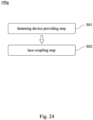
- Fig. 24 shows a flow chart of a lace assembling method 100g according to an 8th embodiment of the present disclosure.
- the lace assembling method 100g is configured for connecting a lace T1 to a fastening device 100, and the lace assembling method 100g includes a fastening device providing step S01 and a lace coupling step S02.
- the fastening device 100 includes a case 200, a spool 300 and a knob 500
- the case 200 includes a housing 260 and a base 270
- the housing 260 includes a receiving space 210 and two side holes 220 communicated with the receiving space 210
- the base 270 is detachably connected to the housing 260 and includes a continuous wall 274, when the base 270 is connected to the housing 260, the continuous wall 274 surrounds a lower edge 264 of the housing 260, the spool 300 is received in the receiving space 210, and the aforementioned two side holes 220 are configured for the lace T1 to pass therethrough to be wound around spool 300.
- a first end of the lace T1 and a second end of the lace T1 are exposed from the housing 260 and the spool 300 after passing through the housing 260, and then the first end and the second end are knotted, so as to allow the lace T1 to be coupled to the spool 300.
- a user Before assembling the base 270, a user can respectively align a first opening 321 and a second opening of the spool 300 with the two side holes 220, then allow the first end of the lace T1 to pass through one of the side holes 220 and the first opening 321 after passing through openings on a wearable object, and allow the second end of the lace T1 to pass through the other one of the side holes 220 and the second opening after passing through openings on the wearable object, at last limit the lace T1 in the spool 300 through knotting.
- the base 270 can be connected to the housing 260, and the assembling of the lace T1 is completed.
Landscapes
- Clamps And Clips (AREA)
- Storing, Repeated Paying-Out, And Re-Storing Of Elongated Articles (AREA)
- Footwear And Its Accessory, Manufacturing Method And Apparatuses (AREA)
- Storage Of Web-Like Or Filamentary Materials (AREA)
- Connection Of Plates (AREA)
Applications Claiming Priority (2)
| Application Number | Priority Date | Filing Date | Title |
|---|---|---|---|
| US17/144,155 US11607014B2 (en) | 2016-11-11 | 2021-01-08 | Fastening device and lace assembling method |
| PCT/CN2021/107298 WO2022148001A1 (fr) | 2021-01-08 | 2021-07-20 | Dispositif de fixation et procédé d'assemblage de lacet |
Publications (2)
| Publication Number | Publication Date |
|---|---|
| EP4275540A1 true EP4275540A1 (fr) | 2023-11-15 |
| EP4275540A4 EP4275540A4 (fr) | 2024-12-04 |
Family
ID=82357119
Family Applications (1)
| Application Number | Title | Priority Date | Filing Date |
|---|---|---|---|
| EP21917044.6A Pending EP4275540A4 (fr) | 2021-01-08 | 2021-07-20 | Dispositif de fixation et procédé d'assemblage de lacet |
Country Status (5)
| Country | Link |
|---|---|
| EP (1) | EP4275540A4 (fr) |
| JP (2) | JP7813246B2 (fr) |
| KR (1) | KR20230129005A (fr) |
| CN (1) | CN115103611A (fr) |
| WO (1) | WO2022148001A1 (fr) |
Families Citing this family (1)
| Publication number | Priority date | Publication date | Assignee | Title |
|---|---|---|---|---|
| CN219460470U (zh) * | 2023-03-30 | 2023-08-04 | 李惠卿 | 一种系带底座结构以及系带装置 |
Family Cites Families (12)
| Publication number | Priority date | Publication date | Assignee | Title |
|---|---|---|---|---|
| DE202011101828U1 (de) * | 2011-06-14 | 2011-08-17 | Chin-Chu Chen | Schuhschnurbinder |
| TWI513423B (zh) * | 2013-11-11 | 2015-12-21 | Chin Chu Chen | 帶體收放裝置及其收放方法 |
| US11607014B2 (en) * | 2016-11-11 | 2023-03-21 | Chin-Chu Chen | Fastening device and lace assembling method |
| US11751634B2 (en) * | 2016-11-11 | 2023-09-12 | Chin-Chu Chen | Fastening device and lace assembling method |
| KR101723579B1 (ko) * | 2016-11-29 | 2017-04-06 | 주식회사 신경 | 와이어 조임장치 |
| KR102822775B1 (ko) | 2016-12-09 | 2025-06-20 | 보아 테크놀러지, 인크. | 릴 기반의 폐쇄 시스템 |
| KR101804801B1 (ko) * | 2017-03-13 | 2017-12-05 | 하민우 | 와이어 조임장치 |
| KR102314745B1 (ko) * | 2018-09-07 | 2021-10-19 | 타이렌 주식회사 | 끈 조절장치 |
| CN111115388B (zh) * | 2018-10-30 | 2021-11-19 | 陈金柱 | 紧固装置 |
| TWI719354B (zh) * | 2018-10-30 | 2021-02-21 | 陳金柱 | 緊固裝置 |
| CN111846339B (zh) * | 2019-04-30 | 2022-04-15 | 陈金柱 | 紧固装置 |
| KR102160426B1 (ko) | 2020-07-14 | 2020-09-28 | 주식회사 스핀온 | 와이어 조임장치 |
-
2021
- 2021-07-20 CN CN202180014052.2A patent/CN115103611A/zh active Pending
- 2021-07-20 KR KR1020237015607A patent/KR20230129005A/ko active Pending
- 2021-07-20 WO PCT/CN2021/107298 patent/WO2022148001A1/fr not_active Ceased
- 2021-07-20 EP EP21917044.6A patent/EP4275540A4/fr active Pending
- 2021-07-20 JP JP2022575855A patent/JP7813246B2/ja active Active
-
2025
- 2025-11-13 JP JP2025194452A patent/JP2026032032A/ja active Pending
Also Published As
| Publication number | Publication date |
|---|---|
| JP2026032032A (ja) | 2026-02-25 |
| JP7813246B2 (ja) | 2026-02-12 |
| CN115103611A (zh) | 2022-09-23 |
| WO2022148001A1 (fr) | 2022-07-14 |
| EP4275540A4 (fr) | 2024-12-04 |
| JP2024502221A (ja) | 2024-01-18 |
| KR20230129005A (ko) | 2023-09-05 |
Similar Documents
| Publication | Publication Date | Title |
|---|---|---|
| US11607014B2 (en) | Fastening device and lace assembling method | |
| KR102576708B1 (ko) | 체결 디바이스 | |
| US12419390B2 (en) | Fastening device | |
| US12207706B2 (en) | Fastening device | |
| JP2022190050A (ja) | 締結装置 | |
| KR102464463B1 (ko) | 고정 디바이스 | |
| EP4179912A1 (fr) | Dispositif de fixation | |
| US20250024916A1 (en) | Fastening device | |
| JP2024020177A (ja) | 締結装置 | |
| EP4321050A1 (fr) | Dispositif de fixation | |
| TW202040027A (zh) | 緊固裝置 | |
| CN114557512A (zh) | 紧固装置 | |
| TWI719354B (zh) | 緊固裝置 | |
| JP2026032032A (ja) | 締結装置及び線状物取付方法 | |
| TWI659919B (zh) | 緊固裝置 | |
| TWI813945B (zh) | 緊固裝置及繫線收放方法 |
Legal Events
| Date | Code | Title | Description |
|---|---|---|---|
| STAA | Information on the status of an ep patent application or granted ep patent |
Free format text: STATUS: THE INTERNATIONAL PUBLICATION HAS BEEN MADE |
|
| PUAI | Public reference made under article 153(3) epc to a published international application that has entered the european phase |
Free format text: ORIGINAL CODE: 0009012 |
|
| STAA | Information on the status of an ep patent application or granted ep patent |
Free format text: STATUS: REQUEST FOR EXAMINATION WAS MADE |
|
| 17P | Request for examination filed |
Effective date: 20230808 |
|
| AK | Designated contracting states |
Kind code of ref document: A1 Designated state(s): AL AT BE BG CH CY CZ DE DK EE ES FI FR GB GR HR HU IE IS IT LI LT LU LV MC MK MT NL NO PL PT RO RS SE SI SK SM TR |
|
| DAV | Request for validation of the european patent (deleted) | ||
| DAX | Request for extension of the european patent (deleted) | ||
| A4 | Supplementary search report drawn up and despatched |
Effective date: 20241031 |
|
| RIC1 | Information provided on ipc code assigned before grant |
Ipc: A43C 11/16 20060101AFI20241025BHEP |