EP4275559A2 - Vorrichtung und verfahren für eine verbesserte kaffeemaschine - Google Patents
Vorrichtung und verfahren für eine verbesserte kaffeemaschine Download PDFInfo
- Publication number
- EP4275559A2 EP4275559A2 EP23200706.2A EP23200706A EP4275559A2 EP 4275559 A2 EP4275559 A2 EP 4275559A2 EP 23200706 A EP23200706 A EP 23200706A EP 4275559 A2 EP4275559 A2 EP 4275559A2
- Authority
- EP
- European Patent Office
- Prior art keywords
- steam
- espresso machine
- wand
- controller
- pressure
- Prior art date
- Legal status (The legal status is an assumption and is not a legal conclusion. Google has not performed a legal analysis and makes no representation as to the accuracy of the status listed.)
- Pending
Links
Images










Classifications
-
- A—HUMAN NECESSITIES
- A47—FURNITURE; DOMESTIC ARTICLES OR APPLIANCES; COFFEE MILLS; SPICE MILLS; SUCTION CLEANERS IN GENERAL
- A47J—KITCHEN EQUIPMENT; COFFEE MILLS; SPICE MILLS; APPARATUS FOR MAKING BEVERAGES
- A47J31/00—Apparatus for making beverages
- A47J31/44—Parts or details or accessories of beverage-making apparatus
- A47J31/4403—Constructional details
-
- A—HUMAN NECESSITIES
- A47—FURNITURE; DOMESTIC ARTICLES OR APPLIANCES; COFFEE MILLS; SPICE MILLS; SUCTION CLEANERS IN GENERAL
- A47J—KITCHEN EQUIPMENT; COFFEE MILLS; SPICE MILLS; APPARATUS FOR MAKING BEVERAGES
- A47J31/00—Apparatus for making beverages
- A47J31/44—Parts or details or accessories of beverage-making apparatus
-
- A—HUMAN NECESSITIES
- A47—FURNITURE; DOMESTIC ARTICLES OR APPLIANCES; COFFEE MILLS; SPICE MILLS; SUCTION CLEANERS IN GENERAL
- A47J—KITCHEN EQUIPMENT; COFFEE MILLS; SPICE MILLS; APPARATUS FOR MAKING BEVERAGES
- A47J31/00—Apparatus for making beverages
- A47J31/24—Coffee-making apparatus in which hot water is passed through the filter under pressure, i.e. in which the coffee grounds are extracted under pressure
-
- A—HUMAN NECESSITIES
- A47—FURNITURE; DOMESTIC ARTICLES OR APPLIANCES; COFFEE MILLS; SPICE MILLS; SUCTION CLEANERS IN GENERAL
- A47J—KITCHEN EQUIPMENT; COFFEE MILLS; SPICE MILLS; APPARATUS FOR MAKING BEVERAGES
- A47J31/00—Apparatus for making beverages
- A47J31/24—Coffee-making apparatus in which hot water is passed through the filter under pressure, i.e. in which the coffee grounds are extracted under pressure
- A47J31/34—Coffee-making apparatus in which hot water is passed through the filter under pressure, i.e. in which the coffee grounds are extracted under pressure with hot water under liquid pressure
- A47J31/36—Coffee-making apparatus in which hot water is passed through the filter under pressure, i.e. in which the coffee grounds are extracted under pressure with hot water under liquid pressure with mechanical pressure-producing means
-
- A—HUMAN NECESSITIES
- A47—FURNITURE; DOMESTIC ARTICLES OR APPLIANCES; COFFEE MILLS; SPICE MILLS; SUCTION CLEANERS IN GENERAL
- A47G—HOUSEHOLD OR TABLE EQUIPMENT
- A47G19/00—Table service
- A47G19/12—Vessels or pots for table use
- A47G19/14—Coffee or tea pots
-
- A—HUMAN NECESSITIES
- A47—FURNITURE; DOMESTIC ARTICLES OR APPLIANCES; COFFEE MILLS; SPICE MILLS; SUCTION CLEANERS IN GENERAL
- A47J—KITCHEN EQUIPMENT; COFFEE MILLS; SPICE MILLS; APPARATUS FOR MAKING BEVERAGES
- A47J31/00—Apparatus for making beverages
-
- A—HUMAN NECESSITIES
- A47—FURNITURE; DOMESTIC ARTICLES OR APPLIANCES; COFFEE MILLS; SPICE MILLS; SUCTION CLEANERS IN GENERAL
- A47J—KITCHEN EQUIPMENT; COFFEE MILLS; SPICE MILLS; APPARATUS FOR MAKING BEVERAGES
- A47J31/00—Apparatus for making beverages
- A47J31/24—Coffee-making apparatus in which hot water is passed through the filter under pressure, i.e. in which the coffee grounds are extracted under pressure
- A47J31/30—Coffee-making apparatus in which hot water is passed through the filter under pressure, i.e. in which the coffee grounds are extracted under pressure with hot water under steam pressure
-
- A—HUMAN NECESSITIES
- A47—FURNITURE; DOMESTIC ARTICLES OR APPLIANCES; COFFEE MILLS; SPICE MILLS; SUCTION CLEANERS IN GENERAL
- A47J—KITCHEN EQUIPMENT; COFFEE MILLS; SPICE MILLS; APPARATUS FOR MAKING BEVERAGES
- A47J31/00—Apparatus for making beverages
- A47J31/44—Parts or details or accessories of beverage-making apparatus
- A47J31/4489—Steam nozzles, e.g. for introducing into a milk container to heat and foam milk
-
- A—HUMAN NECESSITIES
- A47—FURNITURE; DOMESTIC ARTICLES OR APPLIANCES; COFFEE MILLS; SPICE MILLS; SUCTION CLEANERS IN GENERAL
- A47J—KITCHEN EQUIPMENT; COFFEE MILLS; SPICE MILLS; APPARATUS FOR MAKING BEVERAGES
- A47J31/00—Apparatus for making beverages
- A47J31/44—Parts or details or accessories of beverage-making apparatus
- A47J31/46—Dispensing spouts, pumps, drain valves or like liquid transporting devices
-
- A—HUMAN NECESSITIES
- A47—FURNITURE; DOMESTIC ARTICLES OR APPLIANCES; COFFEE MILLS; SPICE MILLS; SUCTION CLEANERS IN GENERAL
- A47J—KITCHEN EQUIPMENT; COFFEE MILLS; SPICE MILLS; APPARATUS FOR MAKING BEVERAGES
- A47J31/00—Apparatus for making beverages
- A47J31/44—Parts or details or accessories of beverage-making apparatus
- A47J31/46—Dispensing spouts, pumps, drain valves or like liquid transporting devices
- A47J31/469—Details of hydraulic circuits
-
- A—HUMAN NECESSITIES
- A47—FURNITURE; DOMESTIC ARTICLES OR APPLIANCES; COFFEE MILLS; SPICE MILLS; SUCTION CLEANERS IN GENERAL
- A47J—KITCHEN EQUIPMENT; COFFEE MILLS; SPICE MILLS; APPARATUS FOR MAKING BEVERAGES
- A47J31/00—Apparatus for making beverages
- A47J31/44—Parts or details or accessories of beverage-making apparatus
- A47J31/60—Cleaning devices
Definitions
- the present invention relates to fluid boilers and in particular to regulated control of fluid boilers.
- the invention has been developed primarily for use as a controlled boiler method and apparatus of an espresso machine and will be described hereinafter with reference to this application. However, it will be appreciated that the invention is not limited to this particular field of use.
- Known espresso machine control both the pressure and dose of water delivered in producing a shot of espresso coffee It will be appreciated that the pressure is typically set to between nine and ten bar.
- the dose is typically about 30mL, and is delivered in between twenty to forty seconds.
- a pre-infusion stage has been used to wet the coffee grinds to allow expansion within a filter basket, thereby assisting in trapping fine grinds and restricting water from tracking though the filter.
- the water delivered in this pre-infusion stage usually has a pressure between one to five bar.
- Espresso machines are also known to have steam wands.
- the steam wand omits steam that can be used, for example, to heat and froth milk.
- the steam output is regulated by a valve such as a needle valve.
- a needle valve provides a variable steam output but must be rotated numerous times when proceeding from a closed state to a fully opened state.
- an espresso machine with a heating unit, a controller, and a steam wand, the espresso machine including:
- the controller is configured to cause a series of bursts of steam for purging or clearing the steam wand of frothing debris after the steam cycle.
- the steam wand is pivotable from a use position to a home position.
- the espresso machine further includes: a switch operably associated with the steam wand, the switch providing a home position signal to the controller when the steam wand is pivoted to the home position.
- the controller is configured to cause a burst of steam or a series of bursts of steam for purging or clearing the steam wand in response to the home position signal.
- the steam cycle is an automatic cycle.
- the espresso machine further includes a user interface, and wherein:
- the espresso machine further includes:
- the espresso machine further includes: a first switch providing a first signal to the controller for initiating the manual steaming mode of operation when the lever is in the manual steam position, and a second switch providing second signal to the controller for initiating the automatic steam mode of operation when the lever is in the automatic steam position.
- the controller causes the user interface to generate an audible or visual warning before the burst of steam or the series of bursts of steam.
- the espresso machine further includes: a temperature sensor that measures a temperature of the contents of a container in which the steam wand is located, the temperature sensor being configured to transmit a temperature signal to the controller.
- the controller when the lever is in the manual position, the controller causes the temperature of the contents to be displayed by the user interface; and the controller further causes the manual steaming mode to cease after the lever is returned to the neutral position.
- the automatic steam mode is ceased by the controller in response to the temperature signal.
- the solenoid valve is operable by the controller to deliver a variable flow of steam into the steam wand.
- a flow measurement apparatus for measuring a resultant flow delivered by a pump coupled to an over pressure valve, the apparatus comprising:
- resultant flow can be determined (or calculated) in real time, and used to stop the operation of the pump when a suitable dose has been delivered.
- an espresso machine comprising a flow measurement apparatus as herein disclosed, for measuring a shot dose delivered by a pump coupled to an over pressure valve.
- the espresso machine further comprises a pump power modification module as herein disclosed, for providing pre-infusion.
- an espresso machine comprising a pump power modification module as herein disclosed, for providing pre- infusion.
- the espresso machine further comprises a flow measurement apparatus as herein disclosed, for measuring a shot dose delivered by a pump coupled to an over pressure valve.
- the pump power modification module can enable pressure profiling during an espresso production cycle. More preferably, the pressure profile can be preset or user configurable. Most preferably, the pressure profile can take the form of power-time profile indicative of electrical power delivered to a respective pump.
- a method of flow measurement for measuring a resultant flow delivered by a pump coupled to an over pressure valve comprising the steps of:
- calculating resultant flow can be performed in real time, and used to stop the operation of the pump when a suitable dose has been delivered.
- an espresso machine comprising a processor device adapted to perform a method of flow measurement as herein disclosed, for measuring a shot dose delivered by a pump coupled to an over pressure valve.
- an apparatus for controlling overflow from a fluid reservoir comprising:
- an espresso machine comprising:
- the water tank is inserted from the rear of the espresso machine body.
- the water tank is preferably inserted from the side of the espresso machine body.
- an apparatus for receiving a removable fluid reservoir comprising:
- an espresso machine comprising:
- the water tank is inserted from the rear of the espresso machine body.
- the water tank is preferably inserted from the side of the espresso machine body.
- the water tank includes a overflow aperture in fluid communication with a drip tray.
- the espresso machine includes a flow measurement apparatus.
- an apparatus for providing control of a steam output comprising:
- the apparatus further comprising a pump that draws a fluid from a fluid reservoir, and supplies the fluid it to a steam boiler; the boiler supplying steam a solenoid activated valve used to start and stop the flow of steam from the boiler to the wand assembly.
- an espresso machine comprising:
- the valve is a ball valve.
- a paddle is affixed to a knob.
- a steam control apparatus for an espresso machine comprises:
- the steam control apparatus includes a switch sensor element for providing a data (or lodging) signal to a computing module. More preferably, the data signal is indicative for the apparatus being in a fully open configuration wherein output of the steam wand is in fluid communication with a steam boiler.
- the valve is a ball valve in fluid communication with the steam wand assembly; and the rotating control element comprises a hub having a radially extending lever element; the hub being rotatably mounted with respect to the body; the hub and lever element being operative coupled to the ball valve; and wherein the apparatus can be configured from a fully closed configuration to a fully open configuration by rotation of the hub.
- allowable rotation of the control element is less than 180 degrees.
- the apparatus includes a switch sensor element for providing a data signal to a processor module. More preferably, the data signal is indicative for the apparatus being in a fully open configuration wherein output of the steam wand assembly is in fluid communication with a steam boiler.
- the apparatus further comprising a pump that draws a fluid from a fluid reservoir, and supplies the fluid it to a steam boiler; the boiler supplying steam a solenoid activated valve used to start and stop the flow of steam from the boiler to the wand assembly.
- the solenoid activated valve is a three way two position solenoid valve used to start and stop the flow of steam from the boiler to the wand assembly.
- the wand assembly is substantially constructed in plastics so as to isolate heat in a wand nozzle.
- a temperature sensor element monitors temperature of the wand nozzle. More preferably, the temperature sensor element is a thermistor. Most preferably, the steam wand assembly has an output steam nozzle associated with a thermistor.
- a steam path is an open flow path to the atmosphere for restricting milk from being siphoned back into the wand assembly.
- the solenoid valve is adapted to supply either unadulterated steam from the boiler, or to allow flow of atmosphere to the venturi.
- the rotatable control element activates one or more switch element for controlling a steam generation process.
- the steam wand assembly is associated with a switch element for enabling detection that the steam wand assembly has been returned to a predetermined home position.
- the apparatus further comprises a pressure sensor element for monitoring the steam pressure at the steam wand.
- the apparatus disclosed herein can be a coffee machine. More particularly the apparatus disclosed herein can be an espresso coffee machine.
- the apparatus disclosed herein can be used as a coffee machine. More particularly the apparatus disclosed herein can be used as an espresso coffee machine.
- a coffee making apparatus for providing pressure feedback control of brew water output during a coffee production cycle, the apparatus comprising:
- predetermined water pressure is a pressure profile
- the processor module enabling brew water to be supplied according to the pressure profile during a production cycle.
- the pressure profile is the form of pressure-time profile used to control electrical power delivered to the pump.
- the pressure profile is preset.
- the pressure profile is user selected using a user interface.
- the pressure profile is user configurable.
- the pressure profile is user configurable using a user interface.
- a pressure profile is user selected using a user interface.
- a pressure profile is user configurable using a user interface.
- the processor module can enable brew water to be supplied according to a pressure profile during a pre-infusion cycle. More preferably, the pressure profile during the pre-infusion cycle provides a controlled low pressure pre-infusion.
- the pressure profile during the pre-infusion cycle provides a controlled low pressure pre-infusion that enables the coffee grounds to be wet without forcing water through. More preferably, water delivered in the pre-infusion stage is provided at a pressure of about three bar. More preferably, water delivered in this pre-infusion stage is provided at a pressure from one to five bar.
- the processor module is coupled to a power modification module for controlling electrical power delivered to the pump; the processor module controls the power modification module to enable brew water to be supplied according to the predetermined water pressure.
- Shots of espresso are typically brewed by the pressurised flow of hot water through densely-packed finely-ground coffee. This forced diffusion of water through coffee grounds, results in the production of espresso coffee. Quality, flavour and taste of any resultant espresso coffee are influenced by a plurality of factors, which include the texture of the ground coffee, the density of the ground coffee packing, and temperature and pressure of the water used. By maintaining these factors in appropriate proportions, it is possible to produce substantially consistent shots of espresso.
- Pump based espresso machines rely, at least in part, upon the pressure (usually measured in bars) of the pump to make a suitable espresso coffee.
- these pump based coffee machines 100 can include: a water reservoir 110 (typically internal), showerhead or distributor 122, and filter basket 124 (for holding the coffee grounds).
- a steam wand 130 and steam valve 132 may be included for frothing milk.
- a drip tray 140 is typically provided for collecting spillages and excess water.
- a series of user control inputs 150 can be provided for setting at least some of the parameters (or factors) associated with producing espresso coffee.
- espresso machines have an integrated coffee grinder 160.
- This can include a hopper 162 for feeding coffee beans to a grinder and an output 164 for filling the filter basket (when provided there below) with coffee grounds.
- FIG. 2 shows a schematic for an espresso coffee machine 200.
- This coffee machine comprises a water reservoir 210, having a reed switch tank level sensor 212.
- Egress from the water reservoir includes passing though a filter 214 that is in fluid communications with two egress flow paths 216 and 218.
- a first egress path 216 is for communicating or delivering water from the reservoir 210 to a steam boiler 250.
- This egress path includes a protection filter 220 that communicates water to a pump 221 that supplies water at a pre-determined pressure.
- a safety relief valve 222 is included to limit the water pressure provided to the steam boiler 250. In the event of over pressure occurring in this fluid line, the relief valve 222 provides or diverts water to the drip tray 240 using fluid line 224.
- the pump 221 provides water with about three bar pressure to the steam boiler 250 (using fluid line 223). For steam system, the pump is supplied the water at approx. 3 bar to refill the boiler.
- the safety relief valve 222 is set to activate at a higher pressure, and is used for protection.
- the steam boiler 250 is used to convert water provided by fluid line 223 to steam.
- the boiler includes a heating element 252, a water level probe 256, a temperature sensing element (for example a thermistor) 257, a thermal fuse and thermostat 258, and vacuum breather valve 259.
- the steam boiler is a 0.80 litre boiler.
- this boiler 250 can be constructed from any one or more materials in a set comprising diecast-aluminium (preferably teflon-lined), stainless steel or brass.
- the heating element 252 is preferably an immersed 1000 watt heater element.
- this heating element can be constructed from any one or more materials in a set comprising stainless steel and Incoloy.
- the heating element can have alternative power ratings that are suitable for creating steam within the boiler.
- the water level probe 256 preferably uses three probes to monitor water level and is substantially comprised of stainless steel probes.
- the thermistor 257 has a maximum temperature rating of about 200 degrees Celsius.
- egress steam 272 from the steam boiler 250 is released from a continuously variable delivery ball valve 274 though a steam wand 274.
- the ball valve has a maximum temperature rating of about 150 degrees Celsius, a nominal working pressure of about two bar and a maximum pressure rating of about eight bar.
- a second water egress path 218 communicates water from the water tank 210 to a coffee boiler 260.
- This egress path includes a protection filter 230, a first flow meter 233 and a pump 234.
- the pump 234 further includes an over pressure (or safety relief) valve 235. This over pressure valve 235 is adapted to limit the water pressure provided to line 236, typically to between nine bar and ten bar.
- the over pressure valve 235 is typically set to a pressure set-point, typically about ten bar, such that when water pressure exceeds this set-point a portion of the water is fed back through a return line 237 to the reservoir 210, thereby maintaining a pressure set-point.
- the amount of water fed back through a return line 237 can be measured by a second flow meter 238.
- the main egress path 236 proceeds through the steam boiler 250 via a heat exchanger 254 and then to the coffee boiler 260.
- the coffee boiler 260 includes a heating element 262, a water level probe 266, a thermistor 267 and a thermal fuse and thermostat 268.
- the coffee boiler 260 is a 0.30 litre boiler.
- this boiler 260 can be constructed from any one or more materials in a set comprising diecast-aluminium (preferably teflon-lined), stainless steel,. or brass.
- the heating element 262 is an immersed stainless steel 600 watt heating element.
- the water level probe 266 preferably uses two probes to monitor water level and is substantially comprised of stainless steel probes.
- the thermistor 267 has a maximum temperature rating of about 150 degrees Celsius.
- egress from the coffee boiler is used to provide hot water 282, via a continuously variable output needle valve 284, though a hot water wand 286.
- the needle valve 282 preferably has a maximum temperature rating of about 120 degrees Celsius and a working pressure of about fifteen bar.
- egress from the coffee boiler is also used to provide hot water to a coffee showerhead 292 for providing coffee 294.
- a solenoid 296 releases hot water to the showerhead 292 for making coffee.
- the showerhead 294 further has a pressure gauge 298 for displaying the pressure of hot water provided by the coffee boiler.
- the solenoid 296 has a maximum working pressure of about sixteen bar, and a maximum fluid temperature of about 160 degrees Celsius.
- the solenoid 296 body can be constructed from any one or more materials in a set comprising stainless steel and brass. Different protective coatings can be applied to the solenoid, including nickel-plating.
- the fluid lines are either Teflon tubing or silicon tubing.
- pumps 221 and 234 can be vibration (displacement) pumps, although alternative pump technologies can be used. Vibration pumps typically produce around fifteen bar to eighteen bar unregulated pressure, which is typically considered too high for espresso extraction.
- a fixed or variable over pressure valve can be installed.
- a known method of measuring the dose includes having a flow meter located proximal to the showerhead. It will be appreciated that any installation in the flow proximal to the showerhead requires that the over pressure valve be suited to operation in a high temperature and a high pressure environment. The construction and operation of over pressure valves will be discussed in more detail below.
- the apparatus 200 includes a processor 202 for receiving inputs from user interface 204 and water level probes, thermistors, and thermal fuse/thermostats.
- the processor is also used to control/activate heating elements and pumps.
- a pair of flow meters are used, the first flow meter 230 to measure the feed flow to the pump and the second flow meter 237 to measure return flow from an over pressure valve 235.
- the resultant flow delivered to the coffee boiler 260 (and therefore to the showerhead 296) can be calculated by subtracting the return flow from the feed flow.
- a dose measure can be determined. It will be appreciated that this calculation can be performed in real time, and used to stop the pump when a suitable dose has been delivered through the showerhead.
- a flow measurement apparatus for measuring a resultant flow delivered by a pump coupled to an over pressure valve has a first flow meter for measuring feed flow to the pump, and a second flow meter for measuring return flow from the over pressure.
- a resultant flow delivered by a pump can be determined by subtracting measured return flow from measured feed flow.
- a method 300 of flow measurement for measuring a resultant flow delivered by a pump coupled to an over pressure valve comprising the steps of monitoring (or measuring), using a first flow meter, feed flow to the pump 320; monitoring (or measuring), using a second flow meter, return flow from the overpressure valve 330; and calculating resultant flow, at least in part, by subtracting measured return flow from measured feed flow 340.
- this calculation can be performed in real time, and used to stop the pump (350) when a suitable dose has been delivered through the showerhead.
- the pressure, dose amount, duration can be preset or user configurable (using user interface 204 and the machine's controller).
- a pre-infusion stage is often initiated to wet the coffee grinds to allow expansion within a filter basket, thereby assisting in trapping fine grinds and restricting water tracking though the filter.
- the water delivered in this pre-infusion stage is usually provided at a pressure of about three bar.
- pre-infusion pressure can range from 1 to 5 bar.
- the pump 230 can be controlled to provide a lower (or reduced) pressure pre-infusion stage. This can be achieved by reducing the electrical power supplied to the pump during this stage.
- a power modification module as discussed in more detail below, can be utilised to enable processor control of electrical power supplied to the pump.
- the electrical power supplied to the pump enables the pump to produce a lower than normal pressure.
- the water flowing during the pre-infusion stage may (or may not) be counted toward a subsequent dose has been delivered through the showerhead.
- Power control and flow measurement can be combined to enable measurement of a resultant pre-infusion dose.
- the pressure, dose amount, duration can be preset or user configurable (using user interface 204).
- a percentage of the maximum pump pressure available can be configured.
- a pressure profile could comprise 30% of the maximum pressure for 5 seconds, then 100% pressure for 20 seconds, then 70% pressure for a final 5 secs.
- the system may exercise a method of volume output configured such that the delivery would entail a 5ml at 30%, a 20ml at 100%, and a 5ml at 70% distribution.
- a power modification module can further enable pressure profiling during an espresso production cycle.
- a pressure profile can be preset or user configurable (using user interface 204 and the machine's controller). Pressure profiling can take the form of power-time profile indicative of electrical power delivered to a respective pump.
- the illustrated apparatus discloses an espresso machine that can provide a dose having a regulated pressure and volume.
- the illustrated apparatus further discloses an espresso machine that can provide a controlled low pressure pre-infusion.
- An over pressure valve also known as an expansion valve, can be used to regulate water flow pressure within an espresso machine.
- the regulated pressure can be fixed or adjusted.
- an over pressure valve can regulate pressure down, to between nine bar to ten bar on many vibration pump based machines.
- an over pressure valve 400 comprises an ingress part or aperture 410 and an egress part or aperture 420.
- An over pressure part or aperture 430 is included for releasing water to substantially maintain a pressure set-point.
- a release seal 432 typically in the form of a ball, rubber pad on brass piston or similar, is biased to a closed position by a spring 434 (the tension or compression on the spring can be adjusted 436) against an exit aperture 438. When pressure exceeds in the set-point, the release seal 432 opens allowing water to flow toward the over pressure aperture 430.
- the exit aperture is in fluid communication with the over pressure aperture, typically for routing excess water back to the tank.
- over pressure valves are adapted to be fixed to a 'T' piece, wherein the 'T' piece defines an ingress aperture and an egress aperture.
- Flow rate capability is typically determined by the size of the over pressure valve.
- Phase controlled power modification is a method of providing alternating current power to a load only during periods of an alternating current power cycle.
- FIG. 6A shows a sine wave 600 indicative of alternating current power (voltage or current). Each time the line equals the neutral or ground line, a ⁇ Zero Crossing' occurs.
- Circuit diagrams power modification is provided by Motorola data sheet for MOC30xx variants. It has applicability to inductive and resistive loads.
- FIG. 5A shows a schematic view of a circuit 500 used to modify power suppled to a pump, shown using silicon controlled rectifier (SCR) 530;
- SCR silicon controlled rectifier
- a silicon controlled rectifier is typically considered as a device which is either on or off. Once turned on, it will only turn off when there is no current flowing through it. The gate requires a small current to switch the SCR on. An SCR will only conduct current one way, so if the current changes polarity, it will turn off, because it won't allow any current to flow.
- FIG. 5B shows a schematic view of a circuit 550 used to modify power suppled to a pump, shown using a triode for alternating current (TRIAC) 580.
- TRIAC triode for alternating current
- a TRIAC schematically resembles two SCRs back to back, with only one gate terminal from one of the anodes. This allows AC operation, but every time the current changes polarity the TRIAC turn off (unless the gate is held high).
- Phase Control enables only portions of the AC cycle to be coupled to the load 540. This can be performed by a TRIAC, or two back to back SCRs.
- alternating current sources have two zero crossings every cycle, in which no current should be flowing.
- the frequency of zero crossings is about 120 times a second, while in Europe the frequency of zero crossings is about 100 times a second.
- the TRIAC can be turned on for a period after a zero crossing, for example at time 612 and time 614, as shown in FIG. 6B .
- the TRIAC can be enabled at the midpoint between each zero-crossing (time 622 and time 624). Referring to FIG. 6D , by activating the TRIAC just prior to each zero crossing (time 632 and time 634) less than half the power can be provided.
- a typical domestic electrical output (1700 - 2400W) can limit the available power for achieving these beneficial outcomes, particularly when required to supply continuous high volume output (multiple coffees, hot water and steaming milk).
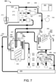
- FIG. 7 shows a schematic view of an embodiment espresso machine similar to FIG.2 , shown having a heated group head 700.
- This embodiment enables a 3 stage progressive heating process for brew water, wherein:
- the heated group head 700 comprises a heating element 710 (typically embedded), thermal cut-out fuse 720, and thermistor 730.
- the brew boiler and group head are typically temperature controlled using proportional-integral-derivative (PID) control module.
- PID proportional-integral-derivative
- a boiler capacity ratio of 10:3 (steam boiler : brew boiler) is utilised .
- a heating element power (wattage) ratio of 10:6: 1 (steam boiler : brew boiler : heated group head) can also be utilised.
- boiler capacity to heating element power (wattage) ratio can be established as follows:
- an optional pressure sensor (or transducer) 740 can be included to monitor water pressure in the flow line 236.
- This sensor 740 is coupled to an MCU (or processor module) to provide a feedback loop operation for controlling a selected pressure to be maintained in real-time, whereby power supplied to the respective pump is varied according to resultant pressure feedback from the sensor and subsequent instructions from the MCU, controller or processor.
- the second flow meter 238 need not be included. It will be appreciated that this adaptation can be applied to other steam control systems (for example the espresso machine 200).
- a removable water tank located at the rear of the machine is typically difficult to obtain regular access for refilling.
- refilling the water tank in situ can result in user error causing overfilling of the tank resulting in potential water ingress issues for the espresso machine body.
- an embodiment espresso machine 800 includes a water fill ingress aperture 810 located on the top or the front (or the front portion of the top) of the machine for relative easy access.
- the aperture 810 may be covered by a hinged door or other lid.
- the water fill aperture is in fluid flow communication with the water tank 820 (typically via an internal horizontal diverter conduit 830 - or funnel).
- Water 812 can be poured through the aperture 810, which progresses first vertically 810, then horizontally through an enlarged accumulator portion and vertically again 832 to a water reservoir 822 in the water tank 820 located adjacent to the base of the machine.
- a maximum volume diversion channel, cavity or conduit 940 provides a fluid overflow path 942 for enabling excess water to be directed vertically into the rear of the drip tray 950 for fluid collection 952.
- the diversion channel is defined by a partial height wall that is located between the reservoir 822 and a front-most wall of the tank 820.
- the diversion channel 940 defines an aperture 944 located within the water tank, at a maximum fill height, for receiving overflow water.
- the diversion channel 940 is at least partially integrally formed with the water tank and directs overflow water, still within the confines of the tank, to the drip-tray 950.
- Using a diversion channel in fluid flow (overflow) communication with a drip tray mounted at the front of an espresso machine body can reduce risk of ingress of water into the espresso machine components during water filling operation, while providing visual (and preferably audible) feedback to the user for establishing completion of the water filling operation. This can enable refilling of the water tank from the top of the espresso machine.
- an espresso machine comprises:
- An unsecured water tank can move due to vibration caused by operation of the machine causing the tank to at least partially disengage from the espresso machine.
- the water tank is typically in fluid flow communication with the espresso machine boilers by way of a releasable valve coupling.
- the release valve restricts fluid flow from the water tank during removal of the tank (typically during filling and/or cleaning).
- a partially engaged/disengaged connection between the water tank and boiler can result in leakage, lower brew pressure during operation, or restriction of water flow from the water tank to the boiler.
- a locking assembly can be incorporated to enable secure engagement between the water tank and espresso machine body.
- the locking assembly can restrict unintentional or undesired disengagement of the water tank from the espresso machine body.
- FIG. 10 shows a perspective rear view of an embodiment espresso machine 1000, showing an aperture 1010 for receiving a water tank.
- a releasable valve coupling element 1020 is adapted to receive a release valve (not shown).
- a lock abutment surface 1030 is adapted for engaging a lock assembly operatively associated with the water tank.
- the water tank assembly is fitted to the espresso machine body in a substantially horizontal direction.
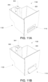
- FIG. 11A, FIG. 11B , FIG. 12A and FIG. 12B show an embodiment water tank assembly 1100 comprising:
- FIG. 11A shows the water tank 1100 having the lock assembly in a locked configuration
- FIG. 11B shows the water tank 1100 having the lock assembly in an unlocked configuration.
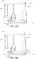
- FIG. 12A shows a partial sectional side view of an espresso machine, shown with the water tank in the engaged configuration.
- the lock assembly 1110 is in the locked configuration
- the release valve 1120 is in the open engaged configuration for enabling fluid flow from the tank.
- FIG. 12B shows a partial sectional side view of an espresso machine, shown with the water tank in the disengaged configuration.
- the lock assembly 1110 is in the unlocked configuration
- the release valve 1120 is in the closed sealed configuration for restricting fluid flow from the tank, best shown in FIG.14B
- FIG. 13A and FIG. 13B engaging of the water tank 1310 with the espresso machine body 1320, brings the a lock assembly 1330 proximal to a lock abutment surface 1340.
- the lock assembly handle can be rotated to a locked configuration (as best shown in FIG. 13 A) , wherein a camming lobe 1332 engages a camming abutment surface 1342 for defining an over centre locked configuration.
- rotation of the lock assembly (about pin 1344) disengages the a camming lobe 1332 from the camming abutment surface 1342 to define an unlocked configuration that enables the water tank to be withdrawn.
- the over-centre cam configuration can restrict unintentional or undesired disengagement of the water tank from the espresso machine body.
- the camming engagement draws the tank into the espresso machine body to the engaged configuration, and the over-centre cam configuration (whereby the axis of rotation defined by the pin 1344 is above the abutment surface) restricts unintentional or undesired disengagement of the locking assembly.
- FIG. 14A and FIG. 14B engaging of the water tank 1410 with the espresso machine body 1420 brings the release valve assembly 1430 into engagement with a releasable valve coupling element 1440.
- a spring biased release valve 1434 engages an abutment surface 1442 and moving the valve to an open engaged configuration for enabling fluid flow from the tank.
- the release valve assembly 1430 is moved away from the with valve coupling element 1440, causing the spring biased release valve 1434 to disengage the abutment surface 1442 and moving the valve to a closed disengaged configuration for restricting fluid flow from the tank.
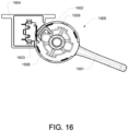
- FIG. 15 through FIG. 17 show, by way of example only, an embodiment steam control apparatus for an espresso machine.
- an espresso machine can comprises a steam wand 1500 that pivots about a ball joint 1501. Steam is delivered to the wand 1500 via the output port 1502 of a valve 1503. Rather than utilising a multi-turn needle valve, some embodiments utilise a continuously variable output ball valve 1504 to regulate the amount of steam delivered (continuously from no steam to full steam) to the steam wand 1500.
- the ball valve 1504 is mechanically operated and mechanically coupled to a rotating paddle 1505 for more authoritative user control. Because the ball valve only needs preferably about 90 degrees of rotation (or at least less than 180 degrees) to go from fully closed to fully open, the user operated paddle 1505 only preferably needs to move through 90 degrees or less to effect full control over the output of the wand 1500.
- the inlet port 1506 receives steam from a steam boiler (for example, a steam boiler 260 as shown in FIG. 2 and FIG. 7 ).
- the ball valve 1504 is within the external housing 1507 of the espresso machine.
- the rotating paddle 1505 consists of a lever hub 1508 that carries a radially extending paddle or lever 1601.
- the lever 1601 provides a convenient grip and a way for the user to apply more torque (accurately) to the valve 1503.
- the hub carries an external cover 1509 in which is formed a slot 1701 through which extends the lever 1601.
- the hub 1508 also has a longitudinal extension in the form a hollow shaft 1510 through which is inserted a fastener 1511 that connects the shaft 1510 to the rotating element of the valve 1504, in this example, a ball valve.
- an interior (or interior facing portion) of the hub 1508 is formed as, or carries, a cam surface 1602.
- the cam surface 1602 cooperates with a micro switch 1603 that may be located within a mounting bracket or housing 1604.
- the cam surface 1602 is adapted to bear against the micro switch 1603 and thereby activate it when the lever 1601 is rotated into a position that allows the valve to deliver steam through the wand 1500.
- the micro switch 1603 can deliver to the espresso machine's MCU, a data (or logging) signal that can be used by the MCU for a variety of purposes.
- the MCU will recognise the output of the micro switch as being indicative that the output of the steam wand is in fluid communication with a steam boiler. This being an undesirable condition, the MCU will either prevent the steam boiler from heating or will block the output to the steam wand until the situation is rectified by the user.
- both the cam surface 1602 and micro switch 1605 are internal to the housing 1507.
- a steam control apparatus for an espresso machine comprises:
- the steam control apparatus includes a switch sensor element for providing a data (or lodging) signal to a computing module.
- the data signal can be indicative for the apparatus being in a fully open configuration wherein output of the steam wand is in fluid communication with a steam boiler.
- an espresso machine 1800 comprises a pump 1801 that draws water from a water tank 1802 and supplies it to a steam boiler 1803. Steam from the boiler 1804 is supplied to a solenoid activated valve 1805. The three way two position solenoid valve 1805 is used to start and stop the flow of steam from the boiler 1803 to the wand 1811.
- a large majority of the wand assembly is constructed in plastic so as to isolate the universal heat in the nozzle 1812. The temperature of the nozzle being monitored by the thermistor 1813 and being generally representative at the temperature of the liquid or milk surround the nozzle 1812.
- the solenoid 1805 When the solenoid 1805 is closed, it allows the steam path to have an open flow path to the atmosphere . Exposing the steam flow path to the atmosphere prevents milk from being siphoned back into the wand 1811 and the venturi 1806. Milk in these areas can cause contamination, foul odours and blockages.
- the valve 1805 is adapted to supply either unadulterated steam from the boiler 1803, or to allow flow of atmosphere to the venturi.
- the venturi 1806 is also supplied with air, preferably pressurized air 1807 that is supplied from an air pump 1808.
- the supply of air from the air pump 1808 passes through a one way valve 1809. A blockage in the steam wand 1811 can cause back pressure in the steam path that can potentially damage the air pump 1808.
- the check valve 1809 prevents damaging back pressure events from adversely effecting the air pump 1808.
- the output 1810 of the venturi is supplied to a steam wand 1811.
- the steam wand 1811 has an output steam nozzle 1812 having attached to or adjacent to it or associated with it a thermistor such as an NTC thermistor 1813.
- a rotating steam lever 1814 activates switches such as micro switches 1815, 1816.
- One of the micro switches 1815 modulates the automatic steam generation process.
- the other micro switch 1816 is used to govern manual steaming operations.
- the state of the switches 1815, 1816 is monitored by a micro processor control unit (MCU) 1817.
- MCU micro processor control unit
- the MCU also reads the output of the thermistor 1813 and serves to control the air pump 1808 and solenoid activated valve 1805.
- the MCU also detects a signal from a third microswitch 1818 that is controlled in accordance with the position of the steam wand 1811.
- the micro switch adjacent the steam wand 1818 detects when the steam wand 1811 has returned to an upright or home position and is thus in a position that is compatible with a purging of the steam wand, in particular an automatic purging as will be explained.
- a user momentarily activates the lever 1814 so that a first micro switch 1815 is contacted.
- the steam wand 1814 acts against a spring or other resilient bias 1819 so that the lever returns to its original, neutral position when released.
- the signal from the micro switch 1815 (or lack of signal) detected by the micro processor 1817 causes the solenoid valve 1805 to open and let steam from the boiler 1804 to flow the venturi 1806.
- steam from the boiler is mixed with air 1807 from the pump 1808.
- the steam air mixture travels through the steam wand 1811 and exits the nozzle 1812 directly into a container 1820, preferably containing milk.
- the temperature sensor 1813 measures the temperature andtransmits the relevant signal to the MCU 1817.
- the MCU then causes the display of the milk temperature 1821.
- the display 1821 is located on a front panel of the espresso machine or stand alone milk frothing device.
- the milk temperature can be preset by the user using a separate control located in an interface.
- both the solenoid 1805 and the air pump 1808 are disabled or deactivated.
- the solenoid 1805 is deactivated, the steam passageway to the wand 1811 is open to the atmosphere 1805.
- the air pump can act independently such that it can activate and deactivate according to a preset temperature, time and or combined logic.
- the user activates the steam lever 1814 in an opposite direction and against the second micro switch 1816.
- This causes the solenoid 1805 to open and lets steam flow from the boiler 1804 flow to the venturi.
- steam passes directly through the venturi and air 1805 is not introduced into the steam passageway.
- Steam travels through the steam wand 1911 and exits the nozzle 1812 directly into the container 1820.
- the temperature sensor 1813 measures the temperature of the milk in the container 1820 and then appropriate signal is transmitted to the micro processor 1817.
- the micro processor causes a display 1821 on the body to show the milk temperature.
- the solenoid 1805 is open to the atmosphere. By opening the steam passageway to atmospheric pressure, the condensation of the hot steam in the steam passageway does not cause milk from the container 1820 to be drawn back into the nozzle 1812.
- An alternative semi-automatic operation - a user can select a (factory pre-set or custom) temperature, such that when a user froths milk, a sensor recognises and/or calculates an approach of user selected temperature and indicates to the user via audio and or visually displayed feedback to switch off the steam delivery.
- a sensor recognises and/or calculates an approach of user selected temperature and indicates to the user via audio and or visually displayed feedback to switch off the steam delivery.
- the wand position micro switch 1818 will identify when the wand has returned to the "home" or safely down position.
- the signal from the micro processor 1818 will be detected by the MCU 1817 and will cause the solenoid 1805 to open for short bursts (e.g. 1 second) or a series of short burst for the purpose of clearing the opening in the nozzle 1812.
- This can be an automatic function to purge the line of frothing debris.
- an audible or visual warning may precede this function to alert the user that steam will be ejected from the nozzle 1812.
- the presence of the wand position sensor switch or micro switch 1818 allows other automated functions to be performed when the steam wand is in a home or fully down position.
- the flow or rate of delivery of air from the air pump 1808 can be controlled, for example, by pulse width modulation. This rate of air flow can be controlled by the user through the user interface 1822.
- the control of the output of the air pump 1808 has the effect of determining the texture of the frothed milk produced in the container 1820. A high flow rate will create a more textured or airy foam whereas a low flow rate will result in a denser, less textured foam.
- a pressure sensor 1830 can be use in enabling the processor MCU 1817 to monitor the steam pressure at the steam wand 1811.
- the pressure sensor is coupled to steam path between the venturi 1806 and steam wand 1811. It would be appreciated that this enables: detection of the steam wand being partially or fully blocked (typically due to a build up of residue in steam wand outlets), which would enable the MCU to stop the steam function and/or alert user of problem; and providing live/real-time feedback of combined steam/air pressure for allowing the MCU to control that air pump flow rate to achieve a preset pressure parameter.
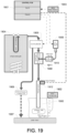
- the temperature of the liquid being steamed in the jug 1900 can be communicated to the input of the control PCB 1901 wirelessly.
- the jug 1900 includes a thermistor such as an NTC thermistor and a transponder 1902 such as an RFID, Wifi, bluetooth or infrared transponder.
- the transponder 1902 emits a wireless (or other radio frequency) signal that is received by a cooperating receiver chip or base station 1903.
- the receiver or base station 1903 supplies the appropriate signal to the input of the PCB1901.
- the steaming device depicted in Figure 19 includes a steam boiler 1904 that supplies steam to a 3/2 solenoid 1905.
- the solenoid controls the flow of steam into the venturi 1908 while simultaneously allowing for overflow or excess pressure to be discharged to the atmosphere 1906, particularly contemplating discharge into the drip tray 1907 that is located below the jug 1900.
- the venturi receives air or pressurized air from an air pump 1909.
- a protective one way valve 1910 is interposed between the air pump and the venturi suction inlet 1911.
- the steam wand is associated with a steam wand position sensor 1912.
- the position sensor 1912 supplies a signal to the control PCB 1901.
- the control PCB 1901 When engaging in manual steaming operations, the control PCB 1901 will allow steam to be discharged through the solenoid 1905 when the wand is in any position.
- the PCB 1901 will only allow the solenoid 1905 to operate when the steam wand is in a specified (the "down") position, as determined by the position sensor 1912.
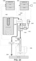
- some embodiments of the invention require the primary steam solenoid 2000 to be controlled jointly or simultaneously or otherwise in a slave relationship with the air pump 2001.
- the onset of the operation of the air pump can be delayed relative to the onset of the steam flow.
- a single output 2002 from the control PCB 2003 is used to control the on and off operation of both the solenoid 2000 and the air pump 2001.
- a manually operated valve such as a ball valve 2100 is used to provide the user with control over the steam output of the steam boiler 2101. Steam flowing through the ball valve 2100 is delivered to the venturi 2102.
- An anti-siphon or anti-vacuum valve 2103 is interposed between the ball valve 2100 and the venturi 2102. The anti-vacuum valve 2103 prevents vacuum pressure above the venturi from allowing ingress of fluid into the ball valve, boiler or other aspects of the machine that are upstream from the valve 2103.
- the ball valve 2100 is associated with a sensor 2104. The sensor transmits the operative position of the ball valve of the control PCB 2105.
- the control PCB can use this information to illuminate a warning light 2106 on an exterior surface of the steaming or espresso making machine that indicates, for example, that the steam pathway to the wand is open.
- a warning light 2106 on an exterior surface of the steaming or espresso making machine that indicates, for example, that the steam pathway to the wand is open.
- the control PCB 2105 will now allow power to be delivered to the steam boiler 2101. This prevents inadvertent operation of the boiler when first turning on the machine and the ball valve 2100 is open.
- a multi-ported ceramic valve 2200 may be used in place of the ball valve 2100 depicted in Figure 21 .
- the ceramic valve provides additional flexibility by allowing for numerous different flow pathways to be controlled from a single rotating valve stem, being the valve stem associated with the ceramic valve 2200.
- the ceramic style valve 2200 can incorporate an overflow discharge port 2201 that leads to an overflow pathway 2202 that discharges either to atmosphere 2203 or more particularly to the drip tray 2204 that lies below the jug 1900.
- the rotating ceramic style valve 2200 can also incorporate a manual bypass flow path 2205 that allows steam from the boiler 2101 to bypass the venturi 1908. Because the venturi is essentially a restriction in the flow path, the manual bypass flow path 2205 is capable of delivering a greater volume of steam to the steam wand 2210.
- two separate control PCBs 2300, 2301 are used in the control of the primary steam solenoid 2302 and the air pump 2303 that delivers air to the venturi 2304.
- a pressure detecting sensor or switch 2305 detects pressure in the line 2306 between the solenoid 2302 and the venturi 2304. When the pressure sensor or switch detects the presence of pressure, a signal is sent to the input of the second PCB 2301. The second PCB 2301 interprets that signal as a command to supply power to the air pump 2303.
- the pressure switch 2305 is not required.
- a user operated control 2310 provides the second control PCB 2301 with a signal or switch state that is interpreted as a command to supply power to the air pump 2303. If required, the user operated switch 2310 can be disabled in other ways when the primary solenoid 2302 is closed.
- the one or more processors operate as a standalone device or may be connected, e.g., networked to other processor(s), in a networked deployment, the one or more processors may operate in the capacity of a server or a client machine in server-client network environment, or as a peer machine in a peer-to-peer or distributed network environment.
- processor may refer to any device or portion of a device that processes electronic data, e.g., from registers and/or memory to transform that electronic data into other electronic data that, e.g., may be stored in registers and/or memory.
- a "computer” or a “computing machine” or a “computing platform” may include one or more processors.
- the methodologies described herein are, in one embodiment, performable by one or more processors that accept computer-readable (also called machine-readable) code containing a set of instructions that when executed by one or more of the processors carry out at least one of the methods described herein. Any processor capable of executing a set of instructions (sequential or otherwise) that specify actions to be taken is included.
- Coupled when used in the claims, should not be interpreted as being limitative to direct connections only.
- the terms “coupled” and “connected”, along with their derivatives, may be used. It should be understood that these terms are not intended as synonyms for each other.
- the scope of the expression a device A coupled to a device B should not be limited to devices or systems wherein an output of device A is directly connected to an input of device B. It means that there exists a path between an output of A and an input of B which may be a path including other devices or means.
- Coupled may mean that two or more elements are either in direct physical or electrical contact, or that two or more elements are not in direct contact with each other but yet still co-operate or interact with each other.
Landscapes
- Engineering & Computer Science (AREA)
- Food Science & Technology (AREA)
- Mechanical Engineering (AREA)
- Apparatus For Making Beverages (AREA)
- Tea And Coffee (AREA)
Applications Claiming Priority (5)
| Application Number | Priority Date | Filing Date | Title |
|---|---|---|---|
| AU2011901751A AU2011901751A0 (en) | 2011-05-10 | Water Handling in a Coffee Maker | |
| AU2011903195A AU2011903195A0 (en) | 2011-08-11 | Steam Control in a Coffee Maker | |
| AU2012900647A AU2012900647A0 (en) | 2012-02-21 | Improved Steam Control in a Coffee Maker | |
| EP12782726.9A EP2709500B1 (de) | 2011-05-10 | 2012-05-10 | Vorrichtung und verfahren für eine verbesserte kaffeemaschine |
| PCT/AU2012/000501 WO2012151629A1 (en) | 2011-05-10 | 2012-05-10 | Apparatus and method for an improved coffee maker |
Related Parent Applications (1)
| Application Number | Title | Priority Date | Filing Date |
|---|---|---|---|
| EP12782726.9A Division EP2709500B1 (de) | 2011-05-10 | 2012-05-10 | Vorrichtung und verfahren für eine verbesserte kaffeemaschine |
Publications (2)
| Publication Number | Publication Date |
|---|---|
| EP4275559A2 true EP4275559A2 (de) | 2023-11-15 |
| EP4275559A3 EP4275559A3 (de) | 2024-01-24 |
Family
ID=47138568
Family Applications (2)
| Application Number | Title | Priority Date | Filing Date |
|---|---|---|---|
| EP23200706.2A Pending EP4275559A3 (de) | 2011-05-10 | 2012-05-10 | Vorrichtung und verfahren für eine verbesserte kaffeemaschine |
| EP12782726.9A Active EP2709500B1 (de) | 2011-05-10 | 2012-05-10 | Vorrichtung und verfahren für eine verbesserte kaffeemaschine |
Family Applications After (1)
| Application Number | Title | Priority Date | Filing Date |
|---|---|---|---|
| EP12782726.9A Active EP2709500B1 (de) | 2011-05-10 | 2012-05-10 | Vorrichtung und verfahren für eine verbesserte kaffeemaschine |
Country Status (6)
| Country | Link |
|---|---|
| US (1) | US20140069279A1 (de) |
| EP (2) | EP4275559A3 (de) |
| CN (6) | CN109588984B (de) |
| AU (7) | AU2012253224B2 (de) |
| RU (2) | RU2737062C9 (de) |
| WO (1) | WO2012151629A1 (de) |
Families Citing this family (84)
| Publication number | Priority date | Publication date | Assignee | Title |
|---|---|---|---|---|
| US10383474B2 (en) * | 2011-05-10 | 2019-08-20 | Breville Pty Limited | Coffee machine with overflow feature |
| ITTO20130074A1 (it) * | 2013-01-30 | 2014-07-31 | Indesit Co Spa | Macchina da caffe' di tipo elettrodomestico |
| EP2950689A2 (de) * | 2013-01-30 | 2015-12-09 | Indesit Company S.p.A. | Haushaltskaffeemaschine |
| ITBS20130037A1 (it) | 2013-03-21 | 2014-09-22 | Bsh Italia S R L | Macchina da caffe' |
| US9364116B2 (en) * | 2013-04-11 | 2016-06-14 | Modbar, Llc | Modular beverage making and dispensing apparatus |
| WO2015028592A1 (en) * | 2013-08-30 | 2015-03-05 | Norgren Ag | Fluid flow control device |
| CN110840261B (zh) * | 2013-09-30 | 2022-10-18 | 布瑞威利私人有限公司 | 适于与壶配合使用的起泡装置 |
| USD742169S1 (en) * | 2013-10-07 | 2015-11-03 | Breville Pty Limited | Espresso making machine |
| ITRE20130084A1 (it) * | 2013-11-15 | 2015-05-16 | Ind Societa Cooperati Va Coop | Macchina per la preparazione di bevande |
| EP3107434B1 (de) * | 2014-02-20 | 2020-01-22 | CMA Macchine per caffè S.r.l. | Kaffeemaschine und zugehöriges steuerungsverfahren |
| AU2015202472A1 (en) * | 2014-05-09 | 2015-11-26 | Sunbeam Corporation Pty Ltd | Espresso machine |
| FR3021198B1 (fr) * | 2014-05-23 | 2016-05-13 | Seb Sa | Dispositif et procede de production et de distribution de liquide en ebullition et appareil de preparation de boisson equipe d'un tel dispositif |
| WO2016000094A1 (en) * | 2014-06-06 | 2016-01-07 | Whirlpool Corporation | Microwave oven with steam generating device |
| US11051649B2 (en) | 2014-06-17 | 2021-07-06 | Sharkninja Operating Llc | Automatic coffee maker and method of preparing a brewed beverage |
| US10028615B2 (en) | 2014-06-17 | 2018-07-24 | Sharkninja Operating Llc | Method of brewing coffee |
| CN203987603U (zh) * | 2014-07-09 | 2014-12-10 | 大统营实业股份有限公司 | 咖啡机进水结构 |
| CN104188517B (zh) * | 2014-08-13 | 2017-04-26 | 蔡坚明 | 一种咖啡机 |
| JP2017538504A (ja) * | 2014-12-24 | 2017-12-28 | ネステク ソシエテ アノニム | 飲料調製マシンのインターフェースシステム |
| CN107205580B (zh) * | 2015-01-20 | 2019-10-15 | 松下知识产权经营株式会社 | 饮料供应装置 |
| US10716430B2 (en) * | 2015-02-05 | 2020-07-21 | Coffee Solutions, Llc | Devices and methods for beverage brewer regulation |
| RU2719183C2 (ru) * | 2015-03-30 | 2020-04-17 | Бревилл Пти Лимитед | Сборочный узел датчика температуры устройства вспенивания молока |
| DE102015209986A1 (de) * | 2015-05-29 | 2016-12-01 | BSH Hausgeräte GmbH | Getränkeautomat |
| DE102015209985A1 (de) * | 2015-05-29 | 2016-12-01 | BSH Hausgeräte GmbH | Getränkeautomat |
| NL2015069B1 (en) * | 2015-07-01 | 2017-01-30 | Douwe Egberts Bv | A method of preparing a beverage and a device for preparing a beverage. |
| CN105326394A (zh) * | 2015-10-19 | 2016-02-17 | 珠海格力电器股份有限公司 | 一种饮水机水箱溢水导流结构及饮水机 |
| DE102016202257A1 (de) * | 2016-02-15 | 2017-08-17 | Wmf Group Gmbh | Getränkebereiter, insbesondere Kaffeemaschine, für Festwasseranschluss sowie Festwasserkit |
| CN108366692B (zh) * | 2016-03-07 | 2023-01-06 | 布瑞威利私人有限公司 | 蒸汽棒 |
| CN105919431B (zh) * | 2016-06-24 | 2018-12-07 | 通用国际企业有限公司 | 一种咖啡机冲泡压力的控制方法及其系统 |
| GB201614478D0 (en) * | 2016-08-25 | 2016-10-12 | Nicoventures Holdings Ltd | Control circuit for a vapour provision system |
| CN107049023B (zh) * | 2016-11-17 | 2023-05-30 | 上海宝路通咖啡机有限公司 | 咖啡机酿造系统 |
| US11470998B2 (en) * | 2017-01-10 | 2022-10-18 | Nuwave, Llc | Automatic beverage maker reservoir heating system |
| CN110785108B (zh) * | 2017-05-12 | 2023-08-04 | 纽威澳大利亚有限公司 | 具有定量机构的浓缩咖啡机 |
| EP3403548A1 (de) * | 2017-05-18 | 2018-11-21 | Jura Elektroapparate AG | Brühvorrichtung zum zubereiten eines heissgetränks und zugehöriges verfahren |
| RU2763306C2 (ru) * | 2017-06-22 | 2021-12-28 | Сосьете Де Продюи Нестле С.А. | Устройство для приготовления напитка с насосом с ручным управлением и со средствами управления потоком |
| EP3685672A1 (de) | 2017-07-11 | 2020-07-29 | NuBru, LLC | Verfahren und vorrichtung zur verbesserung der konsistenz von espresso-shots |
| CH714003B1 (de) * | 2017-07-20 | 2022-05-13 | Steiner Ag Weggis | Verfahren zum manuellen Steuern einer Bedieneinheit für die Abgabe von Dampf aus einer Kaffeemaschine, sowie eine Bedieneinheit. |
| DE102017217953A1 (de) * | 2017-10-09 | 2019-04-11 | Wmf Group Gmbh | Getränkebereiter und Verfahren zur Bestimmung von durch einen Getränkebereiter ausgegebenen und/oder in diesem zur Getränkebereitung verwendeten Heißwassermengen |
| CN121369929A (zh) * | 2017-11-07 | 2026-01-23 | 布瑞威利私人有限公司 | 制作饮料的设备和相关联方法以及功率管理系统 |
| CN107831798B (zh) * | 2017-11-15 | 2021-08-06 | 无锡鼎加弘思饮品科技有限公司 | 利用流量计脉冲实现压力控制的预警系统及预警方法 |
| CN108175279B (zh) * | 2017-12-29 | 2020-11-06 | 王德涛 | 一种咖啡冲泡方法 |
| CN108125564B (zh) * | 2017-12-29 | 2020-06-30 | 王德涛 | 一种咖啡机 |
| EP3536201A1 (de) * | 2018-03-09 | 2019-09-11 | Reneka International | Vorrichtung zur erzeugung von dampf und druckluft, und steuerverfahren einer solchen vorrichtung |
| WO2019190300A1 (es) * | 2018-03-28 | 2019-10-03 | Sanchez Arreola Fabian | Máquina para preparar bebidas calientes |
| CN108742148A (zh) * | 2018-05-06 | 2018-11-06 | 张连民 | 智能功夫茶具 |
| CN109124354B (zh) * | 2018-08-06 | 2021-06-11 | 上海机商实业有限公司 | 咖啡萃取装置、咖啡机及自动咖啡售卖机 |
| JP6635162B1 (ja) * | 2018-09-14 | 2020-01-22 | 富士電機株式会社 | 飲料供給装置 |
| IT201800010697A1 (it) * | 2018-11-29 | 2020-05-29 | Simonelli Group Spa | Macchina da caffè con sistema di preinfusione proporzionale. |
| WO2020112067A2 (en) * | 2018-11-29 | 2020-06-04 | GÜRER, Çetin | A device that distributes coffee homogenously and applies controlled and measurable pressure |
| EP3669715A1 (de) | 2018-12-17 | 2020-06-24 | Koninklijke Philips N.V. | Kaffeemaschine |
| GB2580183B (en) * | 2018-12-24 | 2022-11-30 | Douwe Egberts Bv | A system and method for heating and frothing a beverage |
| US11337548B2 (en) * | 2019-06-06 | 2022-05-24 | B/E Aerospace, Inc. | Pressure sensor overflow interlock system for beverage maker |
| US11540663B2 (en) * | 2019-06-06 | 2023-01-03 | B/E Aerospace, Inc. | Differential pressure flow meter for beverage maker |
| US11529015B2 (en) * | 2019-06-06 | 2022-12-20 | B/E Aerospace, Inc. | Beverage maker platen overflow sensing system |
| IT201900009249A1 (it) * | 2019-06-17 | 2020-12-17 | Gruppo Cimbali Spa | Apparato per la montatura del latte e metodo per la montatura del latte mediante tale apparato |
| CN112678899B (zh) * | 2019-10-18 | 2022-05-31 | 佛山市顺德区美的饮水机制造有限公司 | 净水设备 |
| DE102019216063B4 (de) | 2019-10-18 | 2024-08-29 | Bellezza Milano S.R.L. | Brühgruppe für eine elektrisch arbeitende Espressomaschine und Espressomaschine |
| CN112678897B (zh) * | 2019-10-18 | 2022-05-27 | 佛山市顺德区美的饮水机制造有限公司 | 净水设备 |
| CN112678898B (zh) * | 2019-10-18 | 2022-05-27 | 佛山市顺德区美的饮水机制造有限公司 | 净水设备 |
| GB2590904B (en) * | 2019-12-16 | 2023-05-03 | Giocoguado Ltd | Coffee-making apparatus, valve and adapter plate |
| CA3159897A1 (en) | 2019-12-16 | 2021-06-24 | Societe Des Produits Nestle S.A. | Beverage machine with an off-set actuator |
| PL3841937T3 (pl) * | 2019-12-27 | 2024-03-18 | Koninklijke Philips N.V. | Ekspres do kawy z układem zaworów |
| CN111110044A (zh) * | 2020-01-08 | 2020-05-08 | 东莞厚街赤岭通用电器制造有限公司 | 一种分段压力调节咖啡机及其咖啡冲泡方法 |
| US12180056B2 (en) | 2020-02-21 | 2024-12-31 | Bartrack, Inc. | Monitoring equilibrium and dispensement of a fluid dispensement system to improve quality and efficiency |
| EP3878325B1 (de) * | 2020-03-10 | 2023-11-15 | Rocket Milano S.r.L. | Maschine zur ausgabe von espressokaffee und dampf und verfahren zur steuerung dieser maschine |
| IT202000008128A1 (it) * | 2020-04-16 | 2021-10-16 | De Longhi Appliances Srl | Macchina da caffè |
| EP4188166A1 (de) * | 2020-07-29 | 2023-06-07 | Société des Produits Nestlé S.A. | Getränkezubereitungsmaschine mit maschinengehäuse und abnehmbarem flüssigkeitstank |
| DE102020130422A1 (de) * | 2020-11-18 | 2022-05-19 | Melitta Professional Coffee Solutions GmbH & Co. KG | Heißgetränkeautomat, insbesondere Kaffeevollautomat sowie Verfahren zum Betrieb eines solchen Automaten |
| CA3133297A1 (en) * | 2020-12-02 | 2022-06-02 | Simonelli Group S.P.A. | Steam production system for professional coffee machines |
| CN218528465U (zh) * | 2021-03-24 | 2023-02-28 | 布瑞威利私人有限公司 | 用于浓缩咖啡机的组头 |
| EP4108142B1 (de) * | 2021-06-22 | 2023-08-16 | Simonelli Group S.P.A. | Elektrische espressokaffeemaschine ausgestattet und konzipiert auch amerikanischen kaffee auszugeben |
| USD966770S1 (en) * | 2021-08-17 | 2022-10-18 | Solis of Switzerland AG | Coffee machine |
| MX2024008973A (es) * | 2022-01-28 | 2024-08-20 | Bartrack Inc | Monitoreo del equilibrio y dispensacion de un sistema de dispensacion de fluidos para mejorar la calidad y la eficiencia. |
| USD1036179S1 (en) * | 2022-02-17 | 2024-07-23 | Breville Pty Limited | Coffee machine with tamp chute |
| CN115349754A (zh) * | 2022-05-02 | 2022-11-18 | 宁波麦蒂智能科技有限公司 | 机器人咖啡站 |
| CN115682416A (zh) * | 2022-10-26 | 2023-02-03 | 广东万家乐燃气具有限公司 | 一种带隐式物盘的净饮燃热一体机 |
| USD1063477S1 (en) * | 2023-02-06 | 2025-02-25 | The Steelstone Group Llc | Espresso machine |
| USD1059107S1 (en) | 2023-04-13 | 2025-01-28 | Whirlpool Corporation | Espresso machine |
| IT202300027096A1 (it) * | 2023-12-19 | 2025-06-19 | De Longhi Appliances Srl | Apparato e procedimento di riempimento automatico di un liquido e relativa macchina |
| US12369744B1 (en) | 2024-01-18 | 2025-07-29 | Sharkninja Operating Llc | Preparation of beverage machines for cold beverage brewing |
| WO2025155323A1 (en) | 2024-01-18 | 2025-07-24 | Sharkninja Operating Llc | Preventing coffee bean grinder jamming |
| US12575692B2 (en) | 2024-01-18 | 2026-03-17 | Sharkninja Operating Llc | Suggesting coffee bean grind size for beverage machines |
| DE102024102908A1 (de) * | 2024-02-01 | 2025-08-07 | Stiebel Eltron Gmbh & Co. Kg | Dampf- und Heißwassererzeuger |
| USD1111623S1 (en) * | 2024-02-28 | 2026-02-10 | Breville Pty Limited | Shrouds of a coffee machine |
| WO2026038290A1 (en) | 2024-08-12 | 2026-02-19 | Sanremo Coffee Machines S.R.L. | Coffee machine with limited rotation of its water and steam lances |
Family Cites Families (69)
| Publication number | Priority date | Publication date | Assignee | Title |
|---|---|---|---|---|
| CA921878A (en) * | 1969-12-23 | 1973-02-27 | John A. Gardner, Jr. | Hot liquid dispenser |
| US4007856A (en) * | 1975-07-23 | 1977-02-15 | Refreshment Machinery Incorporated | Apparatus for dispensing water at different temperatures |
| US4138936A (en) * | 1977-05-20 | 1979-02-13 | Rival Manufacturing Company | Coffee brewing machine |
| US4751941A (en) * | 1985-09-26 | 1988-06-21 | Dagma Deutsche Automaten | Hot water tank for use in beverage dispensing machines |
| US5490447A (en) * | 1989-07-05 | 1996-02-13 | Faema S.P.A. | Automatic espresso and cappuccino machine |
| AU5941790A (en) * | 1989-09-06 | 1991-04-18 | Selsys Corporation | Temperature sensing steam wand |
| US4974500A (en) * | 1989-09-29 | 1990-12-04 | Boyd Coffee Company | Hot beverage preparation and dispensing cart |
| US5207148A (en) * | 1990-06-25 | 1993-05-04 | Caffe Acorto, Inc. | Automated milk inclusive coffee apparatus |
| CN2144143Y (zh) * | 1992-09-23 | 1993-10-20 | 宫联慧 | 一种公用建筑小型中水回用装置 |
| US5372061A (en) * | 1993-04-14 | 1994-12-13 | Avanti Espresso U.S.A., Inc. | Espresso/cappuccino apparatus and method |
| CN2306728Y (zh) * | 1996-02-15 | 1999-02-10 | 广州图强电器厂 | 快热式全自动电开水器 |
| WO1998027854A1 (en) * | 1996-12-23 | 1998-07-02 | Koninklijke Philips Electronics N.V. | Coffee maker |
| JP2929285B1 (ja) * | 1998-01-26 | 1999-08-03 | 株式会社日本イトミック | 貯湯式電気湯沸器 |
| NL1010554C2 (nl) * | 1998-10-07 | 2000-04-10 | Bravilor Holding Bv | Apparaat voor het bereiden van een drank. |
| CN2389880Y (zh) * | 1999-10-13 | 2000-08-02 | 朱国柱 | 用浮漂阀控制纯净水进水的纯净水机 |
| IN192798B (de) * | 2000-03-15 | 2004-05-22 | Fianara Int Bv | |
| JP2002026555A (ja) * | 2000-07-04 | 2002-01-25 | Sony Corp | 電子装置における放熱機構 |
| ES2220887T3 (es) * | 2001-11-14 | 2004-12-16 | Cafina Ag | Dispositivo de espumado de leche y de calentamiento de leche. |
| AU2002309254A1 (en) * | 2002-05-06 | 2003-11-17 | Cimbali, S.P.A. | Device for heating and working up milk |
| US7021206B2 (en) * | 2002-06-18 | 2006-04-04 | Eckenhausen Roland B | Hot dairy-based beverage dispenser |
| DE20300851U1 (de) * | 2003-01-21 | 2004-05-27 | Wik Far East Ltd. | Vorrichtung zum Aufschäumen eines Getränkes sowie Kaffeeautomat mit einer solchen Vorrichtung |
| WO2004071258A2 (en) * | 2003-02-06 | 2004-08-26 | Edgecraft Corporation | Improved apparatus for brewing beverages |
| ITTO20030271A1 (it) * | 2003-04-09 | 2004-10-10 | Rancilio Macchine Caffe | Dispositivo erogatore automatico di vapore per la preparazione di bevande calde e/o schiumate. |
| US7550169B2 (en) * | 2003-07-08 | 2009-06-23 | The Coca-Cola Company | System and method for producing foamed and steamed milk from milk concentrate |
| JP2005128751A (ja) * | 2003-10-23 | 2005-05-19 | Toshiba Electric Appliance Co Ltd | 飲料ディスペンサ装置の排水装置 |
| US7523695B2 (en) * | 2003-12-12 | 2009-04-28 | Keurig, Incorporated | System for dispensing metered volumes of heated water to the brew chamber of a single serve beverage brewer |
| CN2675006Y (zh) * | 2004-02-20 | 2005-02-02 | 陈锦沛 | 带电控水龙头的饮水机 |
| DE102004025038A1 (de) * | 2004-05-18 | 2005-12-08 | Eimer, Klaus, Dipl.-Ing. | Vorrichtung zum Aufschäumen von Milch mit externer Milchansaugung |
| DE602005002145T2 (de) * | 2004-06-25 | 2008-05-15 | Arcelik Anonim Sirketi | Kaffeemaschine |
| DE102004056224A1 (de) * | 2004-11-19 | 2006-05-24 | Tchibo Gmbh | System mit einer Kaffeemaschine und einer Portionskapsel |
| JP4397341B2 (ja) * | 2005-04-01 | 2010-01-13 | 三洋電機株式会社 | ミルクフォーマー |
| DE602005007475D1 (de) * | 2005-06-07 | 2008-07-24 | Nestec Sa | Getränkemaschine mit Auffangwanne für Behälter unterschiedlicher Höhe |
| CN2839338Y (zh) * | 2005-09-12 | 2006-11-22 | 佛山市三水合成塑胶五金制品有限公司 | 电熨器蒸汽控制装置 |
| EP2066971B1 (de) * | 2005-12-19 | 2020-06-17 | Koninklijke Philips N.V. | Vorrichtung und verfahren zum erzeugen von dampf |
| NZ577054A (en) * | 2006-03-28 | 2011-08-26 | Tuttoespresso Spa | Process and apparatus for preparing a beverage under controlled pressure |
| CN200965388Y (zh) * | 2006-06-13 | 2007-10-24 | 上海亿悦电器科技有限公司 | 一种节能降耗型快速加热直饮机 |
| ITUD20060154A1 (it) * | 2006-06-14 | 2007-12-15 | Illycaffe Spa | Macchina per la produzione di bevande a base di acqua e relativo metodo |
| US20110163116A1 (en) * | 2006-07-14 | 2011-07-07 | Charles Dixon | Bottled water dispenser |
| CN200942037Y (zh) * | 2006-07-17 | 2007-09-05 | 安徽开聪信息科技有限公司 | 水开智能提示装置 |
| US8544380B2 (en) * | 2006-08-23 | 2013-10-01 | Bunn-O-Matic Corporation | Beverage brewing system including a liquid moving assembly |
| PL2345355T3 (pl) * | 2006-12-06 | 2013-10-31 | Rheavendors Services Spa | Sposób i maszyna do wytwarzania i dozowania napojów |
| EP1932457A1 (de) * | 2006-12-11 | 2008-06-18 | Nestec S.A. | Gerät und Verfahren zur Herstellung einer schäumenden Flüssigkeit aus löslichen Inhaltstoffen und Verdünnungsmittel |
| DE602007000812D1 (de) * | 2007-01-23 | 2009-05-14 | Rancilio Macchine Caffe | Vorrichtung zum Erhitzen und/oder Aufschäumen eines Getränks |
| JP4956212B2 (ja) * | 2007-02-08 | 2012-06-20 | 三洋電機株式会社 | 飲料ディスペンサ |
| JP2010519688A (ja) * | 2007-02-16 | 2010-06-03 | コーニンクレッカ フィリップス エレクトロニクス エヌ ヴィ | 液体フロースルーヒーターの制御 |
| AU2008202438B2 (en) * | 2007-06-06 | 2014-08-21 | Sunbeam Corporation Pty Ltd | Espresso machine |
| DE102007035939B4 (de) * | 2007-07-31 | 2017-10-26 | De'longhi S.P.A. | Vorrichtung für die Bildung von Schaum in einem milchhaltigen Getränk |
| EP2025270B1 (de) * | 2007-08-16 | 2017-04-12 | Cafina AG | Vorrichtung zum Aufschäumen und Erhitzen von Milch |
| CN101380198A (zh) * | 2007-09-07 | 2009-03-11 | 黄海斌 | 煮泡装置 |
| CN201119773Y (zh) * | 2007-09-12 | 2008-09-24 | 邝坚 | 咖啡机增压泄压阀 |
| FR2929089B1 (fr) * | 2008-03-26 | 2010-04-02 | Seb Sa | Procede de nettoyage d'une buse vapeur d'une machine pour la preparation de boissons |
| EP2127734A1 (de) * | 2008-05-28 | 2009-12-02 | Nestec S.A. | Mischanordnung mit Mischkammer und Überlaufkammer sowie Mischverfahren |
| CN101601546A (zh) * | 2008-06-10 | 2009-12-16 | 康奈尔公司 | 改进的咖啡机 |
| CN101332043B (zh) * | 2008-08-01 | 2011-05-18 | 晶辉电器(深圳)有限公司 | 饮水机 |
| CN201239007Y (zh) * | 2008-08-23 | 2009-05-20 | 李琼心 | 一种防回流蒸汽烹调装置 |
| CN102137610B (zh) * | 2008-09-01 | 2014-09-17 | 雀巢产品技术援助有限公司 | 用于调制奶基液体的器具 |
| CN101387395B (zh) * | 2008-10-17 | 2011-11-30 | 陈高永 | 一种蒸汽发生装置 |
| CN201365830Y (zh) * | 2009-01-19 | 2009-12-23 | 傅永旺 | 双胆双控步进式饮水机 |
| WO2010121299A1 (en) * | 2009-04-20 | 2010-10-28 | Sunbeam Corporation Limited | Steam wand |
| CN201404073Y (zh) * | 2009-04-28 | 2010-02-17 | 漳州灿坤实业有限公司 | 一种无线传输温度式电水壶 |
| CN201445353U (zh) * | 2009-07-10 | 2010-05-05 | 黄伟聪 | 一种可远程控制的网络电水壶 |
| IT1396821B1 (it) * | 2009-10-22 | 2012-12-14 | Elektra S R L | Metodo di montatura del latte e dispositivo montalatte per attuare il metodo. |
| ATE522169T2 (de) * | 2009-10-23 | 2011-09-15 | Gruppo Cimbali Spa | Kaffeemaschine mit abgabedruckregulierung und damit zusammenhängendes verfahren |
| CN201612505U (zh) * | 2009-12-28 | 2010-10-27 | 浙江苏泊尔家电制造有限公司 | 一种可实现无线控制的电水壶 |
| CN201730011U (zh) * | 2009-12-29 | 2011-02-02 | 松下·万宝(广州)电熨斗有限公司 | 蒸汽电熨斗 |
| CN101849777B (zh) * | 2010-03-29 | 2012-01-18 | 广东新宝电器股份有限公司 | 贮水式咖啡机 |
| RU2571357C2 (ru) * | 2010-05-11 | 2015-12-20 | Бревилл Пти Лимитед | Способ работы кофеварки эспрессо и устройство для его осуществления |
| CN201790578U (zh) * | 2010-08-06 | 2011-04-13 | 汕头市富澜正东自动售货设备有限公司 | 具有改进的透气溢流机构的热饮机 |
| CN102008237B (zh) * | 2010-11-11 | 2012-10-03 | 广东新宝电器股份有限公司 | 多功能咖啡机 |
-
2012
- 2012-05-10 CN CN201811312947.0A patent/CN109588984B/zh active Active
- 2012-05-10 EP EP23200706.2A patent/EP4275559A3/de active Pending
- 2012-05-10 CN CN201610391226.8A patent/CN105942861A/zh active Pending
- 2012-05-10 RU RU2016150659A patent/RU2737062C9/ru active
- 2012-05-10 CN CN201811312948.5A patent/CN109588985A/zh active Pending
- 2012-05-10 RU RU2013154568A patent/RU2607542C2/ru active
- 2012-05-10 CN CN202110384883.0A patent/CN113080706A/zh active Pending
- 2012-05-10 AU AU2012253224A patent/AU2012253224B2/en active Active
- 2012-05-10 CN CN201510965223.6A patent/CN105433800A/zh active Pending
- 2012-05-10 US US14/116,327 patent/US20140069279A1/en not_active Abandoned
- 2012-05-10 CN CN201280022617.2A patent/CN103874439A/zh active Pending
- 2012-05-10 WO PCT/AU2012/000501 patent/WO2012151629A1/en not_active Ceased
- 2012-05-10 EP EP12782726.9A patent/EP2709500B1/de active Active
-
2017
- 2017-01-12 AU AU2017200216A patent/AU2017200216B2/en active Active
-
2018
- 2018-05-22 AU AU2018203581A patent/AU2018203581A1/en not_active Abandoned
- 2018-09-20 AU AU2018232987A patent/AU2018232987B2/en active Active
-
2020
- 2020-12-23 AU AU2020294225A patent/AU2020294225B2/en active Active
-
2023
- 2023-08-18 AU AU2023216873A patent/AU2023216873B2/en active Active
-
2025
- 2025-12-22 AU AU2025283680A patent/AU2025283680A1/en active Pending
Also Published As
| Publication number | Publication date |
|---|---|
| AU2023216873A1 (en) | 2023-09-07 |
| RU2737062C1 (ru) | 2020-11-24 |
| WO2012151629A1 (en) | 2012-11-15 |
| EP2709500B1 (de) | 2023-10-18 |
| US20140069279A1 (en) | 2014-03-13 |
| AU2018203581A1 (en) | 2018-06-14 |
| RU2607542C2 (ru) | 2017-01-10 |
| AU2017200216B2 (en) | 2018-06-21 |
| RU2737062C9 (ru) | 2021-02-04 |
| CN109588984B (zh) | 2026-03-27 |
| EP2709500A1 (de) | 2014-03-26 |
| CN113080706A (zh) | 2021-07-09 |
| EP4275559A3 (de) | 2024-01-24 |
| AU2018232987B2 (en) | 2020-10-08 |
| CN103874439A (zh) | 2014-06-18 |
| AU2017200216A1 (en) | 2017-02-02 |
| AU2025283680A1 (en) | 2026-01-22 |
| AU2020294225B2 (en) | 2023-05-18 |
| CN109588985A (zh) | 2019-04-09 |
| CN105433800A (zh) | 2016-03-30 |
| AU2023216873B2 (en) | 2025-10-02 |
| AU2012253224A2 (en) | 2015-12-10 |
| AU2012253224B2 (en) | 2016-12-01 |
| AU2020294225A1 (en) | 2021-01-28 |
| AU2012253224A1 (en) | 2014-01-09 |
| EP2709500A4 (de) | 2014-12-10 |
| CN105942861A (zh) | 2016-09-21 |
| AU2018232987A1 (en) | 2018-10-11 |
| CN109588984A (zh) | 2019-04-09 |
| RU2013154568A (ru) | 2015-06-20 |
Similar Documents
| Publication | Publication Date | Title |
|---|---|---|
| AU2020294225B2 (en) | Apparatus and method for an improved coffee maker | |
| US20240335062A1 (en) | Coffee machine with overflow feature | |
| EP3188628B1 (de) | Getränkeherstellungsvorrichtung und -verfahren | |
| EP3713457B1 (de) | Maschine und verfahren zur herstellung von getränken | |
| CN105992540A (zh) | 用于使牛奶起泡的装置和方法 | |
| CN114025647B (zh) | 用于制备饮料、优选奶沫或热奶的方法和装置 | |
| RU2831438C2 (ru) | Кружка, предназначенная для использования совместно с устройством подачи пара | |
| ITMI20070131A1 (it) | Procedimento ed apparecchiatura per il riscaldamento a diverse temperature desiderate di un liquido per la formazione di bevande | |
| TW201736783A (zh) | 定溫供水飲料機 |
Legal Events
| Date | Code | Title | Description |
|---|---|---|---|
| PUAI | Public reference made under article 153(3) epc to a published international application that has entered the european phase |
Free format text: ORIGINAL CODE: 0009012 |
|
| STAA | Information on the status of an ep patent application or granted ep patent |
Free format text: STATUS: THE APPLICATION HAS BEEN PUBLISHED |
|
| AC | Divisional application: reference to earlier application |
Ref document number: 2709500 Country of ref document: EP Kind code of ref document: P |
|
| AK | Designated contracting states |
Kind code of ref document: A2 Designated state(s): AL AT BE BG CH CY CZ DE DK EE ES FI FR GB GR HR HU IE IS IT LI LT LU LV MC MK MT NL NO PL PT RO RS SE SI SK SM TR |
|
| REG | Reference to a national code |
Ref country code: DE Ref legal event code: R079 Free format text: PREVIOUS MAIN CLASS: A47J0031440000 Ipc: A47J0031240000 |
|
| PUAL | Search report despatched |
Free format text: ORIGINAL CODE: 0009013 |
|
| AK | Designated contracting states |
Kind code of ref document: A3 Designated state(s): AL AT BE BG CH CY CZ DE DK EE ES FI FR GB GR HR HU IE IS IT LI LT LU LV MC MK MT NL NO PL PT RO RS SE SI SK SM TR |
|
| RIC1 | Information provided on ipc code assigned before grant |
Ipc: A47J 31/60 20060101ALI20231218BHEP Ipc: A47J 31/44 20060101ALI20231218BHEP Ipc: A47J 31/24 20060101AFI20231218BHEP |
|
| STAA | Information on the status of an ep patent application or granted ep patent |
Free format text: STATUS: REQUEST FOR EXAMINATION WAS MADE |
|
| 17P | Request for examination filed |
Effective date: 20240723 |
|
| RBV | Designated contracting states (corrected) |
Designated state(s): AL AT BE BG CH CY CZ DE DK EE ES FI FR GB GR HR HU IE IS IT LI LT LU LV MC MK MT NL NO PL PT RO RS SE SI SK SM TR |