EP4275567A1 - Machine de nettoyage de sol et procédé de fonctionnement d'une machine de nettoyage de sol - Google Patents
Machine de nettoyage de sol et procédé de fonctionnement d'une machine de nettoyage de sol Download PDFInfo
- Publication number
- EP4275567A1 EP4275567A1 EP23172052.5A EP23172052A EP4275567A1 EP 4275567 A1 EP4275567 A1 EP 4275567A1 EP 23172052 A EP23172052 A EP 23172052A EP 4275567 A1 EP4275567 A1 EP 4275567A1
- Authority
- EP
- European Patent Office
- Prior art keywords
- dirty liquid
- receiving device
- cleaning machine
- longitudinal axis
- floor cleaning
- Prior art date
- Legal status (The legal status is an assumption and is not a legal conclusion. Google has not performed a legal analysis and makes no representation as to the accuracy of the status listed.)
- Granted
Links
Images




Classifications
-
- A—HUMAN NECESSITIES
- A47—FURNITURE; DOMESTIC ARTICLES OR APPLIANCES; COFFEE MILLS; SPICE MILLS; SUCTION CLEANERS IN GENERAL
- A47L—DOMESTIC WASHING OR CLEANING; SUCTION CLEANERS IN GENERAL
- A47L11/00—Machines for cleaning floors, carpets, furniture, walls, or wall coverings
- A47L11/40—Parts or details of machines not provided for in groups A47L11/02 - A47L11/38, or not restricted to one of these groups, e.g. handles, arrangements of switches, skirts, buffers, levers
- A47L11/4052—Movement of the tools or the like perpendicular to the cleaning surface
- A47L11/4055—Movement of the tools or the like perpendicular to the cleaning surface for lifting the tools to a non-working position
-
- A—HUMAN NECESSITIES
- A47—FURNITURE; DOMESTIC ARTICLES OR APPLIANCES; COFFEE MILLS; SPICE MILLS; SUCTION CLEANERS IN GENERAL
- A47L—DOMESTIC WASHING OR CLEANING; SUCTION CLEANERS IN GENERAL
- A47L11/00—Machines for cleaning floors, carpets, furniture, walls, or wall coverings
- A47L11/29—Floor-scrubbing machines characterised by means for taking-up dirty liquid
- A47L11/30—Floor-scrubbing machines characterised by means for taking-up dirty liquid by suction
- A47L11/302—Floor-scrubbing machines characterised by means for taking-up dirty liquid by suction having rotary tools
-
- A—HUMAN NECESSITIES
- A47—FURNITURE; DOMESTIC ARTICLES OR APPLIANCES; COFFEE MILLS; SPICE MILLS; SUCTION CLEANERS IN GENERAL
- A47L—DOMESTIC WASHING OR CLEANING; SUCTION CLEANERS IN GENERAL
- A47L11/00—Machines for cleaning floors, carpets, furniture, walls, or wall coverings
- A47L11/02—Floor surfacing or polishing machines
- A47L11/10—Floor surfacing or polishing machines motor-driven
- A47L11/14—Floor surfacing or polishing machines motor-driven with rotating tools
- A47L11/145—Floor surfacing or polishing machines motor-driven with rotating tools with supply of cleaning agents
-
- A—HUMAN NECESSITIES
- A47—FURNITURE; DOMESTIC ARTICLES OR APPLIANCES; COFFEE MILLS; SPICE MILLS; SUCTION CLEANERS IN GENERAL
- A47L—DOMESTIC WASHING OR CLEANING; SUCTION CLEANERS IN GENERAL
- A47L11/00—Machines for cleaning floors, carpets, furniture, walls, or wall coverings
- A47L11/02—Floor surfacing or polishing machines
- A47L11/20—Floor surfacing or polishing machines combined with vacuum cleaning devices
- A47L11/201—Floor surfacing or polishing machines combined with vacuum cleaning devices with supply of cleaning agents
-
- A—HUMAN NECESSITIES
- A47—FURNITURE; DOMESTIC ARTICLES OR APPLIANCES; COFFEE MILLS; SPICE MILLS; SUCTION CLEANERS IN GENERAL
- A47L—DOMESTIC WASHING OR CLEANING; SUCTION CLEANERS IN GENERAL
- A47L11/00—Machines for cleaning floors, carpets, furniture, walls, or wall coverings
- A47L11/24—Floor-sweeping machines, motor-driven
-
- A—HUMAN NECESSITIES
- A47—FURNITURE; DOMESTIC ARTICLES OR APPLIANCES; COFFEE MILLS; SPICE MILLS; SUCTION CLEANERS IN GENERAL
- A47L—DOMESTIC WASHING OR CLEANING; SUCTION CLEANERS IN GENERAL
- A47L11/00—Machines for cleaning floors, carpets, furniture, walls, or wall coverings
- A47L11/29—Floor-scrubbing machines characterised by means for taking-up dirty liquid
- A47L11/30—Floor-scrubbing machines characterised by means for taking-up dirty liquid by suction
-
- A—HUMAN NECESSITIES
- A47—FURNITURE; DOMESTIC ARTICLES OR APPLIANCES; COFFEE MILLS; SPICE MILLS; SUCTION CLEANERS IN GENERAL
- A47L—DOMESTIC WASHING OR CLEANING; SUCTION CLEANERS IN GENERAL
- A47L11/00—Machines for cleaning floors, carpets, furniture, walls, or wall coverings
- A47L11/40—Parts or details of machines not provided for in groups A47L11/02 - A47L11/38, or not restricted to one of these groups, e.g. handles, arrangements of switches, skirts, buffers, levers
- A47L11/4002—Installations of electric equipment
-
- A—HUMAN NECESSITIES
- A47—FURNITURE; DOMESTIC ARTICLES OR APPLIANCES; COFFEE MILLS; SPICE MILLS; SUCTION CLEANERS IN GENERAL
- A47L—DOMESTIC WASHING OR CLEANING; SUCTION CLEANERS IN GENERAL
- A47L11/00—Machines for cleaning floors, carpets, furniture, walls, or wall coverings
- A47L11/40—Parts or details of machines not provided for in groups A47L11/02 - A47L11/38, or not restricted to one of these groups, e.g. handles, arrangements of switches, skirts, buffers, levers
- A47L11/4011—Regulation of the cleaning machine by electric means; Control systems and remote control systems therefor
-
- A—HUMAN NECESSITIES
- A47—FURNITURE; DOMESTIC ARTICLES OR APPLIANCES; COFFEE MILLS; SPICE MILLS; SUCTION CLEANERS IN GENERAL
- A47L—DOMESTIC WASHING OR CLEANING; SUCTION CLEANERS IN GENERAL
- A47L11/00—Machines for cleaning floors, carpets, furniture, walls, or wall coverings
- A47L11/40—Parts or details of machines not provided for in groups A47L11/02 - A47L11/38, or not restricted to one of these groups, e.g. handles, arrangements of switches, skirts, buffers, levers
- A47L11/4013—Contaminants collecting devices, i.e. hoppers, tanks or the like
- A47L11/4016—Contaminants collecting devices, i.e. hoppers, tanks or the like specially adapted for collecting fluids
-
- A—HUMAN NECESSITIES
- A47—FURNITURE; DOMESTIC ARTICLES OR APPLIANCES; COFFEE MILLS; SPICE MILLS; SUCTION CLEANERS IN GENERAL
- A47L—DOMESTIC WASHING OR CLEANING; SUCTION CLEANERS IN GENERAL
- A47L11/00—Machines for cleaning floors, carpets, furniture, walls, or wall coverings
- A47L11/40—Parts or details of machines not provided for in groups A47L11/02 - A47L11/38, or not restricted to one of these groups, e.g. handles, arrangements of switches, skirts, buffers, levers
- A47L11/4036—Parts or details of the surface treating tools
- A47L11/4038—Disk shaped surface treating tools
-
- A—HUMAN NECESSITIES
- A47—FURNITURE; DOMESTIC ARTICLES OR APPLIANCES; COFFEE MILLS; SPICE MILLS; SUCTION CLEANERS IN GENERAL
- A47L—DOMESTIC WASHING OR CLEANING; SUCTION CLEANERS IN GENERAL
- A47L11/00—Machines for cleaning floors, carpets, furniture, walls, or wall coverings
- A47L11/40—Parts or details of machines not provided for in groups A47L11/02 - A47L11/38, or not restricted to one of these groups, e.g. handles, arrangements of switches, skirts, buffers, levers
- A47L11/4036—Parts or details of the surface treating tools
- A47L11/4041—Roll shaped surface treating tools
-
- A—HUMAN NECESSITIES
- A47—FURNITURE; DOMESTIC ARTICLES OR APPLIANCES; COFFEE MILLS; SPICE MILLS; SUCTION CLEANERS IN GENERAL
- A47L—DOMESTIC WASHING OR CLEANING; SUCTION CLEANERS IN GENERAL
- A47L11/00—Machines for cleaning floors, carpets, furniture, walls, or wall coverings
- A47L11/40—Parts or details of machines not provided for in groups A47L11/02 - A47L11/38, or not restricted to one of these groups, e.g. handles, arrangements of switches, skirts, buffers, levers
- A47L11/4036—Parts or details of the surface treating tools
- A47L11/4044—Vacuuming or pick-up tools; Squeegees
-
- A—HUMAN NECESSITIES
- A47—FURNITURE; DOMESTIC ARTICLES OR APPLIANCES; COFFEE MILLS; SPICE MILLS; SUCTION CLEANERS IN GENERAL
- A47L—DOMESTIC WASHING OR CLEANING; SUCTION CLEANERS IN GENERAL
- A47L11/00—Machines for cleaning floors, carpets, furniture, walls, or wall coverings
- A47L11/40—Parts or details of machines not provided for in groups A47L11/02 - A47L11/38, or not restricted to one of these groups, e.g. handles, arrangements of switches, skirts, buffers, levers
- A47L11/4061—Steering means; Means for avoiding obstacles; Details related to the place where the driver is accommodated
-
- A—HUMAN NECESSITIES
- A47—FURNITURE; DOMESTIC ARTICLES OR APPLIANCES; COFFEE MILLS; SPICE MILLS; SUCTION CLEANERS IN GENERAL
- A47L—DOMESTIC WASHING OR CLEANING; SUCTION CLEANERS IN GENERAL
- A47L11/00—Machines for cleaning floors, carpets, furniture, walls, or wall coverings
- A47L11/40—Parts or details of machines not provided for in groups A47L11/02 - A47L11/38, or not restricted to one of these groups, e.g. handles, arrangements of switches, skirts, buffers, levers
- A47L11/408—Means for supplying cleaning or surface treating agents
- A47L11/4083—Liquid supply reservoirs; Preparation of the agents, e.g. mixing devices
-
- A—HUMAN NECESSITIES
- A47—FURNITURE; DOMESTIC ARTICLES OR APPLIANCES; COFFEE MILLS; SPICE MILLS; SUCTION CLEANERS IN GENERAL
- A47L—DOMESTIC WASHING OR CLEANING; SUCTION CLEANERS IN GENERAL
- A47L11/00—Machines for cleaning floors, carpets, furniture, walls, or wall coverings
- A47L11/40—Parts or details of machines not provided for in groups A47L11/02 - A47L11/38, or not restricted to one of these groups, e.g. handles, arrangements of switches, skirts, buffers, levers
- A47L11/4094—Accessories to be used in combination with conventional vacuum-cleaning devices
-
- A—HUMAN NECESSITIES
- A47—FURNITURE; DOMESTIC ARTICLES OR APPLIANCES; COFFEE MILLS; SPICE MILLS; SUCTION CLEANERS IN GENERAL
- A47L—DOMESTIC WASHING OR CLEANING; SUCTION CLEANERS IN GENERAL
- A47L2201/00—Robotic cleaning machines, i.e. with automatic control of the travelling movement or the cleaning operation
Definitions
- the present invention relates to a floor cleaning machine, with a machine housing that extends along a longitudinal axis of the floor cleaning machine between a front end and a rear end, with a cleaning liquid container accommodated in the machine housing, with a dirty liquid container accommodated in the machine housing, with a chassis with wheels, which carries the machine housing and is designed such that the floor cleaning machine can be moved over a floor surface to be cleaned, the chassis having at least one front wheel and at least one rear wheel, which are spaced apart from one another along the longitudinal axis, the chassis is designed to be steerable, so that a direction of travel along which the floor cleaning machine moves over the floor surface to be cleaned can be changed, with a cleaning device with cleaning elements which are designed to intervene with the floor surface to be cleaned when the floor cleaning machine is moved over the floor surface to be cleaned , with a device for applying cleaning liquid from the cleaning liquid container to the floor surface to be cleaned, which is designed such that the cleaning liquid is applied in such a way that the cleaning liquid reaches the area of the cleaning device, and
- Such floor cleaning machines are known from the prior art.
- cleaning liquid such as fresh water from the cleaning liquid container is applied to the floor surface to be cleaned using the device provided for this purpose, the cleaning elements engaging with the floor surface in order to remove dirt from it in cooperation with the cleaning liquid.
- the dirty liquid receiving device which can be designed, for example, as a suction cup, the previously applied cleaning liquid, which is contaminated with dirt after the cleaning elements engage with the floor surface, so that it is dirty liquid, is picked up again and placed in the dirty liquid container.
- Such so-called scrubber dryers can be designed as hand-held or ride-on machines. It is also possible for such machines to be designed as autonomously driving so-called cleaning robots, so that no operator directly monitors the operation.
- the dirty liquid receiving device i.e. usually the suction cup, extends at least over the entire width of the floor cleaning machine and often also protrudes laterally to ensure that dirty liquid that has been applied to the floor surface to be cleaned is completely picked up again and placed in the dirty liquid container becomes.
- a lateral projection beyond the width of the cleaning device is particularly necessary so that the dirty liquid receiving device covers the entire area in which dirty liquid has been distributed by the cleaning device, even when cornering.
- the dirty liquid receiving device is mounted behind the rear wheels when viewed in the direction of travel, which means that when the machine corners in one direction, the dirty liquid receiving device swings outwards on the side of the machine facing away from the inside of the curve. This can cause a problem if the machine moves along an object such as a shelf or wall and then needs to be moved laterally away from it.
- the term "object” in the sense of the present application is to be understood as meaning any type of element extending away from a floor surface to be cleaned. Accordingly, this should include furnishings such as furniture and other items that may only be temporarily arranged on the floor surface to be cleaned. Furthermore, in the context of the present application, this term should also include vertically extending walls.
- the present invention is therefore based on the object of providing a floor cleaning machine whose dirty liquid collection device is mounted in such a way that it can move laterally close to objects and yet curves away from the object are possible without there being contact between the Dirty liquid collection device and the items in question come.
- a floor cleaning machine with a machine housing which extends along a longitudinal axis of the floor cleaning machine between a front end and a rear end, with a cleaning liquid container which is accommodated in the machine housing, with a dirty liquid container which is in is accommodated in the machine housing, with a chassis with wheels, which carries the machine housing and is designed such that the floor cleaning machine can be moved over a floor surface to be cleaned, the chassis having at least one front wheel and at least one rear wheel, which are spaced apart from one another along the longitudinal axis are, the chassis being designed to be steerable, so that there is a direction of travel along which the floor cleaning machine moves over the one to be cleaned Floor surface moves, is changeable, with a cleaning device with cleaning elements which are designed to intervene with the floor surface to be cleaned when the floor cleaning machine is moved over the floor surface to be cleaned, with a device for applying cleaning liquid from the cleaning liquid container to the floor surface to be cleaned, which is designed in such a way that the cleaning liquid is applied
- the floor cleaning machine also has a chassis with at least one front wheel and at least one rear wheel, which carries a machine housing in which, among other things, a cleaning liquid container and a dirty liquid container are accommodated.
- the chassis has two independently driven rear wheels and at least one adjustable front wheel.
- one or two actively steerable front wheels are provided.
- the present invention is not limited to a specific way of designing the steerability.
- a cleaning device with cleaning elements is also mounted on the chassis and can engage with the floor surface to be cleaned, over which the floor cleaning machine can be moved by means of the chassis.
- a cleaning device is attached to the machine housing, which has cleaning elements that can engage with the floor surface to be cleaned when the floor cleaning machine is moved over it using the chassis.
- a corresponding device which can be designed, for example, as a nozzle arrangement, Cleaning liquid from the cleaning liquid container is applied to the floor surface to be cleaned so that it reaches the area of the cleaning device.
- a dirty liquid receiving device which can be designed, for example, in the form of a suction cup, is arranged in such a way that, viewed along the longitudinal axis defined by the machine housing, it is located on the side of the rear wheel facing away from the front wheel.
- the dirty liquid collection device is therefore attached in the area of the rear end and also behind the rear wheels when viewed in the direction of travel of the machine.
- the dirty liquid receiving device is designed to collect dirty liquid on the floor surface to be cleaned. In a preferred embodiment, this can be done in that the dirty liquid receiving device has a suction volume which is open over the entire width of the dirty liquid receiving device relative to the floor surface to be cleaned and is also connected to the dirty liquid container.
- a suction device is used to generate a lower pressure than the environment, i.e. a negative pressure, so that an air flow is generated from the suction volume into the dirty liquid container, which entrains the dirty liquid and thus conveys it into the dirty liquid container.
- the dirty liquid receiving device is slidably mounted on the machine housing between a retracted position and an extended position, the dirty liquid receiving device being in the retracted position along the longitudinal axis, which is defined by the machine housing and between the front and the rear end extends, which is closer to the at least one rear wheel than in the extended position.
- the dirty liquid receiving device can therefore be moved, preferably parallel to the longitudinal axis. If the floor cleaning machine according to the invention is moved at a short lateral distance along an object such as a shelf or a wall and is to make a curve away from this object, the dirty liquid receiving device is moved from the extended to the retracted position, which means that it only swings out towards the object to a lesser extent when the floor cleaning machine curves away from the object.
- the dirty liquid receiving device remains in the extended position to ensure that when the floor cleaning machine executes the curve, the entire area is also on the outside of the curve is detected by the dirty liquid receiving device, which had previously been swept over by the cleaning device and thus contains dirty liquid.
- the ability to move the dirty liquid receiving device between two positions viewed along the longitudinal axis makes it possible for the floor cleaning machine to be moved along an object at a small lateral distance and, based on this, to be able to corner without the floor cleaning machine or its dirty liquid receiving device coming into contact with the object comes.
- the floor cleaning machine according to the invention can therefore move closer to objects than is the case with machines according to the prior art, while still meeting the safety requirements.
- a drive device which is designed to drive at least one wheel of the chassis. In this case, it is not necessary for a user to push or pull the machine, but the machine can move independently.
- a drive preferably a linear drive, which is designed to move the dirt pickup device between the retracted and the extended position.
- the dirty liquid collection device can then either be controlled by a user or moved automatically when cornering from the extended to the retracted position and vice versa
- a sensor arrangement is provided which is designed to detect a distance perpendicular to the longitudinal axis between the machine housing and an object which, viewed along the longitudinal axis, is arranged to the side of the floor cleaning machine. This makes it possible to automatically detect whether a minimum lateral distance to an object has been exceeded, where the dirty liquid receiving device comes into contact with this object when cornering. In a further preferred embodiment, this can be done by a user are displayed. However, it is also possible for a corresponding signal to be processed accordingly by a control unit of the floor cleaning machine.
- a control unit which is in signal connection with the sensor arrangement and which is connected to the drive, the control unit being configured to control the drive so that the dirty liquid receiving device is moved into the retracted position when a Distance detected by the sensor arrangement falls below a predetermined threshold value.
- the dirt liquid absorption device is automatically moved from the extended to the retracted position when the distance falls below a certain minimum distance to a laterally arranged object.
- the floor cleaning machine is designed as a so-called robot, wherein the control unit is configured to determine a route and control the floor cleaning machine so that it follows the route.
- the control unit is configured to determine a route and control the floor cleaning machine so that it follows the route.
- the problem of contact of the dirty liquid receiving device with objects arranged laterally to the floor cleaning machine is, as already explained, particularly problematic because no user can immediately assess whether such contact will cause damage. It is therefore particularly advantageous in such robots if the movement of the dirty liquid receiving device between the extended and retracted positions is automated, as already described, using a drive and a sensor arrangement.
- the dirty liquid receiving device is mounted on the machine housing so as to be pivotable about a vertical axis, which extends relative to the machine housing in such a way that, during operation, it extends perpendicular to the floor surface to be cleaned. This makes it possible for the dirty liquid receiving device to come into contact with an object to move sideways.
- the dirty liquid receiving device can be moved between a lowered and a raised position, the dirty liquid receiving device being closer to a floor surface to be cleaned in the lowered position than in the raised position and the dirty liquid receiving device preferably resting against the floor surface to be cleaned in the lowered position .
- the cleaning device has a first width measured perpendicular to the longitudinal axis and the dirty liquid receiving device has a second width measured perpendicular to the longitudinal axis, the second width being greater than or equal to the first width.
- the dirty liquid receiving device is designed as a so-called suction base and has a base body from which a front and a rear suction lip extend, which extend transversely to the longitudinal axis and are spaced apart from one another in the direction of the longitudinal axis, so that between the suction lips and a suction volume is formed on the base body, wherein the suction lips are designed to come into contact with a lower edge with the floor surface to be cleaned and a connecting line is provided which extends between the base body and the dirty liquid container, so that the suction volume and the dirty liquid container are in fluid connection stand with each other.
- a suction device is connected to the dirty liquid container so that it can be pressurized, through which in turn an air flow can be generated from the suction volume through the connecting line into the dirty liquid container, which entrains dirty liquid from the suction volume into the dirty liquid container .
- an operating unit is mounted on the machine housing and has operating elements that can be operated by a user, the operating unit being movable between a retracted position and an extended position when viewed along the longitudinal axis, the operating unit viewed along the Longitudinal axis is closer to the front end in the retracted position than in the extended position.
- control unit can be moved between a retracted and an extended position, by hand or with the help of a drive unit, it can be prevented, especially when cornering, that the control unit comes into contact with objects in the area of the floor cleaning machine, which is achieved by the fact that the In such a situation, the control unit is moved into the retracted position, if necessary automatically by means of the drive unit.
- the extended position is advantageous when the machine is being guided by a user, since the operating unit then protrudes further beyond the rear end of the machine housing and the user can be further away from the rear end, thus reducing the risk that it comes into contact with the dirty liquid collection device and possibly damages it.
- the exemplary embodiment of a floor cleaning machine 1 has a machine housing 3 in which a dirty liquid container 5 and a cleaning liquid container 7 are accommodated. Furthermore, the floor cleaning machine 1 has a chassis 9 that has two rear wheels 11 and a front wheel 13 that can be pivoted about a vertical axis, so that the floor cleaning machine 1 is designed to move over a floor surface 15 to be cleaned by means of the chassis 9 to be moved.
- the two rear wheels 11 are driven independently of each other, so that the floor cleaning machine 1 can be steered by selecting the speeds of the two rear wheels 11.
- the front wheel 13 is designed to be actively steerable. In any case, the present invention is not limited to a specific embodiment for achieving the steerable.
- the floor cleaning machine 1 is provided with a drive device 17, which is coupled to the rear wheels 9 in such a way that they are rotationally driven by the drive device 17, so that the floor cleaning machine 1 can drive automatically over a floor surface 15 to be cleaned.
- the two rear wheels 11 can be driven at different speeds.
- the floor cleaning machine 1 has an operating unit 19, which is arranged in the upper region of the machine housing 3 and has a large number of operating elements that can be operated by a user.
- the control unit 19 can choose between one in Figure 1 shown retracted position and one in Figure 2 moved to the extended position shown.
- the machine housing 3 extends along a longitudinal axis 21 from a front end 23 to a rear end 25, and in the extended position the operating unit 19 is further away from the front end 23 than in the retracted position.
- the control unit protrudes in the extended position (see Figure 2 ) further beyond the rear end 25 of the machine housing 3 than in the retracted position ( Figure 1 ) the case is.
- a drive unit is provided which is designed to move the operating unit 19 between the retracted position and the extended position by motor. However, it is also conceivable that this procedure is carried out manually by a user.
- control unit 19 When the control unit 19 is in the extended position, a user walking behind machine 1 to operate it can better reach the controls provided therein than is the case when the control unit 19 is in the retracted position. In particular, when the operating unit 19 is in the extended position, the user does not have to step so close to the rear end 25 of the floor cleaning machine 1 in order to operate it, so that it is avoided that he comes into the working area of the floor cleaning machine 1, in particular with his feet .
- the preferred exemplary embodiment of a floor cleaning machine 1 shown here is designed as an autonomous cleaning machine, i.e. H. designed as a so-called floor cleaning robot, which is able to automatically determine a route and drive along it over the floor surface 15 to be cleaned.
- H. autonomous cleaning machine
- floor cleaning robot so-called floor cleaning robot
- the present invention is, however, not limited to autonomous floor cleaning machines and/or those that require the user to walk behind the machine. Rather, the present invention also extends to floor cleaning machines in which the user can sit on the machine during operation, i.e. so-called ride-on machines.
- the floor cleaning machine 1 has a cleaning device 27 with cleaning elements 29 in the form of bristles of a roller brush, not shown in detail, the roller brush being driven in rotation so that the bristles 29 can come into engagement with the floor surface 15 to be cleaned when the Floor cleaning machine 1 is moved over the floor surface 15.
- a device 31 preferably in the form of nozzles, is provided, which is connected to the cleaning liquid container 7 and is designed to apply cleaning liquid in the area of the cleaning device 27 to the floor surface 15 to be cleaned.
- 13 side brooms 33 are provided in the area of the front wheel, which can also engage with the floor surface 15 to be cleaned and which are driven in rotation in order to convey dirt located in the side area of the path of the floor cleaning machine 1 towards the center.
- a floor cleaning machine 1 Since the exemplary embodiment of a floor cleaning machine 1 according to the invention described here is designed as a robot, it has a sensor arrangement consisting of several distance sensors 35, which are connected via signal lines 37 to a control unit 39 of the floor cleaning machine 1, the control unit 39 in turn being connected to the drive device 17 of the floor cleaning machine 1 is connected so that the control unit 39 can control the drive device 17.
- the control unit 39 is also included connected to a servomotor (not shown), via which the steering angle of the front wheel 13 can be adjusted.
- the control unit 39 is designed to autonomously control the movement of the floor cleaning machine 1 over the floor surface 15 to be cleaned. With the help of the sensors 35 attached to the machine housing 3, it can be detected, among other things, whether there are objects such as furniture or walls on the side of the floor cleaning machine 1 and how large the distance is.
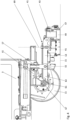
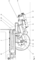
- a dirty liquid receiving device 41 is provided, which is shown in detail in FIGS. 3 to 6 and is designed as a suction foot arrangement in the present exemplary embodiment.
- the dirty liquid receiving device 41 has a base body 43, from which a front suction lip 45 and a rear suction lip 47 extend downwards, the suction lips 45, 47 extending transversely to the longitudinal axis 21 and in the direction of the longitudinal axis 21 are spaced apart from each other.
- the base body 43 and the suction lips 45, 47 delimit a suction volume 49 which is open to the floor surface 15 to be cleaned, but is closed when the lower edges of the suction lips 45, 47 come into contact with the floor surface 15 to be cleaned.
- a connection (not shown) is provided on the base body 43, so that the dirty liquid container 5 is connected to the suction volume 49 with a connecting line (not shown).
- the dirty liquid container 5 is in turn connected to a suction device 51, so that a lower pressure in relation to the ambient pressure can be generated inside the dirty liquid container 5, so that in turn an air flow can be generated from the suction volume 49 into the dirty liquid container 5, through which then on the Dirty liquid located on the floor surface 15 to be cleaned is entrained and conveyed into the dirty liquid container 5.
- the dirty liquid receiving device 41 is held via its base body 43 on a guide rod 53, which in turn is attached to a holder 57 so that it can pivot about a pivot axis 55.
- the holder 57 in turn can be moved by motor essentially parallel to the floor surface 15 to be cleaned and also parallel to the longitudinal axis 21 relative to the machine housing 3 using a linear drive 59 along a guide rail 61, the linear drive 59 being connected to the control unit 39 in a manner not shown .
- the linear drive 59 With the help of the linear drive 59, the Dirty liquid receiving device 41 parallel to the longitudinal axis 21 between a retracted position ( Figures 4 and 5 ) and an extended position ( Figure 3 ).
- the dirty liquid receiving device 41 in the form of the suction cup can be inserted into the in Figure 3 shown extended position, in which the dirty liquid receiving device 41 is further beyond the rear end 25 of the machine housing 3, ie the dirty liquid receiving device 41 is, viewed along the longitudinal axis 21, further away from the rear wheel 11 than in the Figures 4 and 5 shown retracted position, which is achieved by retracting the linear drive 59 so that the holder 57, which holds the guide rod 53, is moved along the guide rail 61 towards the rear wheel 11.
- the dirty liquid receiving device 41 in the form of the suction base can be pivoted about a vertical axis 69, which during operation, i.e. when the dirty liquid receiving device 41 is in the lowered position, runs essentially perpendicular to the floor surface 15 to be cleaned.
- a position, pivoted from a straight position of the suction cup is in Figure 7 to recognize what emerges from the fact that the free ends 71 of the dirty liquid receiving device 41 have different positions along the longitudinal axis 21.
- the width that the dirty liquid receiving device 41 has is obviously larger than the width that the cleaning device 27 has, these widths being determined perpendicular to the longitudinal axis 21.
Landscapes
- Electric Suction Cleaners (AREA)
Applications Claiming Priority (1)
| Application Number | Priority Date | Filing Date | Title |
|---|---|---|---|
| DE102022111608.5A DE102022111608A1 (de) | 2022-05-10 | 2022-05-10 | Bodenreinigungsmaschine und Verfahren zum Betrieb einer Bodenreinigungsmaschine |
Publications (3)
| Publication Number | Publication Date |
|---|---|
| EP4275567A1 true EP4275567A1 (fr) | 2023-11-15 |
| EP4275567B1 EP4275567B1 (fr) | 2025-07-02 |
| EP4275567C0 EP4275567C0 (fr) | 2025-07-02 |
Family
ID=86330612
Family Applications (1)
| Application Number | Title | Priority Date | Filing Date |
|---|---|---|---|
| EP23172052.5A Active EP4275567B1 (fr) | 2022-05-10 | 2023-05-08 | Machine de nettoyage de sol et procédé de fonctionnement d'une machine de nettoyage de sol |
Country Status (5)
| Country | Link |
|---|---|
| US (1) | US20230363604A1 (fr) |
| EP (1) | EP4275567B1 (fr) |
| KR (1) | KR20230157894A (fr) |
| CN (1) | CN117017133A (fr) |
| DE (1) | DE102022111608A1 (fr) |
Families Citing this family (2)
| Publication number | Priority date | Publication date | Assignee | Title |
|---|---|---|---|---|
| WO2026044802A1 (fr) * | 2024-08-30 | 2026-03-05 | 北京石头世纪科技股份有限公司 | Ensemble de nettoyage, dispositif de nettoyage, procédé de commande de dispositif de nettoyage et système de nettoyage |
| JP7854740B1 (ja) * | 2024-12-23 | 2026-05-07 | 株式会社フロアーサポート | 床クリーニング方法 |
Citations (4)
| Publication number | Priority date | Publication date | Assignee | Title |
|---|---|---|---|---|
| JP3267483B2 (ja) * | 1995-09-30 | 2002-03-18 | アマノ株式会社 | 床面洗浄機用スキージの連結装置 |
| EP1913859A1 (fr) * | 2006-10-19 | 2008-04-23 | Hako-Werke GMBH | Machine pour le nettoyage des sols avec un pied de succion pivotant |
| WO2009127836A1 (fr) * | 2008-04-18 | 2009-10-22 | Numatic International Limited | Machine de traitement des sols |
| JP2010075529A (ja) * | 2008-09-26 | 2010-04-08 | Amano Corp | 床面洗浄機用スキージ連結装置 |
Family Cites Families (14)
| Publication number | Priority date | Publication date | Assignee | Title |
|---|---|---|---|---|
| US5623743A (en) * | 1996-06-04 | 1997-04-29 | Clarke Industries, Inc. | Mobile surface scrubber solution recovery system |
| US7640622B2 (en) * | 2004-04-21 | 2010-01-05 | Vankouwenberg Raymond E | Floor surface cleaning and resurfacing equipment |
| EP1887918B1 (fr) * | 2005-05-05 | 2012-11-07 | Tennant Company | Machine a balayer et laver les sols |
| EP2022383B1 (fr) * | 2007-08-02 | 2010-12-15 | Comac S.p.A. | Machine de nettoyage de sol |
| CN202390792U (zh) * | 2011-11-17 | 2012-08-22 | 南通铭德机床有限公司 | 扫地机边刷防撞装置 |
| KR20140070250A (ko) * | 2012-11-30 | 2014-06-10 | 삼성테크윈 주식회사 | 로봇 청소기 |
| EP2954817B1 (fr) * | 2014-06-11 | 2016-10-26 | Hako GmbH | Machine de nettoyage du sol |
| DE102017105921A1 (de) * | 2017-03-20 | 2018-09-20 | Hako Gmbh | Saugfuß für eine Bodenreinigungsmaschine |
| DE102017110775A1 (de) * | 2017-05-17 | 2018-11-22 | Hako Gmbh | Saugfußanordnung für eine Bodenreinigungsmaschine |
| US9981832B1 (en) * | 2017-09-20 | 2018-05-29 | Industries N.R.C. Inc. | Control panel assembly |
| DE102018113691A1 (de) * | 2018-06-08 | 2019-12-12 | Alfred Kärcher SE & Co. KG | Bodenreinigungsmaschine mit Seitenschürzeneinrichtung und Verfahren zum Betreiben einer Bodenreinigungsmaschine |
| WO2021089164A1 (fr) * | 2019-11-07 | 2021-05-14 | Alfred Kärcher SE & Co. KG | Machine de nettoyage de sol et procédé de fonctionnement d'une machine de nettoyage de sol |
| JP7403423B2 (ja) * | 2020-09-29 | 2023-12-22 | 日立グローバルライフソリューションズ株式会社 | ロボット掃除機 |
| CN113425204B (zh) * | 2021-07-12 | 2022-06-07 | 上海高仙自动化科技发展有限公司 | 一种边刷装置及清洁机器人 |
-
2022
- 2022-05-10 DE DE102022111608.5A patent/DE102022111608A1/de active Pending
-
2023
- 2023-05-05 US US18/143,876 patent/US20230363604A1/en active Pending
- 2023-05-08 EP EP23172052.5A patent/EP4275567B1/fr active Active
- 2023-05-09 CN CN202310522749.1A patent/CN117017133A/zh active Pending
- 2023-05-10 KR KR1020230060429A patent/KR20230157894A/ko active Pending
Patent Citations (4)
| Publication number | Priority date | Publication date | Assignee | Title |
|---|---|---|---|---|
| JP3267483B2 (ja) * | 1995-09-30 | 2002-03-18 | アマノ株式会社 | 床面洗浄機用スキージの連結装置 |
| EP1913859A1 (fr) * | 2006-10-19 | 2008-04-23 | Hako-Werke GMBH | Machine pour le nettoyage des sols avec un pied de succion pivotant |
| WO2009127836A1 (fr) * | 2008-04-18 | 2009-10-22 | Numatic International Limited | Machine de traitement des sols |
| JP2010075529A (ja) * | 2008-09-26 | 2010-04-08 | Amano Corp | 床面洗浄機用スキージ連結装置 |
Also Published As
| Publication number | Publication date |
|---|---|
| DE102022111608A1 (de) | 2023-11-16 |
| KR20230157894A (ko) | 2023-11-17 |
| EP4275567B1 (fr) | 2025-07-02 |
| US20230363604A1 (en) | 2023-11-16 |
| CN117017133A (zh) | 2023-11-10 |
| EP4275567C0 (fr) | 2025-07-02 |
Similar Documents
| Publication | Publication Date | Title |
|---|---|---|
| EP0569430B1 (fr) | Machine de traitement de planchers | |
| EP2982285B1 (fr) | Appareil de nettoyage de sol destine au nettoyage sec et humide et procede de fonctionnement d'un appareil de nettoyage de sol automobile | |
| EP4275567B1 (fr) | Machine de nettoyage de sol et procédé de fonctionnement d'une machine de nettoyage de sol | |
| EP3310233B1 (fr) | Buse d'aspiration pour un aspirateur | |
| EP3409165B1 (fr) | Dispositif de support sur un robot de nettoyage | |
| DE102007054500A1 (de) | Verfahrbares Haushalts-Bodenreinigungsgerät sowie Befeuchtungseinrichtung für eine Wischwalze | |
| DE102014116589A1 (de) | Saugdüse mit einer Stützrolle | |
| DE4100333A1 (de) | Mechanismus zur hoeheneinstellung von bodenreinigungsgeraeten | |
| EP3451886B1 (fr) | Système de traitement des sols | |
| DE2319618A1 (de) | Flurfoerderzeug mit deichsel fuer automatischen und/oder handbetrieb | |
| WO2016083213A1 (fr) | Installation de lavage à portique et procédé de nettoyage d'un véhicule automobile | |
| EP2570310A1 (fr) | Procédé de lavage d'un véhicule et installation de lavage de véhicule destinée à l'exécution du procédé | |
| EP4295739A1 (fr) | Procédé de fonctionnement d'une machine de nettoyage de sol | |
| EP3106567B1 (fr) | Machine de nettoyage du sol dotée d'un dispositif d'absorption de liquide | |
| EP1219225B1 (fr) | Dispositif d'humidification des serpillières | |
| EP4275570B1 (fr) | Pont à rouleaux pour une machine de nettoyage de sol et machine de nettoyage de sol dotée d'un pont à rouleaux | |
| DE102017118487A1 (de) | Saugdüse für ein ein Sauggebläse aufweisendes Reinigungsgerät | |
| EP1913859B1 (fr) | Machine pour le nettoyage des sols avec un pied de succion pivotant | |
| DE102013204398A1 (de) | Bodenreinigungsmaschine mit einer Flüssigkeitsversorgungseinrichtung für die Reinigungseinheit | |
| EP1838198B1 (fr) | Dispositif de type serpilliere humide a support plat | |
| DE9115713U1 (de) | Scheuersaugmaschine | |
| EP4195988B1 (fr) | Appareil de traitement de plancher | |
| WO1993010911A1 (fr) | Dispositif de conditionnement exterieur de vehicules a moteur | |
| EP3451887B1 (fr) | Système de traîtement des sols | |
| DE4230196C1 (de) | Bodenbearbeitungsmaschine |
Legal Events
| Date | Code | Title | Description |
|---|---|---|---|
| PUAI | Public reference made under article 153(3) epc to a published international application that has entered the european phase |
Free format text: ORIGINAL CODE: 0009012 |
|
| STAA | Information on the status of an ep patent application or granted ep patent |
Free format text: STATUS: THE APPLICATION HAS BEEN PUBLISHED |
|
| AK | Designated contracting states |
Kind code of ref document: A1 Designated state(s): AL AT BE BG CH CY CZ DE DK EE ES FI FR GB GR HR HU IE IS IT LI LT LU LV MC ME MK MT NL NO PL PT RO RS SE SI SK SM TR |
|
| STAA | Information on the status of an ep patent application or granted ep patent |
Free format text: STATUS: REQUEST FOR EXAMINATION WAS MADE |
|
| REG | Reference to a national code |
Ref country code: HK Ref legal event code: DE Ref document number: 40103734 Country of ref document: HK |
|
| 17P | Request for examination filed |
Effective date: 20240515 |
|
| RBV | Designated contracting states (corrected) |
Designated state(s): AL AT BE BG CH CY CZ DE DK EE ES FI FR GB GR HR HU IE IS IT LI LT LU LV MC ME MK MT NL NO PL PT RO RS SE SI SK SM TR |
|
| GRAP | Despatch of communication of intention to grant a patent |
Free format text: ORIGINAL CODE: EPIDOSNIGR1 |
|
| STAA | Information on the status of an ep patent application or granted ep patent |
Free format text: STATUS: GRANT OF PATENT IS INTENDED |
|
| INTG | Intention to grant announced |
Effective date: 20241209 |
|
| GRAS | Grant fee paid |
Free format text: ORIGINAL CODE: EPIDOSNIGR3 |
|
| GRAA | (expected) grant |
Free format text: ORIGINAL CODE: 0009210 |
|
| STAA | Information on the status of an ep patent application or granted ep patent |
Free format text: STATUS: THE PATENT HAS BEEN GRANTED |
|
| AK | Designated contracting states |
Kind code of ref document: B1 Designated state(s): AL AT BE BG CH CY CZ DE DK EE ES FI FR GB GR HR HU IE IS IT LI LT LU LV MC ME MK MT NL NO PL PT RO RS SE SI SK SM TR |
|
| REG | Reference to a national code |
Ref country code: GB Ref legal event code: FG4D Free format text: NOT ENGLISH |
|
| REG | Reference to a national code |
Ref country code: CH Ref legal event code: EP |
|
| REG | Reference to a national code |
Ref country code: DE Ref legal event code: R096 Ref document number: 502023001253 Country of ref document: DE |
|
| REG | Reference to a national code |
Ref country code: IE Ref legal event code: FG4D Free format text: LANGUAGE OF EP DOCUMENT: GERMAN |
|
| U01 | Request for unitary effect filed |
Effective date: 20250801 |
|
| U07 | Unitary effect registered |
Designated state(s): AT BE BG DE DK EE FI FR IT LT LU LV MT NL PT RO SE SI Effective date: 20250812 |
|
| PG25 | Lapsed in a contracting state [announced via postgrant information from national office to epo] |
Ref country code: IS Free format text: LAPSE BECAUSE OF FAILURE TO SUBMIT A TRANSLATION OF THE DESCRIPTION OR TO PAY THE FEE WITHIN THE PRESCRIBED TIME-LIMIT Effective date: 20251102 |
|
| PG25 | Lapsed in a contracting state [announced via postgrant information from national office to epo] |
Ref country code: NO Free format text: LAPSE BECAUSE OF FAILURE TO SUBMIT A TRANSLATION OF THE DESCRIPTION OR TO PAY THE FEE WITHIN THE PRESCRIBED TIME-LIMIT Effective date: 20251002 |
|
| PG25 | Lapsed in a contracting state [announced via postgrant information from national office to epo] |
Ref country code: HR Free format text: LAPSE BECAUSE OF FAILURE TO SUBMIT A TRANSLATION OF THE DESCRIPTION OR TO PAY THE FEE WITHIN THE PRESCRIBED TIME-LIMIT Effective date: 20250702 |
|
| PG25 | Lapsed in a contracting state [announced via postgrant information from national office to epo] |
Ref country code: GR Free format text: LAPSE BECAUSE OF FAILURE TO SUBMIT A TRANSLATION OF THE DESCRIPTION OR TO PAY THE FEE WITHIN THE PRESCRIBED TIME-LIMIT Effective date: 20251003 |
|
| PG25 | Lapsed in a contracting state [announced via postgrant information from national office to epo] |
Ref country code: CZ Free format text: LAPSE BECAUSE OF FAILURE TO SUBMIT A TRANSLATION OF THE DESCRIPTION OR TO PAY THE FEE WITHIN THE PRESCRIBED TIME-LIMIT Effective date: 20250702 |
|
| PG25 | Lapsed in a contracting state [announced via postgrant information from national office to epo] |
Ref country code: PL Free format text: LAPSE BECAUSE OF FAILURE TO SUBMIT A TRANSLATION OF THE DESCRIPTION OR TO PAY THE FEE WITHIN THE PRESCRIBED TIME-LIMIT Effective date: 20250702 |
|
| PG25 | Lapsed in a contracting state [announced via postgrant information from national office to epo] |
Ref country code: RS Free format text: LAPSE BECAUSE OF FAILURE TO SUBMIT A TRANSLATION OF THE DESCRIPTION OR TO PAY THE FEE WITHIN THE PRESCRIBED TIME-LIMIT Effective date: 20251002 |
|
| PG25 | Lapsed in a contracting state [announced via postgrant information from national office to epo] |
Ref country code: ES Free format text: LAPSE BECAUSE OF FAILURE TO SUBMIT A TRANSLATION OF THE DESCRIPTION OR TO PAY THE FEE WITHIN THE PRESCRIBED TIME-LIMIT Effective date: 20250702 |
|
| PG25 | Lapsed in a contracting state [announced via postgrant information from national office to epo] |
Ref country code: SM Free format text: LAPSE BECAUSE OF FAILURE TO SUBMIT A TRANSLATION OF THE DESCRIPTION OR TO PAY THE FEE WITHIN THE PRESCRIBED TIME-LIMIT Effective date: 20250702 |
|
| PG25 | Lapsed in a contracting state [announced via postgrant information from national office to epo] |
Ref country code: SK Free format text: LAPSE BECAUSE OF FAILURE TO SUBMIT A TRANSLATION OF THE DESCRIPTION OR TO PAY THE FEE WITHIN THE PRESCRIBED TIME-LIMIT Effective date: 20250702 |
|
| PLBE | No opposition filed within time limit |
Free format text: ORIGINAL CODE: 0009261 |
|
| STAA | Information on the status of an ep patent application or granted ep patent |
Free format text: STATUS: NO OPPOSITION FILED WITHIN TIME LIMIT |