EP4275931A1 - Système de chauffage d'une machine de construction électrique - Google Patents
Système de chauffage d'une machine de construction électrique Download PDFInfo
- Publication number
- EP4275931A1 EP4275931A1 EP22739797.3A EP22739797A EP4275931A1 EP 4275931 A1 EP4275931 A1 EP 4275931A1 EP 22739797 A EP22739797 A EP 22739797A EP 4275931 A1 EP4275931 A1 EP 4275931A1
- Authority
- EP
- European Patent Office
- Prior art keywords
- working fluid
- temperature
- construction machine
- heater system
- heater
- Prior art date
- Legal status (The legal status is an assumption and is not a legal conclusion. Google has not performed a legal analysis and makes no representation as to the accuracy of the status listed.)
- Granted
Links
Images



Classifications
-
- E—FIXED CONSTRUCTIONS
- E02—HYDRAULIC ENGINEERING; FOUNDATIONS; SOIL SHIFTING
- E02F—DREDGING; SOIL-SHIFTING
- E02F9/00—Component parts of dredgers or soil-shifting machines, not restricted to one of the kinds covered by groups E02F3/00 - E02F7/00
- E02F9/20—Drives; Control devices
- E02F9/2058—Electric or electro-mechanical or mechanical control devices of vehicle sub-units
- E02F9/2062—Control of propulsion units
- E02F9/207—Control of propulsion units of the type electric propulsion units, e.g. electric motors or generators
-
- E—FIXED CONSTRUCTIONS
- E02—HYDRAULIC ENGINEERING; FOUNDATIONS; SOIL SHIFTING
- E02F—DREDGING; SOIL-SHIFTING
- E02F9/00—Component parts of dredgers or soil-shifting machines, not restricted to one of the kinds covered by groups E02F3/00 - E02F7/00
- E02F9/08—Superstructures; Supports for superstructures
-
- B—PERFORMING OPERATIONS; TRANSPORTING
- B60—VEHICLES IN GENERAL
- B60H—ARRANGEMENTS OF HEATING, COOLING, VENTILATING OR OTHER AIR-TREATING DEVICES SPECIALLY ADAPTED FOR PASSENGER OR GOODS SPACES OF VEHICLES
- B60H1/00—Heating, cooling or ventilating devices
- B60H1/00357—Air-conditioning arrangements specially adapted for particular vehicles
- B60H1/00378—Air-conditioning arrangements specially adapted for particular vehicles for tractor or load vehicle cabins
-
- B—PERFORMING OPERATIONS; TRANSPORTING
- B60—VEHICLES IN GENERAL
- B60H—ARRANGEMENTS OF HEATING, COOLING, VENTILATING OR OTHER AIR-TREATING DEVICES SPECIALLY ADAPTED FOR PASSENGER OR GOODS SPACES OF VEHICLES
- B60H1/00—Heating, cooling or ventilating devices
- B60H1/02—Heating, cooling or ventilating devices the heat being derived from the propulsion plant
- B60H1/14—Heating, cooling or ventilating devices the heat being derived from the propulsion plant other than from cooling liquid of the plant
-
- B—PERFORMING OPERATIONS; TRANSPORTING
- B60—VEHICLES IN GENERAL
- B60H—ARRANGEMENTS OF HEATING, COOLING, VENTILATING OR OTHER AIR-TREATING DEVICES SPECIALLY ADAPTED FOR PASSENGER OR GOODS SPACES OF VEHICLES
- B60H1/00—Heating, cooling or ventilating devices
- B60H1/02—Heating, cooling or ventilating devices the heat being derived from the propulsion plant
- B60H1/14—Heating, cooling or ventilating devices the heat being derived from the propulsion plant other than from cooling liquid of the plant
- B60H1/143—Heating, cooling or ventilating devices the heat being derived from the propulsion plant other than from cooling liquid of the plant the heat being derived from cooling an electric component, e.g. electric motors, electric circuits, fuel cells or batteries
-
- E—FIXED CONSTRUCTIONS
- E02—HYDRAULIC ENGINEERING; FOUNDATIONS; SOIL SHIFTING
- E02F—DREDGING; SOIL-SHIFTING
- E02F9/00—Component parts of dredgers or soil-shifting machines, not restricted to one of the kinds covered by groups E02F3/00 - E02F7/00
- E02F9/20—Drives; Control devices
- E02F9/22—Hydraulic or pneumatic drives
-
- E—FIXED CONSTRUCTIONS
- E02—HYDRAULIC ENGINEERING; FOUNDATIONS; SOIL SHIFTING
- E02F—DREDGING; SOIL-SHIFTING
- E02F9/00—Component parts of dredgers or soil-shifting machines, not restricted to one of the kinds covered by groups E02F3/00 - E02F7/00
- E02F9/20—Drives; Control devices
- E02F9/22—Hydraulic or pneumatic drives
- E02F9/226—Safety arrangements, e.g. hydraulic driven fans, preventing cavitation, leakage, overheating
-
- B—PERFORMING OPERATIONS; TRANSPORTING
- B60—VEHICLES IN GENERAL
- B60H—ARRANGEMENTS OF HEATING, COOLING, VENTILATING OR OTHER AIR-TREATING DEVICES SPECIALLY ADAPTED FOR PASSENGER OR GOODS SPACES OF VEHICLES
- B60H1/00—Heating, cooling or ventilating devices
- B60H1/22—Heating, cooling or ventilating devices the heat source being other than the propulsion plant
-
- E—FIXED CONSTRUCTIONS
- E02—HYDRAULIC ENGINEERING; FOUNDATIONS; SOIL SHIFTING
- E02F—DREDGING; SOIL-SHIFTING
- E02F9/00—Component parts of dredgers or soil-shifting machines, not restricted to one of the kinds covered by groups E02F3/00 - E02F7/00
- E02F9/16—Cabins, platforms, or the like, for drivers
- E02F9/163—Structures to protect drivers, e.g. cabins, doors for cabins; Falling object protection structure [FOPS]; Roll over protection structure [ROPS]
Definitions
- the present invention relates to a heater system for an electric construction machine.
- a working device such as a bucket of an excavator or a traveling device is driven by an working fluid delivered from a hydraulic pump.
- a hydraulic pump is driven by an internal combustion engine.
- an excavator driven by an engine emits not only exhausts but also loud noise, so it is not suitable for work at construction sites such as hospitals or schools that are sensitive to smoke or noise.
- an electric excavator which drives a hydraulic pump using an electric motor connected to a battery has recently been developed.
- Engine-driven excavators use engine cooling water to heat the driver's seat. More specifically, in the case of an engine-driven excavator, cooling water for cooling the engine cools the engine while flowing along a flow path formed in the engine by a water pump, and the cooling water heated by the engine is circulated to a radiator to be cooled. Part of the cooling water heated by the engine is diverted to a heat exchanger and used as a heat source for heating the driver's seat.
- the present invention is directed to a heater system for an electric construction machine capable of heating a cabin.
- the heater system in a heater system of an electric construction machine including a hydraulic pump driven by an electric motor and a main control valve configured to supply a working fluid discharged from the hydraulic pump to at least one actuator, the heater system includes: a heater core which is disposed downstream of the actuator and through which the working fluid passes, wherein a heated air is supplied to a cabin through the heater core using a heat of the working fluid.
- the heater system of an electric construction machine may further include: a switching valve configured to selectively supply the working fluid to the heater core.
- the heater system of an electric construction machine may further include: an oil cooler configured to control a temperature of the working fluid.
- the heater system of an electric construction machine may further include: an oil cooler disposed upstream of the heater core and configured to control a temperature of the working fluid.
- the oil cooler may be disposed between the switching valve and a working fluid tank or between the switching valve and the main control valve.
- a flow path of the working fluid supplied through the switching valve may be branched into each of the heater core, the oil cooler and a working fluid tank.
- the switching valve may be switched so that the working fluid is supplied to the working fluid tank.
- the switching valve may be switched so that the working fluid is supplied to the heater core or the working fluid tank.
- the switching valve may be switched so that the working fluid is supplied to the heater core, the oil cooler or the working fluid tank.
- the heater system of an electric construction machine may further include: a fan member configured to control the temperature of the working fluid passing through the oil cooler through control of a rotational speed.
- the heater system of an electric construction machine may further include: an auxiliary heating device configured to supply the heated air to the cabin.
- the switching valve may be configured to supply the working fluid to the heater core according to a worker's ON signal.
- operation of the fan member may be stopped when the temperature of the working fluid is equal to or less than a preset temperature.
- the fan member may be operated only when the temperature of the working fluid is equal to or higher than a preset temperature.
- a heater system for an electric construction machine may be applied without a significant change to the conventional hydraulic system or air conditioning system, thereby reducing cost or time in the manufacturing process.
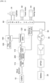
- FIG. 1 is a view conceptually illustrating a supply path of a working fluid (e.g., hydraulic oil) when a heater system of an electric construction machine according to an embodiment of the present invention is in an OFF state
- FIG. 2 is a view conceptually illustrating a supply path of a working fluid when a heater system of an electric construction machine according to an embodiment of the present invention is in an ON state
- FIG. 3 is a view conceptually illustrating a supply path of a working fluid when a heater system of an electric construction machine is in an OFF state in another embodiment of the present invention
- FIG. 4 is a view conceptually illustrating a supply path of a working fluid when a heater system of an electric construction machine is in an ON state in another embodiment of the present invention
- FIG. 1 is a view conceptually illustrating a supply path of a working fluid (e.g., hydraulic oil) when a heater system of an electric construction machine according to an embodiment of the present invention is in an OFF state
- FIG. 2 is a view conceptually
- FIG. 5 is a view conceptually illustrating a supply path of a working fluid when a temperature of a working fluid in a heater system of an electric construction machine according to an exemplary embodiment of the present invention is equal to or less than a preset first temperature
- FIG. 6 is a view conceptually illustrating a supply path of a working fluid when a temperature of a working fluid is higher than a preset first temperature in a heater system of an electric construction machine according to an exemplary embodiment of the present invention
- FIG. 7 is a view conceptually illustrating a supply path of a working fluid when a temperature of a working fluid is higher than a preset second temperature in a heater system of an electric construction machine according to an exemplary embodiment of the present invention
- FIG. 8 is a graph illustrating a rotational speed control state of a fan member 155 according to a temperature of a working fluid flowing into an oil cooler 150 in a heater system of an electric construction machine according to various embodiments of the present invention.
- a heater system of an electric construction machine relates to a heater system applied to an electric construction machine driven by an electric motor 30.
- an electric construction machine to which a heater system of the present invention is applied replaces an internal combustion engine such as an engine and has a structure in which a hydraulic pump 50 is driven through an electric motor 30 using a battery 20.
- a working fluid for operating an actuator 90 such as a work apparatus is discharged from the pump.
- the working fluid discharged from the pump may be supplied to the actuator 90 for operating a cylinder 91 such as a boom, arm, bucket, and the like, a travel motor 92, or a swing motor 93 through a main control valve (MCV) 80.
- MCV main control valve
- a temperature of the working fluid increases in the process of operating the actuator 90, and the present invention proposes a method of using the heat of the working fluid used when operating the construction machine as a heat source.
- the heater system of the electric construction machine may include a heater core 110, a switching valve 120, and an oil cooler 150.
- a fan member 155 of the oil cooler 150 and an auxiliary heating device 200 may be further included.
- a control switch capable of controlling on/off of the heater system may be disposed inside a cabin 10, and operation of the heater system may be determined by an worker manipulating the control switch.
- operation of the heater system may be determined by an worker manipulating the control switch.
- the heater core may be disposed downstream of the main control valve 80 and may form a flow path through which the working fluid may flow therein.
- the heater core 110 may be formed in various structures, and is not limited to its shape.
- a working fluid whose temperature has increased may flow into the heater core 110.
- the temperature of the heater core 110 rises due to the temperature of the working fluid, and a waste heat of the working fluid may be recovered by using the heater core 110.
- the heat of the working fluid may be recovered by passing the working fluid through the heater core 110 so that the heated air may be supplied to the inside of the cabin 10.
- a heater fan 115 for generating a flow of air toward the inside of the cabin 10 may be disposed on one side of the heater core 110.
- the working fluid whose heat is recovered through the heater core 110 may be supplied to the pump again through the working fluid tank 60 in a state in which the temperature is lowered again.
- a switching valve 120 may be disposed upstream of the heater core 110.
- the switching valve 120 may be switched by an operation signal of the control switch.
- a supply line of the working fluid passing through the actuator 90 may be controlled through the switching valve 120.
- the switching valve 120 is switched according to whether the control switch of the heater system is operated by the worker, the working fluid passing through the actuator 90 may be selectively supplied to the working fluid tank 60 or the heater core 110.
- the switching valve 120 when a worker turns on the heater system, the switching valve 120 may be switched to supply the working fluid to the heater core 110 according to a corresponding signal. Also, when the worker turns off the heater system, the switching valve 120 may be switched so that the working fluid does not flow into the heater core 110 and is returned to the working fluid tank 60.
- the switching valve 120 and the heater core 110 may be disposed downstream of the oil cooler 150. In this case, the temperature of the working fluid flowing into the heater core 110 through the switching valve 120 may be properly adjusted by the oil cooler 150.
- the switching valve 120 and the heater core 110 may be disposed upstream of the oil cooler 150.
- the working fluid may be recovered to the working fluid tank 60 in a cooled state by the oil cooler 150.
- the heater system of the electric construction machine of the present invention may include the oil cooler 150.
- the oil cooler 150 may be disposed on the working fluid flow path to control the temperature of the working fluid whose temperature has increased while passing through the actuator 90.
- At least one temperature sensor capable of sensing the temperature of the working fluid may be disposed in the oil cooler 150.
- the fan member 155 installed on one side of the oil cooler 150 is operated to cool the working fluid inside the oil cooler 150.
- the temperature of the working fluid may be controlled by controlling a rotational speed of the fan member 155.
- the oil cooler 150 is disposed upstream of the switching valve 120 and the heater core 110 to adjust the temperature of working fluid flowing into the heater core 110.
- the working fluid whose temperature has risen in the process of passing through the actuator 90 may be supplied to the heater core 110 or the working fluid tank 60 while the temperature is constantly controlled through the oil cooler 150.
- the control switch of the heater system When the control switch of the heater system is in the OFF state, the working fluid may be returned to the working fluid tank 60 through the switching valve 120 and supplied to the hydraulic pump 50 again, and in one embodiment, the oil cooler 150 may control the working fluid temperature to a preset temperature.
- the preset maximum temperature may be 80 degrees as illustrated in (a) of FIG. 8 , and in such a case, the fan member 155 of the oil cooler 150 may operate from approximately 30 degrees to control the temperature of the working oil to 80 degrees while constantly increasing the rotational speed.
- the working fluid when the control switch of the heater system is in an ON state, the working fluid may be supplied to the heater core 110 through the switching valve 120.
- the oil cooler 150 may control the temperature of the working fluid flowing into the heater core 110 to reach a preset maximum temperature.
- the oil cooler 150 may operate the fan member 155 only when the temperature of the working fluid is equal to or higher than a preset minimum temperature and may stop the operation of the fan member 155 when the working fluid temperature is lower than the preset minimum temperature. This is because air sufficiently heated through the heater core 110 may not be provided to the cabin 10 when the temperature of the working fluid is less than the preset minimum temperature.
- hot air may be supplied to the cabin 10 through an auxiliary heating device 200 such as a positive temperature coefficient (PTC) heater or a heat pump. Thereafter, when the temperature of the working fluid rises to or above the preset minimum temperature, the operation of the auxiliary heating device 200 is stopped, and the heated air may be supplied to the cabin 10 by using the heat of the working fluid recovered through the heater core 110.
- PTC positive temperature coefficient
- the preset maximum temperature may be 80 degrees as in the case where the control switch is in an OFF state, but embodiments are not limited thereto, and the appropriate temperature may be changed according to the intensity (temperature) of the heater requested by the driver.
- an operating start temperature of the fan member 155 when the control switch is in an ON state, an operating start temperature of the fan member 155 may be set higher than the case when the control switch is in an OFF state.
- the operating start temperature of the fan member 155 when the control switch is in an ON state may be set to a second temperature, for example, may be exemplarily set to 50 degrees as illustrated in (b) of FIG. 8 , which is higher than a first temperature that is the operating start temperature of the fan member 155 when the control switch is in an OFF state.
- the fan member 155 may operate at a temperature of about 50 degrees and control the temperature of the working fluid to be 80 degrees while constantly increasing the rotational speed.
- the heated air may be generated through the heater core 110 using the heat of the working fluid, but since it is difficult to supply the heated air to the cabin 10 in a state where the temperature of the working fluid has not sufficiently risen after starting the construction machine, the auxiliary heating device 200 may be further provided.
- the auxiliary heating device 200 may include a PTC heater or a heat pump, but embodiments are not limited thereto, and it is obvious that any known heating device other than a heating device using waste heat of a working fluid may be used.
- the switching valve 120 when the control switch of the heater system is operated to an ON state, the switching valve 120 is switched and the working fluid passing through the oil cooler 150 may flow into the heater core 110.
- the operation of the fan member 155 of the oil cooler 150 may be stopped.
- the heated air since the heater core 110 alone may not provide sufficiently heated air, the heated air may be supplied to the cabin 10 through the auxiliary heating device 200.
- the operation of the auxiliary heating device 200 is stopped and the heated air may be provided through the heater core 110.
- the operation of the fan member 155 of the oil cooler 150 starts, and the maximum temperature of the working fluid may be controlled to be 80 degrees while constantly increasing the rotational speed as illustrated in (b) of FIG. 8 .
- the oil cooler 150 may be disposed downstream of the switching valve 120 or the heater core 110 as illustrated in FIGS. 3 and 4 .
- the oil cooler 150 may be disposed downstream of the switching valve 120, that is, between the switching valve 120 and the working fluid tank 60.
- the fan member 155 of the oil cooler 150 may be controlled as in the case where the control switch of the heater system is off.
- the temperature of the hot working fluid may be lowered while passing through the oil cooler 150 via the switching valve 120 and the working fluid may return to the working fluid tank 60.
- FIG. 4 when the driver turns on the control switch of the heater system, the switching valve 120 is switched and the hot working fluid is introduced into the heater core 110 without passing through the oil cooler 150, and heating of the cabin may be performed by the heat of hydraulic oil.
- the switching valve 120 may be a four-way switching valve.
- the flow path of the working fluid supplied through the switching valve 120 may be configured to branch to each of the heater core 110, the oil cooler 150 and the working fluid tank 60.
- the switching valve 120 may be switched so that the working fluid is supplied to the working fluid tank 60. Due to switching of the switching valve 120, the flow path communicating from the switching valve 120 to the heater core 110 and the oil cooler 150 may be closed, such that the working fluid may be directly recovered to the working fluid tank 60 without passing through the heater core 110 or the oil cooler 150.
- the preset first temperature may be a temperature low enough to make it difficult to use the heater core 110, and may be set to, for example, 40 degrees, but embodiments are not limited thereto. That is, in FIG. 5 , since the working fluid that is not sufficiently hot may circulate quickly along the hydraulic system of the construction machine through the hydraulic pump 50, the temperature may rise quickly.
- the switching valve 120 when the temperature of the working fluid supplied from the main control valve 80 is higher than the preset first temperature, the switching valve 120 maybe switched such that the working fluid may be supplied to the heater core 110 or the working fluid tank 60.
- the preset first temperature may be a temperature low enough to make it difficult to use the heater core 110, and may be set to, for example, 40 degrees, but embodiments are not limited thereto.
- the working fluid since the temperature of the working fluid is appropriately high enough to be used in the heater core, the working fluid may be supplied to the heater core 110 according to the control switch operation of the heater system by the worker and may be used as a heat source of the heater. In this case, since the temperature of the working fluid is not hot enough to require cooling, the flow path communicating from the switching valve 120 to the oil cooler 150 may be closed.
- the switching valve 120 may be switched such that the working fluid may be supplied to any one of the heater core 110, the oil cooler 150, and the working fluid tank 60.
- the preset second temperature may be a temperature at which the temperature of the working fluid becomes hot enough to require cooling using the oil cooler 150 according to the operation of the construction machine, and may be set to, for example, 80 degrees, but embodiments are not limited thereto.
- the hot working fluid that has passed through the switching valve 120 may be supplied to the heater core 110 according to the control switch operation of the heater system by the worker and may be used as a heat source for the heater or may be supplied to the oil cooler 150 for cooling.
- control of the rotational speed of the fan member 155 of the oil cooler 150 is the same as in the above-described embodiment.
- the working fluid may be directly recovered to the working fluid tank 60 without being supplied to the heater core 110 or the oil cooler 150.
- the working fluid whose heat has been recovered through the heater core 110 or the working fluid whose temperature is controlled to maintain the proper maximum temperature by the oil cooler 150 may be continuously circulated by being supplied again to the hydraulic pump 50 via the working fluid tank 60.
- the heater system proposed in the present invention may be applied to an air mixed type air conditioner, and in this case, the temperature of the air supplied to the cabin 10 may be adjusted by mixing the heated air generated by recovering heat from the working fluid through the heater core 110 and the cooled air generated from an air conditioner.
- the temperature of the air supplied to the cabin 10 may be adjusted by controlling a flow rate of the working fluid flowing into the heater core 110.
- the heater system of the electric construction machine may be applied to the conventional hydraulic system or air conditioning system without a significant change, thereby reducing cost or time in the manufacturing process.
- the working fluid of the conventional hydraulic system in the electric construction machine as a heat source, there is no need to install a separate heating device, which has the effect of reducing manufacturing costs.
- the auxiliary heating device 200 even when the auxiliary heating device 200 is operated, since it is limitedly operated according to the temperature of the working fluid, the use time thereof may be reduced, thereby reducing the electrical energy of the battery 20.
Landscapes
- Engineering & Computer Science (AREA)
- Mining & Mineral Resources (AREA)
- Civil Engineering (AREA)
- General Engineering & Computer Science (AREA)
- Structural Engineering (AREA)
- Physics & Mathematics (AREA)
- Thermal Sciences (AREA)
- Mechanical Engineering (AREA)
- Chemical & Material Sciences (AREA)
- Combustion & Propulsion (AREA)
- Air-Conditioning For Vehicles (AREA)
- Component Parts Of Construction Machinery (AREA)
Applications Claiming Priority (2)
| Application Number | Priority Date | Filing Date | Title |
|---|---|---|---|
| KR20210006309 | 2021-01-15 | ||
| PCT/KR2022/000782 WO2022154605A1 (fr) | 2021-01-15 | 2022-01-14 | Système de chauffage d'une machine de construction électrique |
Publications (3)
| Publication Number | Publication Date |
|---|---|
| EP4275931A1 true EP4275931A1 (fr) | 2023-11-15 |
| EP4275931A4 EP4275931A4 (fr) | 2024-08-07 |
| EP4275931B1 EP4275931B1 (fr) | 2025-08-13 |
Family
ID=82448587
Family Applications (1)
| Application Number | Title | Priority Date | Filing Date |
|---|---|---|---|
| EP22739797.3A Active EP4275931B1 (fr) | 2021-01-15 | 2022-01-14 | Système de chauffage d'une machine de construction électrique |
Country Status (3)
| Country | Link |
|---|---|
| EP (1) | EP4275931B1 (fr) |
| KR (1) | KR102872526B1 (fr) |
| WO (1) | WO2022154605A1 (fr) |
Cited By (1)
| Publication number | Priority date | Publication date | Assignee | Title |
|---|---|---|---|---|
| EP4644618A4 (fr) * | 2022-12-27 | 2026-04-29 | Hd Hyundai Infracore Co Ltd | Engin de chantier et dispositif de gestion de chaleur installé à l'intérieur de celui-ci |
Families Citing this family (2)
| Publication number | Priority date | Publication date | Assignee | Title |
|---|---|---|---|---|
| CN117002217A (zh) * | 2023-06-29 | 2023-11-07 | 中联重科土方机械有限公司 | 用于热管理系统的控制方法、电动挖掘机及控制器 |
| FI20236160A1 (en) * | 2023-10-19 | 2025-04-20 | Normet Oy | Thermal management system for an underground machine |
Family Cites Families (9)
| Publication number | Priority date | Publication date | Assignee | Title |
|---|---|---|---|---|
| IT1168237B (it) * | 1982-11-20 | 1987-05-20 | Orenstein & Koppel Ag | Sistema per la utilizzazione del calore disperso di macchine operatrici ad azionamento idraulico |
| US5355939A (en) * | 1991-11-18 | 1994-10-18 | Sanden Corporation | Hydraulically driven vehicular air conditioning system with valve cleaning feature |
| JP2002180501A (ja) * | 2000-12-14 | 2002-06-26 | Hitachi Constr Mach Co Ltd | 建設機械の運転室および該運転室に設けられるコンソール |
| KR101389615B1 (ko) * | 2007-08-02 | 2014-05-07 | 두산인프라코어 주식회사 | 전기 굴삭기의 히팅 장치 |
| JP2011020640A (ja) * | 2009-07-17 | 2011-02-03 | Hitachi Constr Mach Co Ltd | 電動式ショベルの作動油回路 |
| JP2013082260A (ja) * | 2011-10-06 | 2013-05-09 | Hitachi Constr Mach Co Ltd | 作業機械用暖房装置 |
| JP6795987B2 (ja) * | 2017-01-18 | 2020-12-02 | 日野自動車株式会社 | 電動車両用冷却装置 |
| KR102017587B1 (ko) * | 2018-12-14 | 2019-09-05 | 김찬영 | 난방 기능을 제공하는 유압 시스템 및 그를 포함하는 카고 크레인 |
| JP7843142B2 (ja) * | 2022-01-12 | 2026-04-09 | 興和株式会社 | 光学設計方法 |
-
2022
- 2022-01-14 KR KR1020237023841A patent/KR102872526B1/ko active Active
- 2022-01-14 WO PCT/KR2022/000782 patent/WO2022154605A1/fr not_active Ceased
- 2022-01-14 EP EP22739797.3A patent/EP4275931B1/fr active Active
Cited By (1)
| Publication number | Priority date | Publication date | Assignee | Title |
|---|---|---|---|---|
| EP4644618A4 (fr) * | 2022-12-27 | 2026-04-29 | Hd Hyundai Infracore Co Ltd | Engin de chantier et dispositif de gestion de chaleur installé à l'intérieur de celui-ci |
Also Published As
| Publication number | Publication date |
|---|---|
| WO2022154605A1 (fr) | 2022-07-21 |
| EP4275931B1 (fr) | 2025-08-13 |
| EP4275931A4 (fr) | 2024-08-07 |
| KR20230120658A (ko) | 2023-08-17 |
| KR102872526B1 (ko) | 2025-10-17 |
Similar Documents
| Publication | Publication Date | Title |
|---|---|---|
| EP4275931B1 (fr) | Système de chauffage d'une machine de construction électrique | |
| US10450723B2 (en) | Hybrid construction machinery | |
| CN205818861U (zh) | 电动车辆热管理系统和使用该系统的电动车辆 | |
| US6899162B2 (en) | Device for cooling and heating a motor vehicle | |
| US7614368B2 (en) | Automated no-idle heating and engine pre-heat using engine coolant | |
| JP2000054838A (ja) | ハイブリッド車の駆動ユニットを冷却し且つハイブリッド車の内部空間を加熱するためのシステム | |
| JP6287625B2 (ja) | 内燃機関の冷却システム | |
| CN107662696B (zh) | 用于操作船舶的冷却系统的方法 | |
| KR20190120936A (ko) | 차량의 열관리 시스템 | |
| KR101703667B1 (ko) | 차량용 공조장치 | |
| JP2013086717A (ja) | ハイブリッド車両用冷却システム | |
| JP2020117048A (ja) | 温度調整装置 | |
| US11085357B2 (en) | Method and device for ventilating a heat management system of an internal combustion engine | |
| US20040187505A1 (en) | Integrated cooling system | |
| JP2012239344A (ja) | 電動車両の暖機装置 | |
| CN116568537A (zh) | 用于车辆的热管理系统和用于运行热管理系统的方法 | |
| US20060081355A1 (en) | System and method for regulating the heat management of a vehicle | |
| KR101389615B1 (ko) | 전기 굴삭기의 히팅 장치 | |
| JP2012154222A (ja) | 内燃機関の冷却装置 | |
| CN112572093B (zh) | 热管理系统和工程机械 | |
| CN119032209A (zh) | 电动式工程机械 | |
| JP3478140B2 (ja) | 暖房装置 | |
| JP2010169010A (ja) | 内燃機関の冷却装置 | |
| JP2017096167A (ja) | エンジン冷却装置 | |
| WO2017199866A1 (fr) | Dispositif de refroidissement de véhicule |
Legal Events
| Date | Code | Title | Description |
|---|---|---|---|
| STAA | Information on the status of an ep patent application or granted ep patent |
Free format text: STATUS: THE INTERNATIONAL PUBLICATION HAS BEEN MADE |
|
| PUAI | Public reference made under article 153(3) epc to a published international application that has entered the european phase |
Free format text: ORIGINAL CODE: 0009012 |
|
| STAA | Information on the status of an ep patent application or granted ep patent |
Free format text: STATUS: REQUEST FOR EXAMINATION WAS MADE |
|
| 17P | Request for examination filed |
Effective date: 20230811 |
|
| AK | Designated contracting states |
Kind code of ref document: A1 Designated state(s): AL AT BE BG CH CY CZ DE DK EE ES FI FR GB GR HR HU IE IS IT LI LT LU LV MC MK MT NL NO PL PT RO RS SE SI SK SM TR |
|
| DAV | Request for validation of the european patent (deleted) | ||
| DAX | Request for extension of the european patent (deleted) | ||
| A4 | Supplementary search report drawn up and despatched |
Effective date: 20240704 |
|
| RIC1 | Information provided on ipc code assigned before grant |
Ipc: E02F 9/20 20060101ALI20240628BHEP Ipc: E02F 9/16 20060101ALI20240628BHEP Ipc: B60H 1/00 20060101ALI20240628BHEP Ipc: B60H 1/14 20060101ALI20240628BHEP Ipc: E02F 9/22 20060101ALI20240628BHEP Ipc: E02F 9/08 20060101ALI20240628BHEP Ipc: B60H 1/22 20060101AFI20240628BHEP |
|
| GRAP | Despatch of communication of intention to grant a patent |
Free format text: ORIGINAL CODE: EPIDOSNIGR1 |
|
| STAA | Information on the status of an ep patent application or granted ep patent |
Free format text: STATUS: GRANT OF PATENT IS INTENDED |
|
| RIC1 | Information provided on ipc code assigned before grant |
Ipc: E02F 9/20 20060101ALI20250226BHEP Ipc: E02F 9/16 20060101ALI20250226BHEP Ipc: B60H 1/00 20060101ALI20250226BHEP Ipc: B60H 1/14 20060101ALI20250226BHEP Ipc: E02F 9/22 20060101ALI20250226BHEP Ipc: E02F 9/08 20060101ALI20250226BHEP Ipc: B60H 1/22 20060101AFI20250226BHEP |
|
| INTG | Intention to grant announced |
Effective date: 20250314 |
|
| GRAS | Grant fee paid |
Free format text: ORIGINAL CODE: EPIDOSNIGR3 |
|
| GRAA | (expected) grant |
Free format text: ORIGINAL CODE: 0009210 |
|
| STAA | Information on the status of an ep patent application or granted ep patent |
Free format text: STATUS: THE PATENT HAS BEEN GRANTED |
|
| AK | Designated contracting states |
Kind code of ref document: B1 Designated state(s): AL AT BE BG CH CY CZ DE DK EE ES FI FR GB GR HR HU IE IS IT LI LT LU LV MC MK MT NL NO PL PT RO RS SE SI SK SM TR |
|
| REG | Reference to a national code |
Ref country code: GB Ref legal event code: FG4D |
|
| REG | Reference to a national code |
Ref country code: CH Ref legal event code: EP |
|
| REG | Reference to a national code |
Ref country code: DE Ref legal event code: R096 Ref document number: 602022019439 Country of ref document: DE |
|
| REG | Reference to a national code |
Ref country code: IE Ref legal event code: FG4D |
|
| REG | Reference to a national code |
Ref country code: NL Ref legal event code: FP |
|
| PG25 | Lapsed in a contracting state [announced via postgrant information from national office to epo] |
Ref country code: IS Free format text: LAPSE BECAUSE OF FAILURE TO SUBMIT A TRANSLATION OF THE DESCRIPTION OR TO PAY THE FEE WITHIN THE PRESCRIBED TIME-LIMIT Effective date: 20251213 |
|
| REG | Reference to a national code |
Ref country code: LT Ref legal event code: MG9D |
|
| PG25 | Lapsed in a contracting state [announced via postgrant information from national office to epo] |
Ref country code: PT Free format text: LAPSE BECAUSE OF FAILURE TO SUBMIT A TRANSLATION OF THE DESCRIPTION OR TO PAY THE FEE WITHIN THE PRESCRIBED TIME-LIMIT Effective date: 20251215 |
|
| PG25 | Lapsed in a contracting state [announced via postgrant information from national office to epo] |
Ref country code: FI Free format text: LAPSE BECAUSE OF FAILURE TO SUBMIT A TRANSLATION OF THE DESCRIPTION OR TO PAY THE FEE WITHIN THE PRESCRIBED TIME-LIMIT Effective date: 20250813 |
|
| PG25 | Lapsed in a contracting state [announced via postgrant information from national office to epo] |
Ref country code: HR Free format text: LAPSE BECAUSE OF FAILURE TO SUBMIT A TRANSLATION OF THE DESCRIPTION OR TO PAY THE FEE WITHIN THE PRESCRIBED TIME-LIMIT Effective date: 20250813 |
|
| PGFP | Annual fee paid to national office [announced via postgrant information from national office to epo] |
Ref country code: NL Payment date: 20251225 Year of fee payment: 5 |
|
| PG25 | Lapsed in a contracting state [announced via postgrant information from national office to epo] |
Ref country code: GR Free format text: LAPSE BECAUSE OF FAILURE TO SUBMIT A TRANSLATION OF THE DESCRIPTION OR TO PAY THE FEE WITHIN THE PRESCRIBED TIME-LIMIT Effective date: 20251114 |
|
| PG25 | Lapsed in a contracting state [announced via postgrant information from national office to epo] |
Ref country code: SE Free format text: LAPSE BECAUSE OF FAILURE TO SUBMIT A TRANSLATION OF THE DESCRIPTION OR TO PAY THE FEE WITHIN THE PRESCRIBED TIME-LIMIT Effective date: 20250813 |
|
| PG25 | Lapsed in a contracting state [announced via postgrant information from national office to epo] |
Ref country code: LV Free format text: LAPSE BECAUSE OF FAILURE TO SUBMIT A TRANSLATION OF THE DESCRIPTION OR TO PAY THE FEE WITHIN THE PRESCRIBED TIME-LIMIT Effective date: 20250813 |
|
| PG25 | Lapsed in a contracting state [announced via postgrant information from national office to epo] |
Ref country code: PL Free format text: LAPSE BECAUSE OF FAILURE TO SUBMIT A TRANSLATION OF THE DESCRIPTION OR TO PAY THE FEE WITHIN THE PRESCRIBED TIME-LIMIT Effective date: 20250813 Ref country code: BG Free format text: LAPSE BECAUSE OF FAILURE TO SUBMIT A TRANSLATION OF THE DESCRIPTION OR TO PAY THE FEE WITHIN THE PRESCRIBED TIME-LIMIT Effective date: 20250813 |
|
| PG25 | Lapsed in a contracting state [announced via postgrant information from national office to epo] |
Ref country code: RS Free format text: LAPSE BECAUSE OF FAILURE TO SUBMIT A TRANSLATION OF THE DESCRIPTION OR TO PAY THE FEE WITHIN THE PRESCRIBED TIME-LIMIT Effective date: 20251113 |
|
| PG25 | Lapsed in a contracting state [announced via postgrant information from national office to epo] |
Ref country code: ES Free format text: LAPSE BECAUSE OF FAILURE TO SUBMIT A TRANSLATION OF THE DESCRIPTION OR TO PAY THE FEE WITHIN THE PRESCRIBED TIME-LIMIT Effective date: 20250813 |
|
| REG | Reference to a national code |
Ref country code: AT Ref legal event code: MK05 Ref document number: 1824330 Country of ref document: AT Kind code of ref document: T Effective date: 20250813 |
|
| PG25 | Lapsed in a contracting state [announced via postgrant information from national office to epo] |
Ref country code: SM Free format text: LAPSE BECAUSE OF FAILURE TO SUBMIT A TRANSLATION OF THE DESCRIPTION OR TO PAY THE FEE WITHIN THE PRESCRIBED TIME-LIMIT Effective date: 20250813 |
|
| PG25 | Lapsed in a contracting state [announced via postgrant information from national office to epo] |
Ref country code: DK Free format text: LAPSE BECAUSE OF FAILURE TO SUBMIT A TRANSLATION OF THE DESCRIPTION OR TO PAY THE FEE WITHIN THE PRESCRIBED TIME-LIMIT Effective date: 20250813 |
|
| PGFP | Annual fee paid to national office [announced via postgrant information from national office to epo] |
Ref country code: NO Payment date: 20260109 Year of fee payment: 5 Ref country code: DE Payment date: 20251224 Year of fee payment: 5 |
|
| PG25 | Lapsed in a contracting state [announced via postgrant information from national office to epo] |
Ref country code: AT Free format text: LAPSE BECAUSE OF FAILURE TO SUBMIT A TRANSLATION OF THE DESCRIPTION OR TO PAY THE FEE WITHIN THE PRESCRIBED TIME-LIMIT Effective date: 20250813 |
|
| PG25 | Lapsed in a contracting state [announced via postgrant information from national office to epo] |
Ref country code: IT Free format text: LAPSE BECAUSE OF FAILURE TO SUBMIT A TRANSLATION OF THE DESCRIPTION OR TO PAY THE FEE WITHIN THE PRESCRIBED TIME-LIMIT Effective date: 20250813 |
|
| PG25 | Lapsed in a contracting state [announced via postgrant information from national office to epo] |
Ref country code: CZ Free format text: LAPSE BECAUSE OF FAILURE TO SUBMIT A TRANSLATION OF THE DESCRIPTION OR TO PAY THE FEE WITHIN THE PRESCRIBED TIME-LIMIT Effective date: 20250813 |
|
| PG25 | Lapsed in a contracting state [announced via postgrant information from national office to epo] |
Ref country code: EE Free format text: LAPSE BECAUSE OF FAILURE TO SUBMIT A TRANSLATION OF THE DESCRIPTION OR TO PAY THE FEE WITHIN THE PRESCRIBED TIME-LIMIT Effective date: 20250813 Ref country code: SK Free format text: LAPSE BECAUSE OF FAILURE TO SUBMIT A TRANSLATION OF THE DESCRIPTION OR TO PAY THE FEE WITHIN THE PRESCRIBED TIME-LIMIT Effective date: 20250813 |