EP4275952A1 - Système de transport comprenant un véhicule et un récipient de transport et de quarantaine - Google Patents
Système de transport comprenant un véhicule et un récipient de transport et de quarantaine Download PDFInfo
- Publication number
- EP4275952A1 EP4275952A1 EP22172857.9A EP22172857A EP4275952A1 EP 4275952 A1 EP4275952 A1 EP 4275952A1 EP 22172857 A EP22172857 A EP 22172857A EP 4275952 A1 EP4275952 A1 EP 4275952A1
- Authority
- EP
- European Patent Office
- Prior art keywords
- container
- containers
- loading
- loading area
- transport system
- Prior art date
- Legal status (The legal status is an assumption and is not a legal conclusion. Google has not performed a legal analysis and makes no representation as to the accuracy of the status listed.)
- Pending
Links
Images


Classifications
-
- B—PERFORMING OPERATIONS; TRANSPORTING
- B60—VEHICLES IN GENERAL
- B60P—VEHICLES ADAPTED FOR LOAD TRANSPORTATION OR TO TRANSPORT, TO CARRY, OR TO COMPRISE SPECIAL LOADS OR OBJECTS
- B60P1/00—Vehicles predominantly for transporting loads and modified to facilitate loading, consolidating the load, or unloading
- B60P1/64—Vehicles predominantly for transporting loads and modified to facilitate loading, consolidating the load, or unloading the load supporting or containing element being readily removable
- B60P1/6418—Vehicles predominantly for transporting loads and modified to facilitate loading, consolidating the load, or unloading the load supporting or containing element being readily removable the load-transporting element being a container or similar
- B60P1/6481—Specially adapted for carrying different numbers of container or containers of different sizes
Definitions
- the invention relates to a dangerous goods transport system, comprising a vehicle with a loading area with a length and width dimension for accommodating several transport and quarantine containers on one level next to one another, and several transport and quarantine containers that can be arranged on the loading area, each of which is used to hold dangerous goods , in particular one or more electrical storage devices, in particular vehicle accumulators, are set up, the transport and quarantine container each having a container base, several side walls and a container ceiling, which define a receiving space for the dangerous goods to be transported, and the container being a movable container Has flap part as access to the recording space.
- Containers for holding dangerous goods are known in the prior art, by means of which dangerous goods can be stored and transported and possible hazardous substances that may escape from the dangerous goods can be retained within the container during storage and transport.
- WO 2014/194876 A1 shows a safety container for dangerous goods, which is formed from an outer compartment and an inner compartment for the dangerous goods to be contained.
- the outer compartment has a lid, via which access to the interior of the outer compartment is formed.
- the invention was therefore based on the object of specifying a transport system comprising a vehicle and one or more transport and quarantine containers arranged on the loading area, with which the transport and storage of the transported dangerous goods is possible in a safe manner.
- several such transport and quarantine containers should be able to be arranged efficiently and in a space-saving manner on the back of a vehicle.
- the transport and quarantine containers are adapted to be arranged directly adjacent to one another on the loading area
- the transport and quarantine containers hereinafter referred to as containers, each have a base area with a first and a second side length, the first and / or second side length each corresponding to an integer divisor of the length and / or width dimension of the loading area.
- the design of the transport system according to the invention means that more dangerous goods, such as vehicle batteries, can be transported on a loading area than usual.
- the loading area of the vehicle, as well as the base area of a container has a substantially rectangular basic shape.
- the definition that "the first and/or second side length corresponds to an integer divisor of the length and width of the loading area" is to be understood as meaning that the loading area is slightly oversized in relation to its length and/or width in order to ensure that, in addition to a sufficiently large contact area for the container, the load can also be secured on the loading area.
- the length and width of the loading area can have an excess in comparison to one of the side lengths or the summed side lengths of several containers, which is not greater than 5% of the one side length or the summed side lengths.
- a further development of the transport system according to the invention provides that the first side length of the base area, based on the width dimension of the loading area, has a divisor of 1 and the second side length of the base area, based on the length dimension of the loading area, has a divisor of at least 3, so that on the Loading area a row of several, preferably three, four or five containers arranged one behind the other can be arranged.
- the first side length corresponds to the dimension of the container in its longitudinal direction.
- the first side length thus runs parallel to the long side of the container according to the invention and preferably forms the largest external dimension of the container.
- the second side length preferably corresponds to the dimension of the container in its depth direction.
- the second side length runs in particular parallel to the end face of the container and has a dimension that is smaller than the dimension of the container in the longitudinal direction.
- the containers according to the invention are preferably aligned in the loading state on the loading area with their first side length parallel to the width dimension of the loading area of the transport vehicle.
- the second side length of the base area based on the width dimension of the loading area, has a divisor of 2 and the first side length of the base area, based on the length dimension of the loading area, has a divisor of at least 2, so that there are two on the loading area
- Adjacent rows of two or more containers arranged one behind the other can be arranged.
- the containers arranged one behind the other in particular their summed second side lengths, having an overall dimension that essentially corresponds to the width dimension of the loading area.
- the transport of containers with matching dimensions can be carried out with any transport vehicle without the need to use vehicles with specially adapted loading areas.
- the containers according to the invention run on the loading area of the vehicle with their first side length parallel to the length of the loading area of the vehicle. With this alignment of the containers on the loading area of the vehicle, two rows with two, three or four containers can be arranged in one level on the loading area of the vehicle, depending on the selected side lengths.
- the container has several positioning means arranged on the container floor and container ceiling for stacking several containers in levels one above the other.
- the containers can be stacked on top of each other without the containers moving towards one another. Empty containers and containers loaded with dangerous goods can be stored on several levels with a significantly reduced space requirement.
- several containers can be transported one on top of the other in the back of a vehicle.
- the height of the containers is selected such that two containers stacked one on top of the other have a loading height that is lower than the permissible loading height on the loading area of the vehicle. Due to the stackability of the containers, twice the number of containers with or without dangerous goods contained therein can be transported when transporting the containers.
- the loading area can in turn have receptacles or holders, which preferably cooperate with positioning means arranged on the bottom of the container. This prevents unwanted movement of the containers on the loading area of the vehicle.
- a positioning means is formed on the container cover, preferably as a latching part projecting outwards, in particular vertically, and/or a positioning means is formed on the container bottom as a receptacle corresponding to the latching part, in particular on a foot protruding from the container bottom.
- a positive connection is preferably achieved.
- the positively interlocking positioning means With the help of the positively interlocking positioning means, the relative movement of two containers stacked one above the other in the plane parallel to the mounting surface for the containers is counteracted.
- the receptacles on the container bottom of a container accommodate the latching parts on the container top
- Other containers at least partially surround the outside or are brought into contact with them.
- At least one loading floor is additionally arranged above the container floor as a receiving surface for the dangerous goods in the receiving space, which is preferably arranged at a distance from the container floor.
- a receiving surface for the dangerous goods an area is formed below the loading floor, which is used to catch e.g. B. hazardous substances escaping from the dangerous goods. Potentially escaping hazardous substances are safely contained in the container.
- the receiving surface for the dangerous goods is formed essentially at the height of the loading edge on the container.
- one of the side walls which defines the first side length for the base area and thus the long side of the container, has a fixed wall part which extends vertically upwards from the container bottom by a predetermined amount and whose upper end defines the loading edge.
- This side wall is further formed from a movable wall part that at least partially defines the flap part.
- the loading floor is formed from one or more gratings. Escaping hazardous substances are released into the receiving area of the container below the receiving surface. This avoids permanent contact of the hazardous substance with the outside of the housing, which may lead to progressive damage to the housing.
- the receiving surface preferably consists of several gratings, which can be removed separately from the interior of the container if necessary. The number of gratings used may vary depending on the size of the container's footprint. In one embodiment, the container preferably has three gratings arranged next to one another in one plane.
- the container preferably has one or more connections for introducing and/or discharging coolant or extinguishing agent into or out of the receiving space.
- a coolant or extinguishing agent can be introduced into the interior of the container using the connections provided on the container and preferably brought into contact with the dangerous goods located in the receiving space.
- the coolant or extinguishing agent introduced into the receiving space of the container, after it has preferably come into contact with the dangerous goods, is also in the receiving area, which is preferably designed for this purpose, between the container base and the receiving surface for the Dangerous goods collected.
- the container preferably has a further connection by means of which the coolant or extinguishing agent can be led out of the container again after the dangerous goods have been cooled or extinguished.
- connection(s) preferably comprise a hose coupling, preferably Storz couplings, for connecting suction and/or pressure hoses. Moving the connections back ensures that the hose couplings do not protrude from the outside of the container, which is particularly limited by the side walls. This avoids damage to the connection or connections with their hose couplings due to contact with a container that is to be arranged adjacently, for example, on the loading area of a vehicle.
- At least one of the connections is arranged on the bottom of the container and is designed as a drain for the coolant or extinguishing agent from the container.
- the connection on the container arranged on the bottom preferably has a connection to the receiving area of the container below the receiving area (loading floor) for the dangerous goods.
- a coolant or extinguishing agent that has accumulated in the receiving area can be drained from the interior of the container via the connection arranged on the bottom, preferably solely due to the force of gravity.
- the connection designed as a drain is arranged on the rear side wall of the container, i.e. on the side wall of the container that is opposite the side wall that at least partially forms the movably received flap part on the container.
- a shut-off device such as a ball valve, is preferably provided at the connection for shutting off and releasing the bottom-side outlet.
- connection on the container is arranged starting from the container bottom at at least half the height of the side wall and is designed as an inlet for the coolant or extinguishing agent in the container.
- the connection used as an inlet is arranged near the container ceiling of the container, so that a coolant or extinguishing agent introduced into the container is preferably introduced directly below the container ceiling via an outlet opening into the receiving space of the container and can be brought into contact with the top of the dangerous goods in the container .
- connection designed as an inlet is connected to a fluid line which extends into the receiving space of the container can have several openings along its extension as extinguishing nozzles for the targeted distribution of the coolant or extinguishing agent in the receiving space.
- a further development of the transport system provides that a collecting trough is formed below the loading floor for a coolant or extinguishing agent that can be introduced into the receiving space.
- the design of the area of the container below the loading floor as a collecting trough represents a simple possibility for the safe containment of any hazardous substances escaping from the dangerous goods or of an extinguishing agent or coolant introduced into the container via the access.
- the container has a fluid-tight container base with it Side walls or side wall sections extending essentially perpendicular to the container bottom. This prevents any unintentional leakage of hazardous substances or coolants or extinguishing agents into the environment.
- the connection designed as a drain is provided on the collecting trough.
- an extinguishing agent reservoir is additionally provided on the container, which is connected in a fluid-conducting manner to an extinguishing nozzle arranged in the receiving space.
- an extinguishing agent reservoir also referred to as an extinguishing generator
- an extinguishing agent contained therein is released into the receiving space of the container and a possible fire occurring in the receiving space is counteracted.
- an extinguishing agent under pressure is held within the extinguishing agent reservoir and, after activation, flows into the receiving space of the container.
- the extinguishing agent reservoir is preferably set up to be activated by means of a sensor element arranged in the receiving space or manually from the outside of the container.
- the extinguishing agent reservoir in particular has a valve body which, in a possible embodiment of the invention, is coupled to a thermally activated sensor element.
- the valve body of the extinguishing agent reservoir can also be operated by hand, for example using a cable pull. When the valve body is moved into its open position, the connection from the extinguishing agent reservoir to the receiving space of the container is released.
- one or more loading aids are provided on the outside of the container walls for engaging slinging, load-carrying or carrying means, which act as forklift pockets, slinging eyes or loading receptacles are designed.
- a secure coupling to a loading device such as a loading crane of a vehicle or a forklift, is possible.
- Loading a container onto e.g. B. a loading area of a vehicle or stacking several containers on top of each other on a vehicle loading area or at a designated storage location is thus simplified.
- the loading aids provide special points of attack on the container for the loading force acting on it, through which the lifting of the container and the weight force then acting also ensures a uniform introduction/distribution of force into the container structure.
- the loading aids arranged on the container walls of the container form stop surfaces for two containers to be arranged adjacent to one another and preferably adjacent to one another.
- the loading aids preferably define the minimum distance dimensions to be maintained between two containers, which on the one hand further simplifies loading. In the event of a possible fire, the contact between containers arranged adjacent to one another is limited to a small area, so that excessive transfer of heat from one container to an adjacent container and thus the transmission of a fire from one container to the neighboring one is avoided.
- At least one of the side walls has an openable and closable vent opening, whereby any gaseous extinguishing agent introduced into the receiving space of the container can be guided out in a controlled manner via the vent opening before the container is opened.
- the ventilation opening also preferably has a connection for, for example, an air line in order to specifically extract the extinguishing agent and possible smoke gases located in the receiving space.
- the ventilation opening can, for example, comprise a self-closing blind based on gravity or be equipped with a ventilation rosette, which can be brought from a closed to an open position and vice versa by adjusting the closure body, which is in particular rotatably received, on the ventilation rosette.
- the container has a defined height H, so that two containers stacked one on top of the other on the loading area of the vehicle have a loading height L which, when the containers are loaded, is below the permissible loading height of the vehicle.
- the height H of the containers is selected such that up to three levels of containers stacked one above the other can be transported on the loading area 4 of a vehicle 2.
- the flap part forms wall areas of the front side wall and the container ceiling of the container.
- a preferably generous access to the interior or the receiving space of the container is created. Dangerous goods that have almost the internal dimensions of the receiving space in the container can also be transferred into the receiving space of the container via such access or can also be removed from it again.
- the flap part has two plate parts which run perpendicular to one another and are rigidly connected to one another, which are preferably articulated to the same by means of a pivot bearing which runs parallel to the container ceiling.
- the rigid connection of the plate parts to one another means that the plate parts are moved completely out of the access to the receiving space of the container.
- the introduction or removal of dangerous goods into the receiving space of the container is made even easier.
- the flap part preferably extends over more than half, more preferably over two thirds, particularly preferably over 80% or more, of the width of the container.
- the plate part with which the container cover is closed preferably extends over more than a third, more preferably over half or more, of the depth of the container.
- a significant part of the container ceiling is thus formed from one of the plate parts of the flap part.
- the front side wall is also largely formed from the plate part which runs vertically in the closed position of the flap part.
- the container has at least one opening aid which interacts with the flap part and is designed to at least support the opening of the flap part.
- the opening aid which in a possible embodiment can be designed as a spring damper element, a person only has to apply reduced force to open the container.
- the opening aid is designed to hold the flap part in its open position. This prevents the flap part from moving unintentionally from the open position to the closed position.
- the flap part has a sealing element on its inside facing the receiving space of the container, by means of which, for example when the container is moved, the escape of any coolant or extinguishing agent located in the collecting area below the receiving surface from the interior of the container is made more difficult or prevented.
- one or more locks in the form of a locking hook and/or a tension lock are arranged or formed on the side walls or the flap part, which are designed to lock the flap part in its closed position.
- the container has, at least in sections, a thermally insulating and/or fire-retardant lining on its inside delimiting the receiving space.
- At least the container ceiling and the vertical side walls of the container are provided on the inside with the lining.
- the container base as part of the collecting pan for the coolant or extinguishing agent can remain free of the lining, or alternatively can also be lined.
- mineral wool can be used as the material for the lining, which has a fire resistance class according to DIN 4102 of at least F30, preferably F60 or higher, particularly preferably F90 or higher.
- the invention has been described above in a first aspect with reference to the transport system as a whole.
- the invention further relates in a further aspect to a transport and quarantine container for a transport system according to the first aspect, wherein the system has a vehicle with a loading area with a length and width dimension.
- the container has a container base, a plurality of side walls and a container ceiling, which define a receiving space for the dangerous goods, and wherein the container has a movable flap part as access to the receiving space, and in that the container is designed to be arranged adjacent to one another on a loading area with other identical containers, the containers each having a base area with a first and a second side length, the first and / or second side length each being an integer divisor of the length and /or width dimension of the loading area.
- the container takes advantage of the same advantages as the transport system of the first aspect.
- Preferred embodiments of the transport system are at the same time preferred embodiments of the container, so that in order to avoid repetitions for the further development of the container, reference is made to the above statements on the first aspect.
- the invention relates to the use of a container according to the second aspect for transporting and quarantining dangerous goods, in particular in a system according to one of the preferred embodiments of the first two aspects described above.
- the use takes advantage of the same advantages as the transport system of the first aspect and the container of the second aspect.
- Preferred embodiments of the transport system and the container are at the same time preferred embodiments of the use, so that in order to avoid repetitions for further development of the use, reference is made to the above statements on the first and second aspects.
- Fig. 1 shows a transport system 1, comprising a vehicle 2 with a loading area 4, which has a length dimension X and a width dimension Y.
- the loading area 4 is set up to accommodate several transport and quarantine containers 10 next to each other on one level.
- the transport system 1 includes several schematically illustrated containers 10 for dangerous goods that can be arranged on the loading area 4.
- the containers 10, hereinafter simply referred to as containers 10, are intended to hold one or more high-voltage vehicle batteries.
- the containers 10 are arranged adjacent to one another on the loading area 4 of the vehicle 2, the containers each having a base area G with a first side length S 1 and a second side length S 2 ( Fig.2, 3 ) exhibit.
- the first side length S 1 and/or the second side length S 2 correspond to an integer divisor of the length dimension X and/or the width dimension Y of the loading area 4.
- the external dimensions of the containers 10 are adapted to the dimensions of the loading area in such a way that the loading area 4 is optimally utilized by the containers 10, four containers 10 in the exemplary embodiment shown here.
- the loading area 4 is at least 90%, in particular 95%, utilized.
- the containers 10 can be arranged on the loading area 4 in two levels one above the other.
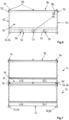
- Fig. 2 shows a possible arrangement of containers 10 for loading the loading area 4 of the vehicle 2, whereby the first side length S 1 of the base area G of the container 10, based on the width dimension Y of the loading area 4, has a divisor of 1 and the second side length S 2 of the base area , based on the length of the loading area 4, has a divider of at least 3.
- the second side length S 2 of the base area of the container 10 is adapted to the length X of the loading area 4 in such a way that it corresponds to an integer divisor of approximately four. This will make how Fig. 2 clarifies, a row of several, a total of four containers 10 arranged one behind the other are arranged in one plane on the loading area 4 of the vehicle 2.
- Fig. 3 shows a possible further arrangement of containers 10 for loading the loading area 4 of a vehicle 2 with containers 10, the second side length S 2 of the base area G of the container 10, based on the width dimension Y of the loading area, being a divider of 2 and the first side length S 1 of the base area G of the container 10, based on the length X of the loading area 4, has a divisor of at least 2 or more.
- the loading area 4 two adjacent rows of two or more, in the present case three, containers 10 arranged next to one another can be arranged in one plane on the loading area 4.
- the second side length S 2 of the base area G of the container 10 essentially corresponds to half of the width dimension Y of the loading area.
- the loading area 4 is at least 95% utilized by the containers 10.
- FIG. 4 to 6 An embodiment of a container 10 according to the invention is shown, which has a container base 12, a plurality of side walls 14, 14 ', 16, 16' and a container ceiling 18.
- the container bottom 12, the side walls 14 - 16 'and the container ceiling 18 form a receiving space 20 for dangerous goods that can be positioned within the container 10.
- the container 10 has a movable flap part 22 as access to the receiving space 20.
- the flap part 22 can be moved back and forth between a closed position and an open position.
- a loading floor 24 is arranged as a receiving surface for the dangerous goods, which is arranged at a distance above the container floor 12.
- the loading floor 24 is formed, for example, from several, in particular four, gratings 26, which are arranged running in one plane.
- the container 10 has a connection 28 on its rear side wall 14 'for introducing coolant or extinguishing agent into the receiving space 20.
- the connection 28 designed as an inlet is in the present case arranged approximately at the height of the container ceiling 18, but at least halfway up the side wall 14 ', so that a coolant or extinguishing agent introduced into the receiving space 20 can be released onto the top of a dangerous goods arranged in the container.
- connection 30 for discharging coolant or extinguishing agent from the receiving space 10 is provided on the container 10.
- the connection 30 is arranged on the rear side wall 14 'of the container 10.
- connections 28, 30 are arranged set back in or behind the plane spanning the container walls 14 - 16 '. The connections therefore do not protrude outwards on the container walls.
- the connections 28, 30 also each have Storz couplings for connecting fluid hoses.
- a collecting trough 38 is formed below the loading floor 24 for the coolant or extinguishing agent introduced into the receiving space 20 of the container 10.
- the collecting trough 38 is formed from the container bottom 12 and sections of the container walls 14 - 16 'running perpendicular thereto.
- An extinguishing agent reservoir 40 is arranged within the container 10 and is designed to release the extinguishing agent located in the reservoir 40 into the receiving space 20 after activation.
- the extinguishing agent reservoir 40 can be fluidly coupled to an extinguishing nozzle arranged in the receiving space 20.
- the extinguishing agent reservoir can be activated by means of a sensor element arranged in the receiving space, such as a thermally activated thermocouple. In the embodiment shown this will be the case Extinguishing agent reservoir activated manually by means of a cable 41 from the outside of the container 10.
- an openable and closable ventilation opening 42 is provided on the side wall 16 ', via which gases can be sucked out of the receiving space 10 of the container.
- the flap part 22 which forms access to the receiving space 20 forms wall areas of the front side wall 14 and the container ceiling 18 of the container 10.
- the flap part 22 is formed in particular from two plate parts 44, 46 which run perpendicular to one another and are rigidly connected to one another.
- the flap part 22 is received by means of a pivot bearing 48 which runs parallel to the container ceiling and the side lengths S 1 .
- the pivot bearing 48 is formed at the height of the container ceiling 18 and in the depth direction of the container 10 on half of the container ceiling.
- the loading aid 50 is designed as a forklift pocket, the loading aid 52 as a lifting eye and the loading aid 54 as a loading receptacle.
- the laterally projecting loading aids 54 serve as spacers between transport or quarantine containers 10 arranged adjacently on the loading area.
- the flap part 22 is held in its closed position in the closed position by means of locking means 56, 58 which correspond to one another and are arranged on the flap part 22 and at least the side walls 16, 16 '.
- two or more transport or quarantine containers 10 can be stacked one on top of the other, with several positioning means 32, 34 arranged on the container bottom 12 and container ceiling 18 being provided on the containers for stacking several containers 10 in levels one above the other.
- the positioning means 32, 34 protrude perpendicularly from the plane spanning the container bottom 12 and the container ceiling 18.
- the positioning means 32 on the container bottom 12 can be designed as a receptacle corresponding to the positioning means 34.
- the positioning means 32 are in particular formed on the support feet 36 protruding from the container base 12.
- the positioning means 34 on the container ceiling 18 can be designed as a locking part that projects approximately vertically therefrom.
- the containers 10 have a defined height H, so that two containers 10 stacked one above the other on the loading area 4 of the vehicle 2 have a loading height L, which is below the permissible loading height of the vehicle 2 when the containers 10 are loaded.
Landscapes
- Engineering & Computer Science (AREA)
- Transportation (AREA)
- Mechanical Engineering (AREA)
- Details Of Rigid Or Semi-Rigid Containers (AREA)
Priority Applications (1)
| Application Number | Priority Date | Filing Date | Title |
|---|---|---|---|
| EP22172857.9A EP4275952A1 (fr) | 2022-05-11 | 2022-05-11 | Système de transport comprenant un véhicule et un récipient de transport et de quarantaine |
Applications Claiming Priority (1)
| Application Number | Priority Date | Filing Date | Title |
|---|---|---|---|
| EP22172857.9A EP4275952A1 (fr) | 2022-05-11 | 2022-05-11 | Système de transport comprenant un véhicule et un récipient de transport et de quarantaine |
Publications (1)
| Publication Number | Publication Date |
|---|---|
| EP4275952A1 true EP4275952A1 (fr) | 2023-11-15 |
Family
ID=81603533
Family Applications (1)
| Application Number | Title | Priority Date | Filing Date |
|---|---|---|---|
| EP22172857.9A Pending EP4275952A1 (fr) | 2022-05-11 | 2022-05-11 | Système de transport comprenant un véhicule et un récipient de transport et de quarantaine |
Country Status (1)
| Country | Link |
|---|---|
| EP (1) | EP4275952A1 (fr) |
Citations (6)
| Publication number | Priority date | Publication date | Assignee | Title |
|---|---|---|---|---|
| WO2001070597A1 (fr) * | 2000-03-21 | 2001-09-27 | Fleet Tanks (Uk) Limited | Reservoir pour matieres dangereuses |
| JP2003312774A (ja) * | 2002-04-26 | 2003-11-06 | Nippon Sharyo Seizo Kaisha Ltd | 廃棄物用コンテナ |
| DE202009010748U1 (de) * | 2009-08-10 | 2009-12-10 | Css-Patentverwaltungsgesellschaft Mbh | Vorrichtung zum Transport und/oder zur Lagerung von Gefahrgütern/Gefahrstoffen |
| WO2014194876A1 (fr) | 2013-06-02 | 2014-12-11 | Markus Kohten | Contenant de sécurité pour marchandises dangereuses, en particulier pour des batteries |
| CN107406023B (zh) * | 2015-03-31 | 2020-04-24 | 世纪阿科玛株式会社 | 危险品保管装置 |
| US20210331010A1 (en) * | 2018-10-05 | 2021-10-28 | Jun-ho Hwang | Pipe-type fire extinguishing equipment for extinguishing fire inside ship transport container |
-
2022
- 2022-05-11 EP EP22172857.9A patent/EP4275952A1/fr active Pending
Patent Citations (6)
| Publication number | Priority date | Publication date | Assignee | Title |
|---|---|---|---|---|
| WO2001070597A1 (fr) * | 2000-03-21 | 2001-09-27 | Fleet Tanks (Uk) Limited | Reservoir pour matieres dangereuses |
| JP2003312774A (ja) * | 2002-04-26 | 2003-11-06 | Nippon Sharyo Seizo Kaisha Ltd | 廃棄物用コンテナ |
| DE202009010748U1 (de) * | 2009-08-10 | 2009-12-10 | Css-Patentverwaltungsgesellschaft Mbh | Vorrichtung zum Transport und/oder zur Lagerung von Gefahrgütern/Gefahrstoffen |
| WO2014194876A1 (fr) | 2013-06-02 | 2014-12-11 | Markus Kohten | Contenant de sécurité pour marchandises dangereuses, en particulier pour des batteries |
| CN107406023B (zh) * | 2015-03-31 | 2020-04-24 | 世纪阿科玛株式会社 | 危险品保管装置 |
| US20210331010A1 (en) * | 2018-10-05 | 2021-10-28 | Jun-ho Hwang | Pipe-type fire extinguishing equipment for extinguishing fire inside ship transport container |
Similar Documents
| Publication | Publication Date | Title |
|---|---|---|
| DE102020101243B3 (de) | Transportkiste für defekte Batterien | |
| DE19741203C2 (de) | Belüftetes Käfig- und Gestellsystem | |
| DE202019104504U1 (de) | Behälter zum Aufnehmen von Gefahrgütern | |
| EP2822609A1 (fr) | Récipient de stérilisation chirurgical et dispositif d'extraction de fluides chirurgical | |
| DE102012108652A1 (de) | Staubsauger | |
| DE202013004963U1 (de) | Sicherheitsbox zum Transport und Lagerung von Batterien | |
| EP3285973A1 (fr) | Réceptacle de rangement | |
| EP2774866A1 (fr) | Récipient destiné à recevoir des petites pièces | |
| DE102018123691B4 (de) | Gehäuse | |
| DE102016010891A1 (de) | Vorrichtung und Verfahren zum Austausch von austauschbaren Komponenten einer Windenergieanlage | |
| EP2822608B1 (fr) | Cuve pour récipient de stérilisation à usage chirurgical avec sortie de condense | |
| DE202017107317U1 (de) | Stapelbarer Systembehälter und Transportsystem | |
| DE102011013844A1 (de) | Transportgestell für den Triebstrang einer Windenergieanlage | |
| EP4275952A1 (fr) | Système de transport comprenant un véhicule et un récipient de transport et de quarantaine | |
| EP2132849B1 (fr) | Distributeur souterrain | |
| DE202013003740U1 (de) | Werkzeugverstauungsbehälter | |
| DE102014100321B4 (de) | Gekühltes Aufbewahrungssystem | |
| EP2213966B1 (fr) | Dispositif de conditionnement de la température pour un récipient de transport d'aliments | |
| EP3738898B1 (fr) | Récipient pour marchandises dangereuses | |
| DE202017102440U1 (de) | Vorrichtung zur Aufnahme von Gefahrstoffen | |
| WO2012130573A2 (fr) | Appareil frigorifique | |
| DE2407689C3 (fr) | ||
| DE102012006478A1 (de) | Kühlmittelbehälter, Vorrichtung und Verfahren zur Temperaturhaltung | |
| DE102022120627B4 (de) | Einhausung von Wärmepumpen | |
| DE102024205521A1 (de) | Energiespeichersystem |
Legal Events
| Date | Code | Title | Description |
|---|---|---|---|
| PUAI | Public reference made under article 153(3) epc to a published international application that has entered the european phase |
Free format text: ORIGINAL CODE: 0009012 |
|
| STAA | Information on the status of an ep patent application or granted ep patent |
Free format text: STATUS: THE APPLICATION HAS BEEN PUBLISHED |
|
| AK | Designated contracting states |
Kind code of ref document: A1 Designated state(s): AL AT BE BG CH CY CZ DE DK EE ES FI FR GB GR HR HU IE IS IT LI LT LU LV MC MK MT NL NO PL PT RO RS SE SI SK SM TR |
|
| STAA | Information on the status of an ep patent application or granted ep patent |
Free format text: STATUS: REQUEST FOR EXAMINATION WAS MADE |
|
| 17P | Request for examination filed |
Effective date: 20240515 |
|
| RBV | Designated contracting states (corrected) |
Designated state(s): AL AT BE BG CH CY CZ DE DK EE ES FI FR GB GR HR HU IE IS IT LI LT LU LV MC MK MT NL NO PL PT RO RS SE SI SK SM TR |
|
| STAA | Information on the status of an ep patent application or granted ep patent |
Free format text: STATUS: EXAMINATION IS IN PROGRESS |
|
| 17Q | First examination report despatched |
Effective date: 20250703 |
|
| GRAP | Despatch of communication of intention to grant a patent |
Free format text: ORIGINAL CODE: EPIDOSNIGR1 |
|
| STAA | Information on the status of an ep patent application or granted ep patent |
Free format text: STATUS: GRANT OF PATENT IS INTENDED |