EP4275960A1 - Procédé de montage sans défaut d'un composant électronique - Google Patents
Procédé de montage sans défaut d'un composant électronique Download PDFInfo
- Publication number
- EP4275960A1 EP4275960A1 EP23163362.9A EP23163362A EP4275960A1 EP 4275960 A1 EP4275960 A1 EP 4275960A1 EP 23163362 A EP23163362 A EP 23163362A EP 4275960 A1 EP4275960 A1 EP 4275960A1
- Authority
- EP
- European Patent Office
- Prior art keywords
- component
- adapter element
- locking device
- plug
- sensor
- Prior art date
- Legal status (The legal status is an assumption and is not a legal conclusion. Google has not performed a legal analysis and makes no representation as to the accuracy of the status listed.)
- Granted
Links
Images


Classifications
-
- G—PHYSICS
- G01—MEASURING; TESTING
- G01D—MEASURING NOT SPECIALLY ADAPTED FOR A SPECIFIC VARIABLE; ARRANGEMENTS FOR MEASURING TWO OR MORE VARIABLES NOT COVERED IN A SINGLE OTHER SUBCLASS; TARIFF METERING APPARATUS; MEASURING OR TESTING NOT OTHERWISE PROVIDED FOR
- G01D11/00—Component parts of measuring arrangements not specially adapted for a specific variable
- G01D11/30—Supports specially adapted for an instrument; Supports specially adapted for a set of instruments
-
- B—PERFORMING OPERATIONS; TRANSPORTING
- B60—VEHICLES IN GENERAL
- B60R—VEHICLES, VEHICLE FITTINGS, OR VEHICLE PARTS, NOT OTHERWISE PROVIDED FOR
- B60R19/00—Wheel guards; Radiator guards, e.g. grilles; Obstruction removers; Fittings damping bouncing force in collisions
- B60R19/02—Bumpers, i.e. impact receiving or absorbing members for protecting vehicles or fending off blows from other vehicles or objects
- B60R19/48—Bumpers, i.e. impact receiving or absorbing members for protecting vehicles or fending off blows from other vehicles or objects combined with, or convertible into, other devices or objects, e.g. bumpers combined with road brushes, bumpers convertible into beds
- B60R19/483—Bumpers, i.e. impact receiving or absorbing members for protecting vehicles or fending off blows from other vehicles or objects combined with, or convertible into, other devices or objects, e.g. bumpers combined with road brushes, bumpers convertible into beds with obstacle sensors of electric or electronic type
-
- G—PHYSICS
- G01—MEASURING; TESTING
- G01S—RADIO DIRECTION-FINDING; RADIO NAVIGATION; DETERMINING DISTANCE OR VELOCITY BY USE OF RADIO WAVES; LOCATING OR PRESENCE-DETECTING BY USE OF THE REFLECTION OR RERADIATION OF RADIO WAVES; ANALOGOUS ARRANGEMENTS USING OTHER WAVES
- G01S7/00—Details of systems according to groups G01S13/00, G01S15/00, G01S17/00
- G01S7/52—Details of systems according to groups G01S13/00, G01S15/00, G01S17/00 of systems according to group G01S15/00
- G01S7/521—Constructional features
-
- G—PHYSICS
- G01—MEASURING; TESTING
- G01S—RADIO DIRECTION-FINDING; RADIO NAVIGATION; DETERMINING DISTANCE OR VELOCITY BY USE OF RADIO WAVES; LOCATING OR PRESENCE-DETECTING BY USE OF THE REFLECTION OR RERADIATION OF RADIO WAVES; ANALOGOUS ARRANGEMENTS USING OTHER WAVES
- G01S13/00—Systems using the reflection or reradiation of radio waves, e.g. radar systems; Analogous systems using reflection or reradiation of waves whose nature or wavelength is irrelevant or unspecified
- G01S13/88—Radar or analogous systems specially adapted for specific applications
- G01S13/93—Radar or analogous systems specially adapted for specific applications for anti-collision purposes
- G01S13/931—Radar or analogous systems specially adapted for specific applications for anti-collision purposes of land vehicles
- G01S2013/9327—Sensor installation details
- G01S2013/93275—Sensor installation details in the bumper area
-
- G—PHYSICS
- G01—MEASURING; TESTING
- G01S—RADIO DIRECTION-FINDING; RADIO NAVIGATION; DETERMINING DISTANCE OR VELOCITY BY USE OF RADIO WAVES; LOCATING OR PRESENCE-DETECTING BY USE OF THE REFLECTION OR RERADIATION OF RADIO WAVES; ANALOGOUS ARRANGEMENTS USING OTHER WAVES
- G01S15/00—Systems using the reflection or reradiation of acoustic waves, e.g. sonar systems
- G01S15/88—Sonar systems specially adapted for specific applications
- G01S15/93—Sonar systems specially adapted for specific applications for anti-collision purposes
- G01S15/931—Sonar systems specially adapted for specific applications for anti-collision purposes of land vehicles
- G01S2015/937—Sonar systems specially adapted for specific applications for anti-collision purposes of land vehicles sensor installation details
- G01S2015/938—Sonar systems specially adapted for specific applications for anti-collision purposes of land vehicles sensor installation details in the bumper area
Definitions
- the adapter element can, for example, be firmly attached to the thermoplastic external vehicle attachment part by means of a welding process and serves to mount the electronic component on the external attachment part in a precise position.
- PDC sensors Park Distance Control
- PTS sensors Park Tronic System
- a method for correctly mounting a sensor on a motor vehicle using an adapter element is from DE 10 2018 104 715 B4 known.
- the aim of this method is to avoid unnoticed incorrect positioning of the sensor in the adapter element.
- the invention is based on the object of specifying a method with the features described above, which ensures that the correct type of electronic component with an axially aligned plug is actually installed.
- the locking device is designed in such a way that it does not hinder the proper installation of the correct electronic component with a parallel-aligned plug, but does prevent the accidental installation of an analog component with a radially aligned plug. In concrete terms, this means that the locking device "stands in the way" of a component with a radially aligned plug during component assembly, which is not the case with a component with an axially aligned plug.
- analog component means in particular that the electronic component in question here with an axially aligned plug basically has the same function as the corresponding electronic component with a radially aligned plug, for example in both cases it is a PDC sensor.
- the two components differ in terms of their housing geometry only in the housing circumferential area of the plug connection, but are otherwise at least essentially or even completely identical.
- the locking device is dimensioned such that it is spaced from this component when the component with an axial plug is mounted.
- the adapter element expediently has an opening through which the component passes during assembly, with the locking device being provided on the inside in the edge region of the opening.
- the locking device is expediently designed in such a way that, with regard to the "correct" component with an axial plug, it (only) engages in a free space which, in the assembled state, is shared by this component and the adapter element is formed.
- the locking device is located in an area that is actually occupied by the "wrong" component in its assembly position, so that an incorrect attempt at assembly leads to a collision between the locking device and the wrong component This makes the assembly error noticeable. Incorrect assembly is therefore reliably prevented by the teaching according to the invention.
- the locking device is aligned at least substantially parallel to the component axis.
- the locking device in the assembled state of the correct component, can be arranged parallel and spaced from the housing of the component running in the axial direction.
- the locking device partially fills a free space formed by the adapter element and the parallel-aligned plug in the assembled state and protrudes up to the plug, but does not touch it.
- a free space is not available if a component with a radial plug is accidentally installed, so that the locking device collides with this incorrect component plug during assembly.
- the adapter element can be produced by injection molding and the locking device can be integrally formed onto the adapter element. This allows a particularly cost-effective provision of the locking device, with the adapter element preferably being designed as a polymer component.
- the locking device projects towards the inside of the motor vehicle and is preferably designed as a combination of several ribs spaced apart from one another. Within the scope of the invention, it is particularly important that the locking device protrudes inwards with a height of at least 2 mm.
- the adapter element is expediently provided with a stop surface which is spaced apart from the locking device and against which the component comes into contact during the assembly process.
- the stop of the component against this stop surface expediently ends the assembly movement, whereby this assembly movement is not influenced by the locking device when the correct component is assembled with an axial plug, but it is when the wrong component is mounted with a radial plug.
- the sensor is preferably designed as a PDC sensor and/or the external attachment as a vehicle bumper.
- the invention furthermore relates to an adapter element for carrying out the method according to claim 9 and a component group according to claim 10.
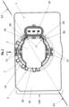
- the Figure 1 shows a component group 100 consisting of an adapter element 3 and an electronic component 2, which in the exemplary embodiment is designed as a PDC sensor.
- the adapter element 3 serves to accommodate and error-free installation of the sensor 2 on a polymeric external attachment 1 in the form of a bumper of a motor vehicle.
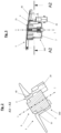
- the sensor 2 is parallel to the component axis x (see Fig. 2, 3 ) aligned plug 20 for electrical contacting of the sensor 2.
- the adapter element 3 has a receiving device 10 having a circular opening 6 (see Fig. Fig.
- the opening 6 of the adapter element 3 is covered by the sensor 2 during assembly (see also the outer end face 25 of the sensor 2 in Fig. 3 ).
- this receiving device 10 has a connecting device 50 in the form of a welding flange.
- a locking device 4 on the adapter element 3 prevents the accidental installation of an analog sensor 2' with a plug 20' aligned radially to the component axis x' (see Fig. Fig. 5 ).
- the sensors 2 and 2' differ in terms of their housing geometry only in the respective inside area 300 and 300', i.e. the peripheral area of the housing respective plug connection.
- the locking device 4 is designed in such a way that, when the sensor 2 is mounted with an axially parallel plug 20, it is positioned in the immediate vicinity of this plug 20, but does not touch it and is therefore separated from this plug 20 - even if only slightly at a distance of, for example, ⁇ 1 mm - is spaced apart.
- the correct installation of the correct sensor 2 with an axially aligned plug 20 is not hindered by the locking device 4, but the accidental installation of an analog sensor 2 'with a radially aligned plug 20' is.
- the locking device 4 is like that Figure 5 can be seen - in the event of accidental assembly of a sensor 2 'with a radially aligned plug 20', this sensor 2' is, so to speak, "in the way", which is not the case with the sensor 2 with an axially aligned plug 20.
- Fig. 1 and 4 show that for fixing the sensor 2 on the adapter element 3 locking elements 15 are provided.
- the locking device 4 is designed so that it engages with respect to the "correct" sensor 20 with an axial plug 2 in a free space 80, which in the assembled state is formed together by this plug 2 and the adapter element 3.
- the locking device 4 is located in an area that is normally occupied by the mounted sensor 20' (see Fig. Fig. 5 ).
- the sensor 2 ' has a radial plug 20' with a housing 200', which is on the same side as the axial plug 20 according to Fig. 1 to 3 .
- the locking device 4 will collide with its radial plug 20'.
- the locking device 4 fills the free space 80 formed by the adapter element 3 and the parallel-aligned plug 20 (see Fig. Fig. 1 ) in some areas and extends directly to the plug 20, but does not touch it.
- a free space 80 is necessary if the sensor 2' is accidentally installed with the radial plug 20' ( Fig.
- the locking device 4 is directed towards the inside of the motor vehicle I (see Fig. Fig. 2, 3 ) and protrudes inwards from the adapter element 3.
- the adapter element 3 is designed as a polymer component produced by injection molding and the locking device 4 was integrally formed onto the adapter element 3.
- the locking device 4 is designed as a combination of two ribs 40 spaced apart from one another, projecting towards the inside of the motor vehicle I with a height h of at least 2 mm (see in particular Fig. 1 and 3 ). When assembled, the plug 20 is at least partially arranged between these two ribs 40.
- FIG. 1 A comparative view of the Figures 1 to 4 It can be seen that the locking device 4 is arranged in the edge region 7 of the opening 6 and is missing on the opposite side 60 of this edge region 7 rotated through 180 °, while on this opposite side 60 of the receiving device 10 a stop surface 8 for the sensor 2 is provided . Accordingly, this stop surface 8 is arranged at a distance from the locking device 4. During the assembly process, the sensor 2 comes into contact with the stop surface 8. The stop of the sensor 2 against this stop surface 8 ends the assembly movement, this assembly movement not being hindered by the locking device 4 when the correct sensor 2 with axial plug 20 is being installed.
Landscapes
- Engineering & Computer Science (AREA)
- Physics & Mathematics (AREA)
- General Physics & Mathematics (AREA)
- Computer Networks & Wireless Communication (AREA)
- Radar, Positioning & Navigation (AREA)
- Remote Sensing (AREA)
- Mechanical Engineering (AREA)
- Details Of Connecting Devices For Male And Female Coupling (AREA)
Applications Claiming Priority (1)
| Application Number | Priority Date | Filing Date | Title |
|---|---|---|---|
| DE102022111437.6A DE102022111437A1 (de) | 2022-05-09 | 2022-05-09 | Verfahren zur fehlerfreien Montage eines elektronischen Bauteils |
Publications (2)
| Publication Number | Publication Date |
|---|---|
| EP4275960A1 true EP4275960A1 (fr) | 2023-11-15 |
| EP4275960B1 EP4275960B1 (fr) | 2025-11-05 |
Family
ID=85724699
Family Applications (1)
| Application Number | Title | Priority Date | Filing Date |
|---|---|---|---|
| EP23163362.9A Active EP4275960B1 (fr) | 2022-05-09 | 2023-03-22 | Procédé de montage sans défaut d'un composant électronique |
Country Status (2)
| Country | Link |
|---|---|
| EP (1) | EP4275960B1 (fr) |
| DE (1) | DE102022111437A1 (fr) |
Citations (5)
| Publication number | Priority date | Publication date | Assignee | Title |
|---|---|---|---|---|
| DE19819698A1 (de) * | 1998-05-02 | 1999-11-11 | Daimler Chrysler Ag | Befestigungseinrichtung an einem Anbauteil für ein Kraftfahrzeug |
| DE10156049A1 (de) * | 2000-11-17 | 2002-09-12 | Trw Automotive Electron & Comp | Gehäuse für sicherheitsrelevante Steuergeräte in Kraftfahrzeugen |
| EP1555163A1 (fr) * | 2004-01-13 | 2005-07-20 | Meta System S.p.A. | Unité pour détecter la présence d'obstacles au voisinage d' un véhicules |
| EP1785316A1 (fr) * | 2005-11-12 | 2007-05-16 | Nissan Motor Manufacturing (UK) Ltd. | Fixation pour détecteurs d'aide au stationnement de véhicule |
| DE102018104715B4 (de) | 2018-03-01 | 2022-01-27 | Valeo Schalter Und Sensoren Gmbh | Sensorhalter zur Befestigung eines Sensors an einem Kraftfahrzeug |
Family Cites Families (2)
| Publication number | Priority date | Publication date | Assignee | Title |
|---|---|---|---|---|
| DE102008048318A1 (de) | 2008-09-22 | 2010-09-23 | Audi Ag | Befestigungsvorrichtung und Verfahren zum Befestigen in einer Öffnung in einer Wand |
| DE102017117926A1 (de) | 2017-08-07 | 2019-02-07 | Huf Hülsbeck & Fürst Gmbh & Co. Kg | Türgriffmodul |
-
2022
- 2022-05-09 DE DE102022111437.6A patent/DE102022111437A1/de active Pending
-
2023
- 2023-03-22 EP EP23163362.9A patent/EP4275960B1/fr active Active
Patent Citations (5)
| Publication number | Priority date | Publication date | Assignee | Title |
|---|---|---|---|---|
| DE19819698A1 (de) * | 1998-05-02 | 1999-11-11 | Daimler Chrysler Ag | Befestigungseinrichtung an einem Anbauteil für ein Kraftfahrzeug |
| DE10156049A1 (de) * | 2000-11-17 | 2002-09-12 | Trw Automotive Electron & Comp | Gehäuse für sicherheitsrelevante Steuergeräte in Kraftfahrzeugen |
| EP1555163A1 (fr) * | 2004-01-13 | 2005-07-20 | Meta System S.p.A. | Unité pour détecter la présence d'obstacles au voisinage d' un véhicules |
| EP1785316A1 (fr) * | 2005-11-12 | 2007-05-16 | Nissan Motor Manufacturing (UK) Ltd. | Fixation pour détecteurs d'aide au stationnement de véhicule |
| DE102018104715B4 (de) | 2018-03-01 | 2022-01-27 | Valeo Schalter Und Sensoren Gmbh | Sensorhalter zur Befestigung eines Sensors an einem Kraftfahrzeug |
Also Published As
| Publication number | Publication date |
|---|---|
| EP4275960B1 (fr) | 2025-11-05 |
| DE102022111437A1 (de) | 2023-11-09 |
Similar Documents
| Publication | Publication Date | Title |
|---|---|---|
| EP0816151B1 (fr) | Réservoir de carburant | |
| DE102017106681A1 (de) | Bolzenclipeinsatz für Plattenbohrung | |
| DE112012001539B4 (de) | Formwerkzeug und Formverfahren für ein aus Harz geformtes Produkt | |
| DE102007023070B4 (de) | Ausgleichsbehälter für eine hydraulische Kraftfahrzeugbremsanlage | |
| DE102010015179A1 (de) | Anordnung zur Befestigung von Fahrzeugbauteilen an einer Rohbaukarosserie eines Fahrzeugs | |
| DE102018108830A1 (de) | System aus einem Anbauteil und einem Halteelement | |
| DE102004025698B4 (de) | Rastverbinder und Verfahren zur Qualitätskontrolle einer Rastverbindung | |
| DE102009013988A1 (de) | Spritzwand mit Kupplungsgeberzylinder | |
| EP2682615B1 (fr) | Ecrou | |
| DE102014115008A1 (de) | Vorrichtung zum positionsgerechten Befestigen einer Antennenanordnung an einer Fläche | |
| DE102013007036A1 (de) | Kontaktiereinrichtung für eine elektrische Kontaktanordnung sowie Verfahren zu deren Herstellung | |
| EP4275960A1 (fr) | Procédé de montage sans défaut d'un composant électronique | |
| EP1728259A1 (fr) | Dispositif pour surveiller le niveau de remplissage d'un contenant | |
| EP2588766B1 (fr) | Dispositif de fixation | |
| EP4276420A1 (fr) | Procédé de montage sans défaut d'un composant électronique | |
| DE102014009257A1 (de) | Exzenterelement und Verfahren zum Einstellen einer Relativposition eines Anbauteils | |
| DE102004050674B4 (de) | Befestigungsanordnung für elektrische Komponenten in einem Fahrzeug | |
| DE102004048436A1 (de) | Steckhülse zur Befestigung eines Bauteils in einer Bohrung | |
| DE102019104767A1 (de) | Montageanordnung, Verwendung einer Montagevorrichtung sowie Montageverfahren | |
| EP4093995B1 (fr) | Élément d'étanchéité pour un module de capteur de pression pour véhicule automobile et module de capteur de pression | |
| DE102017119230A1 (de) | Befestigungssystem zur Befestigung eines Sensors eines Fahrassistenzsystems | |
| DE102021200824B4 (de) | Kraftstofffördervorrichtung und Kraftstofftank mit einer derartigen Kraftstofffördervorrichtung | |
| DE102012023044B4 (de) | Befestigungsvorrichtung für ein Kunststoffbauteil | |
| WO2018149543A1 (fr) | Dispositif pour assurer le montage d'un composant à son emplacement d'installation prévu | |
| DE102018130537A1 (de) | Tankeinfüllsystem eines Fahrzeugs und Verfahren zur Montage eines Tankeinfüllsystems |
Legal Events
| Date | Code | Title | Description |
|---|---|---|---|
| PUAI | Public reference made under article 153(3) epc to a published international application that has entered the european phase |
Free format text: ORIGINAL CODE: 0009012 |
|
| STAA | Information on the status of an ep patent application or granted ep patent |
Free format text: STATUS: THE APPLICATION HAS BEEN PUBLISHED |
|
| AK | Designated contracting states |
Kind code of ref document: A1 Designated state(s): AL AT BE BG CH CY CZ DE DK EE ES FI FR GB GR HR HU IE IS IT LI LT LU LV MC ME MK MT NL NO PL PT RO RS SE SI SK SM TR |
|
| STAA | Information on the status of an ep patent application or granted ep patent |
Free format text: STATUS: REQUEST FOR EXAMINATION WAS MADE |
|
| 17P | Request for examination filed |
Effective date: 20240325 |
|
| RBV | Designated contracting states (corrected) |
Designated state(s): AL AT BE BG CH CY CZ DE DK EE ES FI FR GB GR HR HU IE IS IT LI LT LU LV MC ME MK MT NL NO PL PT RO RS SE SI SK SM TR |
|
| STAA | Information on the status of an ep patent application or granted ep patent |
Free format text: STATUS: EXAMINATION IS IN PROGRESS |
|
| 17Q | First examination report despatched |
Effective date: 20241125 |
|
| REG | Reference to a national code |
Ref legal event code: R079 Ipc: G01S0007521000 Ref country code: DE Ref legal event code: R079 Ref document number: 502023002125 Country of ref document: DE Free format text: PREVIOUS MAIN CLASS: B60R0011000000 Ipc: G01S0007521000 |
|
| GRAP | Despatch of communication of intention to grant a patent |
Free format text: ORIGINAL CODE: EPIDOSNIGR1 |
|
| STAA | Information on the status of an ep patent application or granted ep patent |
Free format text: STATUS: GRANT OF PATENT IS INTENDED |
|
| RIC1 | Information provided on ipc code assigned before grant |
Ipc: G01S 7/521 20060101AFI20250623BHEP Ipc: G01S 13/931 20200101ALI20250623BHEP Ipc: G01S 15/931 20200101ALI20250623BHEP Ipc: G01D 11/30 20060101ALI20250623BHEP Ipc: B60R 19/48 20060101ALI20250623BHEP |
|
| INTG | Intention to grant announced |
Effective date: 20250702 |
|
| RAP3 | Party data changed (applicant data changed or rights of an application transferred) |
Owner name: RESRG AUTOMOTIVE SE & CO. KG |
|
| GRAS | Grant fee paid |
Free format text: ORIGINAL CODE: EPIDOSNIGR3 |
|
| GRAA | (expected) grant |
Free format text: ORIGINAL CODE: 0009210 |
|
| STAA | Information on the status of an ep patent application or granted ep patent |
Free format text: STATUS: THE PATENT HAS BEEN GRANTED |
|
| AK | Designated contracting states |
Kind code of ref document: B1 Designated state(s): AL AT BE BG CH CY CZ DE DK EE ES FI FR GB GR HR HU IE IS IT LI LT LU LV MC ME MK MT NL NO PL PT RO RS SE SI SK SM TR |
|
| REG | Reference to a national code |
Ref country code: CH Ref legal event code: F10 Free format text: ST27 STATUS EVENT CODE: U-0-0-F10-F00 (AS PROVIDED BY THE NATIONAL OFFICE) Effective date: 20251105 Ref country code: GB Ref legal event code: FG4D Free format text: NOT ENGLISH |
|
| REG | Reference to a national code |
Ref country code: DE Ref legal event code: R096 Ref document number: 502023002125 Country of ref document: DE |
|
| REG | Reference to a national code |
Ref country code: IE Ref legal event code: FG4D Free format text: LANGUAGE OF EP DOCUMENT: GERMAN |
|
| REG | Reference to a national code |
Ref country code: NL Ref legal event code: MP Effective date: 20251105 |
|
| PG25 | Lapsed in a contracting state [announced via postgrant information from national office to epo] |
Ref country code: ES Free format text: LAPSE BECAUSE OF FAILURE TO SUBMIT A TRANSLATION OF THE DESCRIPTION OR TO PAY THE FEE WITHIN THE PRESCRIBED TIME-LIMIT Effective date: 20251105 |
|
| REG | Reference to a national code |
Ref country code: LT Ref legal event code: MG9D |
|
| PG25 | Lapsed in a contracting state [announced via postgrant information from national office to epo] |
Ref country code: NO Free format text: LAPSE BECAUSE OF FAILURE TO SUBMIT A TRANSLATION OF THE DESCRIPTION OR TO PAY THE FEE WITHIN THE PRESCRIBED TIME-LIMIT Effective date: 20260205 |
|
| PGFP | Annual fee paid to national office [announced via postgrant information from national office to epo] |
Ref country code: DE Payment date: 20260331 Year of fee payment: 4 |
|
| PG25 | Lapsed in a contracting state [announced via postgrant information from national office to epo] |
Ref country code: FI Free format text: LAPSE BECAUSE OF FAILURE TO SUBMIT A TRANSLATION OF THE DESCRIPTION OR TO PAY THE FEE WITHIN THE PRESCRIBED TIME-LIMIT Effective date: 20251105 Ref country code: HR Free format text: LAPSE BECAUSE OF FAILURE TO SUBMIT A TRANSLATION OF THE DESCRIPTION OR TO PAY THE FEE WITHIN THE PRESCRIBED TIME-LIMIT Effective date: 20251105 |
|
| PGFP | Annual fee paid to national office [announced via postgrant information from national office to epo] |
Ref country code: AT Payment date: 20260301 Year of fee payment: 4 |
|
| PG25 | Lapsed in a contracting state [announced via postgrant information from national office to epo] |
Ref country code: NL Free format text: LAPSE BECAUSE OF FAILURE TO SUBMIT A TRANSLATION OF THE DESCRIPTION OR TO PAY THE FEE WITHIN THE PRESCRIBED TIME-LIMIT Effective date: 20251105 |
|
| PG25 | Lapsed in a contracting state [announced via postgrant information from national office to epo] |
Ref country code: RS Free format text: LAPSE BECAUSE OF FAILURE TO SUBMIT A TRANSLATION OF THE DESCRIPTION OR TO PAY THE FEE WITHIN THE PRESCRIBED TIME-LIMIT Effective date: 20260205 |
|
| PG25 | Lapsed in a contracting state [announced via postgrant information from national office to epo] |
Ref country code: IS Free format text: LAPSE BECAUSE OF FAILURE TO SUBMIT A TRANSLATION OF THE DESCRIPTION OR TO PAY THE FEE WITHIN THE PRESCRIBED TIME-LIMIT Effective date: 20260305 |
|
| PGFP | Annual fee paid to national office [announced via postgrant information from national office to epo] |
Ref country code: FR Payment date: 20260213 Year of fee payment: 4 |
|
| PG25 | Lapsed in a contracting state [announced via postgrant information from national office to epo] |
Ref country code: PT Free format text: LAPSE BECAUSE OF FAILURE TO SUBMIT A TRANSLATION OF THE DESCRIPTION OR TO PAY THE FEE WITHIN THE PRESCRIBED TIME-LIMIT Effective date: 20260305 |
|
| PG25 | Lapsed in a contracting state [announced via postgrant information from national office to epo] |
Ref country code: PL Free format text: LAPSE BECAUSE OF FAILURE TO SUBMIT A TRANSLATION OF THE DESCRIPTION OR TO PAY THE FEE WITHIN THE PRESCRIBED TIME-LIMIT Effective date: 20251105 |
|
| PG25 | Lapsed in a contracting state [announced via postgrant information from national office to epo] |
Ref country code: LV Free format text: LAPSE BECAUSE OF FAILURE TO SUBMIT A TRANSLATION OF THE DESCRIPTION OR TO PAY THE FEE WITHIN THE PRESCRIBED TIME-LIMIT Effective date: 20251105 |