EP4275985A1 - Système de test de friction, procédé de test de friction mis en oeuvre par ordinateur pour un véhicule ferroviaire, programme informatique et support de données non volatiles - Google Patents
Système de test de friction, procédé de test de friction mis en oeuvre par ordinateur pour un véhicule ferroviaire, programme informatique et support de données non volatiles Download PDFInfo
- Publication number
- EP4275985A1 EP4275985A1 EP22172518.7A EP22172518A EP4275985A1 EP 4275985 A1 EP4275985 A1 EP 4275985A1 EP 22172518 A EP22172518 A EP 22172518A EP 4275985 A1 EP4275985 A1 EP 4275985A1
- Authority
- EP
- European Patent Office
- Prior art keywords
- brake
- wheel
- traction
- rail vehicle
- wheel axle
- Prior art date
- Legal status (The legal status is an assumption and is not a legal conclusion. Google has not performed a legal analysis and makes no representation as to the accuracy of the status listed.)
- Granted
Links
Images

Classifications
-
- B—PERFORMING OPERATIONS; TRANSPORTING
- B61—RAILWAYS
- B61C—LOCOMOTIVES; MOTOR RAILCARS
- B61C15/00—Maintaining or augmenting the starting or braking power by auxiliary devices and measures; Preventing wheel slippage; Controlling distribution of tractive effort between driving wheels
- B61C15/14—Maintaining or augmenting the starting or braking power by auxiliary devices and measures; Preventing wheel slippage; Controlling distribution of tractive effort between driving wheels controlling distribution of tractive effort between driving wheels
-
- B—PERFORMING OPERATIONS; TRANSPORTING
- B60—VEHICLES IN GENERAL
- B60L—PROPULSION OF ELECTRICALLY-PROPELLED VEHICLES; SUPPLYING ELECTRIC POWER FOR AUXILIARY EQUIPMENT OF ELECTRICALLY-PROPELLED VEHICLES; ELECTRODYNAMIC BRAKE SYSTEMS FOR VEHICLES IN GENERAL; MAGNETIC SUSPENSION OR LEVITATION FOR VEHICLES; MONITORING OPERATING VARIABLES OF ELECTRICALLY-PROPELLED VEHICLES; ELECTRIC SAFETY DEVICES FOR ELECTRICALLY-PROPELLED VEHICLES
- B60L7/00—Electrodynamic brake systems for vehicles in general
- B60L7/10—Dynamic electric regenerative braking
-
- B—PERFORMING OPERATIONS; TRANSPORTING
- B60—VEHICLES IN GENERAL
- B60T—VEHICLE BRAKE CONTROL SYSTEMS OR PARTS THEREOF; BRAKE CONTROL SYSTEMS OR PARTS THEREOF, IN GENERAL; ARRANGEMENT OF BRAKING ELEMENTS ON VEHICLES IN GENERAL; PORTABLE DEVICES FOR PREVENTING UNWANTED MOVEMENT OF VEHICLES; VEHICLE MODIFICATIONS TO FACILITATE COOLING OF BRAKES
- B60T13/00—Transmitting braking action from initiating means to ultimate brake actuator with power assistance or drive; Brake systems incorporating such transmitting means, e.g. air-pressure brake systems
- B60T13/10—Transmitting braking action from initiating means to ultimate brake actuator with power assistance or drive; Brake systems incorporating such transmitting means, e.g. air-pressure brake systems with fluid assistance, drive, or release
- B60T13/66—Electrical control in fluid-pressure brake systems
- B60T13/665—Electrical control in fluid-pressure brake systems the systems being specially adapted for transferring two or more command signals, e.g. railway systems
-
- B—PERFORMING OPERATIONS; TRANSPORTING
- B60—VEHICLES IN GENERAL
- B60T—VEHICLE BRAKE CONTROL SYSTEMS OR PARTS THEREOF; BRAKE CONTROL SYSTEMS OR PARTS THEREOF, IN GENERAL; ARRANGEMENT OF BRAKING ELEMENTS ON VEHICLES IN GENERAL; PORTABLE DEVICES FOR PREVENTING UNWANTED MOVEMENT OF VEHICLES; VEHICLE MODIFICATIONS TO FACILITATE COOLING OF BRAKES
- B60T17/00—Component parts, details, or accessories of power brake systems not covered by groups B60T8/00, B60T13/00 or B60T15/00, or presenting other characteristic features
- B60T17/18—Safety devices; Monitoring
- B60T17/22—Devices for monitoring or checking brake systems; Signal devices
- B60T17/228—Devices for monitoring or checking brake systems; Signal devices for railway vehicles
-
- B—PERFORMING OPERATIONS; TRANSPORTING
- B61—RAILWAYS
- B61C—LOCOMOTIVES; MOTOR RAILCARS
- B61C15/00—Maintaining or augmenting the starting or braking power by auxiliary devices and measures; Preventing wheel slippage; Controlling distribution of tractive effort between driving wheels
- B61C15/08—Preventing wheel slippage
-
- B—PERFORMING OPERATIONS; TRANSPORTING
- B60—VEHICLES IN GENERAL
- B60L—PROPULSION OF ELECTRICALLY-PROPELLED VEHICLES; SUPPLYING ELECTRIC POWER FOR AUXILIARY EQUIPMENT OF ELECTRICALLY-PROPELLED VEHICLES; ELECTRODYNAMIC BRAKE SYSTEMS FOR VEHICLES IN GENERAL; MAGNETIC SUSPENSION OR LEVITATION FOR VEHICLES; MONITORING OPERATING VARIABLES OF ELECTRICALLY-PROPELLED VEHICLES; ELECTRIC SAFETY DEVICES FOR ELECTRICALLY-PROPELLED VEHICLES
- B60L2200/00—Type of vehicles
- B60L2200/26—Rail vehicles
-
- B—PERFORMING OPERATIONS; TRANSPORTING
- B60—VEHICLES IN GENERAL
- B60L—PROPULSION OF ELECTRICALLY-PROPELLED VEHICLES; SUPPLYING ELECTRIC POWER FOR AUXILIARY EQUIPMENT OF ELECTRICALLY-PROPELLED VEHICLES; ELECTRODYNAMIC BRAKE SYSTEMS FOR VEHICLES IN GENERAL; MAGNETIC SUSPENSION OR LEVITATION FOR VEHICLES; MONITORING OPERATING VARIABLES OF ELECTRICALLY-PROPELLED VEHICLES; ELECTRIC SAFETY DEVICES FOR ELECTRICALLY-PROPELLED VEHICLES
- B60L2240/00—Control parameters of input or output; Target parameters
- B60L2240/40—Drive Train control parameters
- B60L2240/46—Drive Train control parameters related to wheels
- B60L2240/461—Speed
Definitions
- the present invention relates generally to safety arrangements for rail vehicle braking systems. Especially, the invention relates to a friction testing system for a rail vehicle according to the preamble of claim 1 and a corresponding computer-implemented method. The invention also relates to a computer program and a non-volatile data carrier storing such a computer program.
- the onboard motors are typically engaged as generators to decelerate the rail vehicle.
- a dedicated brake function will always be needed to ensure emergency braking functionality and that the rail vehicle remains stationary after that it has been brought to a stop.
- the same brake units are used for different types of braking functionality, such as service braking, emergency braking and parking braking.
- the object of the present invention is to solve the above problems and offer a solution that enables frequent determining of highly reliable estimates of a friction coefficient between a rail vehicle's wheels and the rails upon which it travels.
- a friction testing system for a rail vehicle which system contains a set of brake/traction units and a control unit.
- Each unit in the set of brake/traction units is configured to receive a respective control signal from the control unit, and in response thereto apply a respective brake/traction force to a respective wheel axle of the rail vehicle so as to cause retardation/acceleration of the rail vehicle.
- the control unit is configured to obtain a first wheel speed signal indicating a rotational speed of at least one first wheel on a first of said wheel axles to which a first brake/ traction unit in the set of brake/traction units is configured to apply a brake/traction force.
- the control unit is further configured to obtain a second wheel speed signal indicating an average rotational speed of at least one second wheel on at least one second of said wheel axles to which at least one second brake/traction unit in the set of brake/ traction units is configured to apply a respective brake/traction force.
- the control unit is further configured to produce a first control signal to the first brake/traction unit such that this unit applies a gradually increasing brake/traction force to the first wheel axle until an absolute difference between the first and second wheel speed signals exceeds a threshold value.
- the control unit is configured to determine a parameter reflecting a friction coefficient between the wheels and a set of rails upon which the rail vehicle travels.
- the above friction testing system is advantageous because it does not affect the passenger comfort and only causes insignificant mechanical wear on the equipment involved. Therefore, the friction may be tested very frequently.
- a recurrently updated assessment of the friction allows dynamic adaption of the safety distances between consecutive rail vehicles. As a result, the average throughput capacity in a given railroad network can be increased without sacrificing safety.
- the proposed friction testing system is also flexible, since it allows assessment of the friction coefficient during braking as well as during acceleration of the rail vehicle.
- control unit is configured to produce the control signals such that an average brake/traction force applied to the at least one second wheel axle is gradually decreased when the brake/traction force applied to the first wheel axle is gradually increased.
- the gradual decrease of the average brake/ traction force applied to the at least one second wheel axle corresponds to the gradual increase of the brake/traction force applied to the first wheel axle. Namely, this smooths out the uneven distribution of brake/traction force and renders the friction-testing procedure even less noticeable to the passengers on the rail vehicle.
- the friction testing system contains a set of rotational speed sensors configured to produce the first wheel speed signal and a respective wheel speed signal of the at least one second wheel on the at least one second wheel axle.
- the rotational speed sensors may contain a respective tachometer arranged on or near the first wheel axle and/or on or near the at least one second wheel axle.
- At least one of the rotational speed sensors contains a first accelerometer arranged in a frame element of the rail vehicle, which first accelerometer is configured to produce at least one primary vector signal representing an acceleration of the a rail vehicle in at least one dimension, e.g. linearly along the rails.
- at least one second accelerometer is eccentrically arranged relative to a rotation axis of at least one wheel of the rail vehicle. The at least one second accelerometer is configured to produce at least one secondary vector signal expressing movements of the at least one second accelerometer in a plane orthogonal to the rotation axis of the at least one wheel.
- control unit is configured to obtain the first wheel speed signal and/or at least one of the second wheel speed signals based on the primary and secondary vector signals.
- accelerometer-based measurement of the wheel speed signals is advantageous because it obviates the need for conventional sensors that typically are sensitive to dirt and mechanical influence.
- the set of brake/traction units specifically contains brake units, which each is configured to apply a respective brake force to the respective wheel axle in response to the respective control signal so as to cause retardation of the rail vehicle.
- brake units which each is configured to apply a respective brake force to the respective wheel axle in response to the respective control signal so as to cause retardation of the rail vehicle.
- the set of brake/traction units specifically contains traction motors, which each is configured to apply a respective traction force to the respective wheel axle in response to the respective control signal so as to cause acceleration of the rail vehicle.
- traction motors which each is configured to apply a respective traction force to the respective wheel axle in response to the respective control signal so as to cause acceleration of the rail vehicle.
- the friction testing system includes a data bus configured to transmit the control signals from the control unit to each brake/traction unit in the set of brake/traction units.
- the brake/traction unit may be controlled in an efficient and reliable manner.
- the object is achieved by a computer-implemented friction-testing method for a rail vehicle.
- the method involves producing respective control signals, which each is configured to be received by a respective brake/traction in a set of brake/traction units in the rail vehicle.
- the respective brake/traction unit in is configured to apply a respective brake/traction force to a respective wheel axle of the rail vehicle so as to cause retardation/ acceleration of the rail vehicle.
- the method further involves obtaining a first wheel speed signal indicating a rotational speed of at least one first wheel on a first of said wheel axles to which a first brake/traction unit in the set of brake/ traction units is configured to apply a brake/traction force.
- the method involves obtaining a second wheel speed signal indicating an average rotational speed of at least one second wheel on at least one second of said wheel axles to which at least one second brake/traction unit in the set of brake/traction units is configured to apply a respective brake/traction force.
- the method also involves producing a first control signal to the first brake/traction unit such that this unit applies a gradually increasing brake/traction force to the first wheel axle until an absolute difference between the first and second wheel speed signals exceeds a threshold value.
- the method involves determining a parameter reflecting a friction coefficient between the wheels and a set of rails upon which the rail vehicle travels.
- the object is achieved by a computer program loadable into a non-volatile data carrier communicatively connected to a processing unit.
- the computer program includes software for executing the above method when the program is run on the processing unit.
- the object is achieved by a non-volatile data carrier containing the above computer program.
- Figure 1 we see a schematic illustration of a rail vehicle 100 equipped with a friction testing system according to one embodiment of the invention.
- the friction testing system contains a set of brake units 101, 102, 103 and 104 and/or a set of traction units 161, 162, 163 and 164, which each is configured to receive a respective control signal B1, B2, B3 and B4 respectively and/or A1, A2, A3 and A4 respectively.
- brake/traction units are configured to apply a respective brake/traction force to a respective wheel axle 131, 132, 133 and 134 respectively of the rail vehicle 100 so as to cause retardation/acceleration of the rail vehicle 100.
- the control unit 140 is configured to produce the respective control signals B1/A1, B2/A2, B3/A3 and/or B4/A4.
- the control unit 140 is illustrated as a separate unit. According to the invention, however, the control unit 140 may equally well be collocated with any other unit of the system. For instance, the control unit 140 may be integrated into any one of the of brake units 101, 102, 103 or 104 or the traction units 161, 162, 163 or 164.
- the control unit 140 is also configured to obtain a first wheel speed signal ⁇ 1 indicating a rotational speed of at least one first wheel 121 on a first wheel axle 131 of the wheel axles to which first wheel axle 131 a first brake/traction unit 101/161 in the set of brake/traction units is configured to apply a brake/traction force. Additionally, the control unit 140 is configured to obtain a second wheel speed signal ⁇ a indicating an average rotational speed of at least one second wheel 122, 123 and 124 on at least one second of said wheel axles 132, 133 and 134 respectively to which at least one second brake/traction unit in the set of brake/traction units is configured to apply a respective brake/traction force.
- control unit 140 is configured to produce a first control signal BF or A1 to the first brake/traction unit 101 or 161 respectively such that this unit applies a gradually increasing brake/ traction force to the first wheel axle 131.
- the gradually increase continues until an absolute difference
- the control unit 140 is configured to determine a parameter ⁇ m reflecting a friction coefficient ⁇ e between the wheels 121, 122, 123 and 124 and a set of rails 181 and 182 upon which the rail vehicle 100 travels.
- first wheel axle 131 does not need to be a frontmost or a rearmost wheel axle of the rail vehicle 100.
- every wheel axle in the rail vehicle 100 represents the first wheel axle at different points in time.
- the entire rail vehicle 100 becomes engaged in the friction testing, which is advantageous with respect to component wear.
- Such a strategy also facilitates identifying any anomalies in individual brake units and/or traction units.
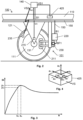
- Figure 3 shows a graph illustrating an example of how the kinetic friction coefficient ⁇ k may be expressed as a function of the wheel slippage s, which here is understood to designate a common term for a sliding or spinning motion of the wheel relative to the rail.
- the wheel slippage s is applicable to retardation as well as acceleration.
- the kinetic friction coefficient ⁇ k increases relatively proportionally with increasing wheel slippage s.
- the kinetic friction coefficient ⁇ k levels out somewhat.
- the friction coefficient peak value ⁇ e is associated with an optimal wheel slippage s e after which a further increase of wheel slippage s results in a gradually reduced kinetic friction coefficient ⁇ k .
- a parameter ⁇ m is determined that reflects the friction coefficient between the rail vehicle's 100 wheels the rails upon which the rail vehicle 100 travels.
- the peak value ⁇ e should be derived.
- the peak value ⁇ e may be derived as follows. When the absolute difference
- the peak value ⁇ e of the kinetic friction coefficient ⁇ k may be estimated relatively accurately.
- control unit 140 is configured to produce the control signals B1/A1, B2/A2, B3/A3 or B4/A4 such that an average brake/traction force applied to the at least one second wheel axle 132, 133 and 134 is gradually decreased when the brake/traction force applied to the first wheel axle 131 is gradually increased.
- the at least one second wheel axle 132, 133 and 134 compensate for the excessive force applied to the first wheel axle 131.
- this compensation is temporally matched.
- the control unit 140 is configured to produce the control signals B1/A1, B2/A2, B3/A3 and B4/A4 such that, at each point in time, the gradual decrease of the average brake/traction force applied to the at least one second wheel axle 132, 133 and 134 corresponds to the gradual increase of the brake/traction force applied to the first wheel axle 131. Namely, thereby the deviating brake/traction force applied to first wheel axle 131 is masked by the opposite deviation represented by the brake/traction force applied to the least one second wheel axle 132, 133 and 134.
- FIG. 2 shows a brake unit 101 according to one embodiment of the invention.
- the brake unit 101 is configured to receive the control signals, e.g. representing a brake command B1 from the control unit 140, for example via a data bus 150. In response thereto, the brake unit 101 is configured to execute a brake action.
- the brake unit 101 may contain a rotatable member 111, first and second pressing members, here symbolized by 211, a brake actuator 220, a gear assembly (not shown) and an electric motor 230.
- the rotatable member 111 which may be represented by a brake disc or a brake drum is mechanically linked to at least one wheel 121 of the rail vehicle 100.
- the brake actuator 220 is preferably configured to produce a brake force signal BF1 to the electric motor 230, which, in turn, causes the electric motor 230 to cause the first and second pressing members 211 to move relative to the rotatable member 111.
- the electric motor 230 may be replaced by a pneumatically operated piston-and-cylinder arrangement configured to actuate the first and second pressing members.
- the data bus 150 may, of course, be configured to transmit the all the control signals B1, A1; B2, A2; B3, A3; B4 and/or A4 from the control unit 140 to each brake/ traction unit in the set of brake/traction units 101, 161; 102, 162; 103, 163, 104 and/or 164.
- Each of the first and second pressing members 211 is configured to move relative to the rotatable member 111 to execute the brake action.
- the brake action involves applying a particular brake force on the rotatable member 111.
- the brake action may also involve reducing or releasing an already applied brake force.
- control unit 140 is configured to obtain a first wheel speed signal ⁇ 1 indicating a rotational speed of at least one first wheel 121 on a first wheel axle of the wheel axles to which first wheel axle a first traction unit 161 in the set of traction units is configured to apply a traction force.
- control unit 140 is configured to obtain a second wheel speed signal ⁇ a indicating an average rotational speed of at least one second wheel, say 122, 123 and 124, on at least one second wheel axle 132, 133 and 134 respectively of said wheel axles to which at least one second wheel axle 132, 133 and 134 at least one second traction unit 162, 163 and 164 respectively in the set of traction units is configured to apply a respective traction force.
- a second wheel speed signal ⁇ a indicating an average rotational speed of at least one second wheel, say 122, 123 and 124, on at least one second wheel axle 132, 133 and 134 respectively of said wheel axles to which at least one second wheel axle 132, 133 and 134 at least one second traction unit 162, 163 and 164 respectively in the set of traction units is configured to apply a respective traction force.
- control unit 140 is configured to produce a first control signal A1 to the first traction unit 161 such that this unit applies a gradually increasing traction force to the first wheel axle 131 until an absolute difference
- the control unit 140 is configured to determine the parameter ⁇ m reflecting the friction coefficient ⁇ e between the wheels 121, 122, 123 and 124 and a set of rails 181 and 182 respectively upon which the rail vehicle 100 travels.
- the control unit 140 may be configured to produce a first control signal A1 to the first traction unit 161 such that this unit applies a gradually increases the traction force applied to the first wheel axle 131.
- the control unit 140 is here configured to produce at least one second control signal B2, B3 and B4 such that these units apply gradually increasing brake forces to the at least one second wheel axle 132, 133 and 134 respectively.
- the control unit 140 is configured to continue to produce the first control signal A1 and the at least one second control signals B2, B3 and B4 until an absolute difference
- the control unit 140 is configured to determine the parameter ⁇ m reflecting the friction coefficient ⁇ e between the wheels 121, 122, 123 and 124 and a set of rails 181 and 182 respectively upon which the rail vehicle 100 travels. This determining is possible based on knowledge about the respective traction and brake forces applied to the wheel axles when the absolute difference
- control unit 140 instead produces the first control signal B1 to the first brake unit 101 such that this unit applies a gradually increasing brake force to the first wheel axle 131, and in parallel, the control unit 140 produces the at least one second control signal A2, A3 and A4 to the at least one second traction unit 162, 163 and 164 respectively such that these units apply gradually increasing traction forces to the at least one second wheel axle 132, 133 and 134.
- the friction testing system contains a set of rotational speed sensors 215, 235 and 425 configured to produce the first wheel speed signal ⁇ 1 and a respective wheel speed signal ⁇ 2 , ⁇ 3 and ⁇ 4 of the at least one second wheel 122, 123 and 124 on the at least one second wheel axle 132, 133 and 134 respectively.
- the rotational speed sensor may include a tachometer 215 that is arranged on or near the first wheel axle 131 and/or on or near the at least one second wheel axle 132, 133 and/or 134 respectively.
- FIG. 4 schematically illustrates an accelerometer 425 according to one embodiment of the invention.
- the friction testing system contains a first accelerometer 425 and at least one second accelerometer 235.
- the first accelerometer 425 is arranged in a frame element 110 of the rail vehicle 100.
- the first accelerometer 425 is configured to produce at least one primary vector signal VS1 representing an acceleration, of the a rail vehicle 100 in at least one dimension, typically in each of the three spatial directions a X , a Y and a Z and respective rotations a R , ap and a W around axes along each of these directions.
- Each of the at least one second accelerometer 235 is eccentrically arranged relative to a rotation axis of at least one wheel, say 121 as illustrated in Figure 2 of the rail vehicle 100.
- the at least one second accelerometer 235 is configured to produce at least one secondary vector signal VS2 expressing movements of the at least one second accelerometer 235 in a plane orthogonal to the rotation axis of the at least one wheel 121.
- control unit 140 is configured to obtain the first wheel speed signal ⁇ 1 and/or at least one of the second wheel speed signals ⁇ 2 , ⁇ 3 and/or ⁇ 4 based on the primary and secondary vector signals VS1 and VS2 respectively using mechanic calculations.
- the brake actuator 120 preferably includes processing circuitry and programmed memory units, the design of which will be briefly described below with reference to Figure 5 .
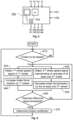
- FIG. 5 shows a block diagram of the control unit 140 according to one embodiment of the invention.
- the control unit 140 includes processing circuitry in the form of at least one processor 530 and a memory unit 520, i.e. non-volatile data carrier, storing a computer program 525, which, in turn, contains software for making the at least one processor 530 execute the actions mentioned in this disclosure when the computer program 525 is run on the at least one processor 530.
- the control unit 140 contains inputs configured to receive the wheel speed signals ⁇ 1 , ⁇ 2 , ⁇ 3 , and ⁇ 4 . Alternatively, or additionally, the control unit 140 may also contain inputs configured to receive the primary and secondary vector signals VS1 and VS2 respectively. Further, the control unit 140 contains outputs configured to provide the control signals B1, B2, B3 and B4 and/or A1, A2, A3 and A4. According to embodiments of the invention one or more of the above input and/or output signals may be communicated via the data bus 150.
- a first step 610 it is checked whether the friction is to be tested, for example in response to the expiry of a timer function, or in response to an operator command. If, in step 610 it is found that the friction shall be tested, steps 620 and 630 follow, which may or may not be executed in parallel. If, in step 610 it is found that the friction shall not be tested, the procedure loops back and stays in step 610.
- step 620 the control unit 140 obtains a first wheel speed signal ⁇ 1 indicating a rotational speed of at least one first wheel 121 on a first of said wheel axles 131 to which a first brake/traction unit 101/161 in the set of brake/traction units is configured to apply a brake/ traction force.
- step 630 the control unit 140 obtains a second wheel speed signal ⁇ a indicating an average rotational speed of at least one second wheel 122, 123 and/or 124 on at least one second of said wheel axles 132, 133 and/or 134 respectively to which at least one second brake/traction unit in the set of brake/traction units is configured to apply a respective brake/traction force.
- step 640 the control unit 140 produces a first control signal to the first brake/traction unit 101 or 161 respectively such that this unit applies a gradually increasing brake/traction force to the first wheel axle 131.
- control unit 140 produces at least one second control signal to the at least one second brake/traction unit 102, 103 and 104 or 162, 163 and 164 respectively such that these units apply gradually decreasing brake/traction forces to the at least one second wheel axle 132, 133 and 134 respectively.
- a step 660 follows after the steps 640 and 650, which step 660 checks if an absolute difference
- a parameter ⁇ m is determined, which reflects a friction coefficient ⁇ e between the wheels 121, 122, 123 and 124 and the set of rails 181 and 182 upon which the rail vehicle 100 travels. Thereafter, the procedure loops back to step 610.
- All of the process steps, as well as any sub-sequence of steps, described with reference to Figure 6 may be controlled by means of a programmed processor.
- the embodiments of the invention described above with reference to the drawings comprise processor and processes performed in at least one processor, the invention thus also extends to computer programs, particularly computer programs on or in a carrier, adapted for putting the invention into practice.
- the program may be in the form of source code, object code, a code intermediate source and object code such as in partially compiled form, or in any other form suitable for use in the implementation of the process according to the invention.
- the program may either be a part of an operating system, or be a separate application.
- the carrier may be any entity or device capable of carrying the program.
- the carrier may comprise a storage medium, such as a Flash memory, a ROM (Read Only Memory), for example a DVD (Digital Video/Versatile Disk), a CD (Compact Disc) or a semiconductor ROM, an EPROM (Erasable Programmable Read-Only Memory), an EEPROM (Electrically Erasable Programmable Read-Only Memory), or a magnetic recording medium, for example a floppy disc or hard disc.
- the carrier may be a transmissible carrier such as an electrical or optical signal which may be conveyed via electrical or optical cable or by radio or by other means.
- the carrier When the program is embodied in a signal, which may be conveyed, directly by a cable or other device or means, the carrier may be constituted by such cable or device or means.
- the carrier may be an integrated circuit in which the program is embedded, the integrated circuit being adapted for performing, or for use in the performance of, the relevant processes.
Landscapes
- Engineering & Computer Science (AREA)
- Transportation (AREA)
- Mechanical Engineering (AREA)
- Power Engineering (AREA)
- Regulating Braking Force (AREA)
- Electric Propulsion And Braking For Vehicles (AREA)
- Braking Arrangements (AREA)
- Train Traffic Observation, Control, And Security (AREA)
Priority Applications (8)
| Application Number | Priority Date | Filing Date | Title |
|---|---|---|---|
| EP22172518.7A EP4275985B1 (fr) | 2022-05-10 | 2022-05-10 | Système de test de friction, procédé de test de friction mis en oeuvre par ordinateur pour un véhicule ferroviaire, programme informatique et support de données non volatiles |
| KR1020247034162A KR20250006025A (ko) | 2022-05-10 | 2023-02-08 | 마찰 검사 시스템, 철도 차량용 컴퓨터 구현 마찰 검사 방법, 컴퓨터 프로그램 및 비휘발성 데이터 캐리어 |
| CA3247181A CA3247181A1 (fr) | 2022-05-10 | 2023-02-08 | Système de test de frottement, procédé de test de frottement mis en œuvre par ordinateur pour un véhicule ferroviaire, programme informatique et support de données non volatil |
| JP2024566375A JP2025516600A (ja) | 2022-05-10 | 2023-02-08 | 鉄道車両用摩擦試験システム、コンピュータ実装された鉄道車両用摩擦試験方法、コンピュータプログラム、および不揮発性データキャリア |
| US18/862,626 US12606219B2 (en) | 2022-05-10 | 2023-02-08 | Friction testing system, computer-implemented friction-testing method for a rail vehicle, computer program and non-volatile data carrier |
| CN202380035459.2A CN119053492A (zh) | 2022-05-10 | 2023-02-08 | 摩擦测试系统、轨道车辆的计算机实施摩擦测试方法、计算机程序和非易失性数据载体 |
| PCT/EP2023/053123 WO2023217421A1 (fr) | 2022-05-10 | 2023-02-08 | Système de test de frottement, procédé de test de frottement mis en œuvre par ordinateur pour un véhicule ferroviaire, programme informatique et support de données non volatil |
| MX2024013432A MX2024013432A (es) | 2022-05-10 | 2024-10-30 | Sistema de prueba de friccion, metodo de prueba de friccion implementado por computadora para un vehiculo ferroviario, programa informatico y portador de datos no volatil |
Applications Claiming Priority (1)
| Application Number | Priority Date | Filing Date | Title |
|---|---|---|---|
| EP22172518.7A EP4275985B1 (fr) | 2022-05-10 | 2022-05-10 | Système de test de friction, procédé de test de friction mis en oeuvre par ordinateur pour un véhicule ferroviaire, programme informatique et support de données non volatiles |
Publications (3)
| Publication Number | Publication Date |
|---|---|
| EP4275985A1 true EP4275985A1 (fr) | 2023-11-15 |
| EP4275985C0 EP4275985C0 (fr) | 2026-03-18 |
| EP4275985B1 EP4275985B1 (fr) | 2026-03-18 |
Family
ID=81603626
Family Applications (1)
| Application Number | Title | Priority Date | Filing Date |
|---|---|---|---|
| EP22172518.7A Active EP4275985B1 (fr) | 2022-05-10 | 2022-05-10 | Système de test de friction, procédé de test de friction mis en oeuvre par ordinateur pour un véhicule ferroviaire, programme informatique et support de données non volatiles |
Country Status (8)
| Country | Link |
|---|---|
| US (1) | US12606219B2 (fr) |
| EP (1) | EP4275985B1 (fr) |
| JP (1) | JP2025516600A (fr) |
| KR (1) | KR20250006025A (fr) |
| CN (1) | CN119053492A (fr) |
| CA (1) | CA3247181A1 (fr) |
| MX (1) | MX2024013432A (fr) |
| WO (1) | WO2023217421A1 (fr) |
Citations (5)
| Publication number | Priority date | Publication date | Assignee | Title |
|---|---|---|---|---|
| EP0078655A2 (fr) * | 1981-10-31 | 1983-05-11 | Westinghouse Brake And Signal Company Limited | Système de commande de dérapage de roue |
| US20050206230A1 (en) * | 2004-02-17 | 2005-09-22 | Railpower Technologies Corp. | Managing wheel slip in a locomotive |
| EP3483029A1 (fr) * | 2017-11-10 | 2019-05-15 | Siemens Aktiengesellschaft | Système et procédé pour tester des conditions d'adhérence sur une piste |
| DE102019204371A1 (de) * | 2019-03-28 | 2020-10-01 | Siemens Mobility GmbH | Verfahren zur automatischen Zugkontrolle mit Schlupferfassung |
| EP2918459B1 (fr) * | 2014-03-14 | 2021-01-20 | Bombardier Transportation GmbH | Procédé de détermination d'un coefficient d'adhérence entre une roue d'un véhicule ferroviaire et un rail |
Family Cites Families (5)
| Publication number | Priority date | Publication date | Assignee | Title |
|---|---|---|---|---|
| AT411283B (de) * | 2000-03-16 | 2003-11-25 | Knorr Bremse Gmbh | Steuerung der bewegung einer schiebe- bzw. schwenkschiebetür in ihrem schliessendbereich |
| US8738202B2 (en) * | 2010-11-18 | 2014-05-27 | Ztr Control Systems | Method and apparatus for controlling sanding on locomotives |
| DE102011110053A1 (de) * | 2011-08-12 | 2013-02-14 | Knorr-Bremse Systeme für Schienenfahrzeuge GmbH | Bremsanlage mit Magnetschienenbremseinrichtung |
| DE102011110050B4 (de) * | 2011-08-12 | 2014-03-06 | Knorr-Bremse Systeme für Schienenfahrzeuge GmbH | Bremsanlage mit Magnetschienenbremseinrichtung |
| US8874345B2 (en) * | 2012-04-04 | 2014-10-28 | General Electric Company | Method and system for identifying an erroneous speed of a vehicle |
-
2022
- 2022-05-10 EP EP22172518.7A patent/EP4275985B1/fr active Active
-
2023
- 2023-02-08 JP JP2024566375A patent/JP2025516600A/ja active Pending
- 2023-02-08 KR KR1020247034162A patent/KR20250006025A/ko active Pending
- 2023-02-08 CA CA3247181A patent/CA3247181A1/fr active Pending
- 2023-02-08 US US18/862,626 patent/US12606219B2/en active Active
- 2023-02-08 CN CN202380035459.2A patent/CN119053492A/zh active Pending
- 2023-02-08 WO PCT/EP2023/053123 patent/WO2023217421A1/fr not_active Ceased
-
2024
- 2024-10-30 MX MX2024013432A patent/MX2024013432A/es unknown
Patent Citations (5)
| Publication number | Priority date | Publication date | Assignee | Title |
|---|---|---|---|---|
| EP0078655A2 (fr) * | 1981-10-31 | 1983-05-11 | Westinghouse Brake And Signal Company Limited | Système de commande de dérapage de roue |
| US20050206230A1 (en) * | 2004-02-17 | 2005-09-22 | Railpower Technologies Corp. | Managing wheel slip in a locomotive |
| EP2918459B1 (fr) * | 2014-03-14 | 2021-01-20 | Bombardier Transportation GmbH | Procédé de détermination d'un coefficient d'adhérence entre une roue d'un véhicule ferroviaire et un rail |
| EP3483029A1 (fr) * | 2017-11-10 | 2019-05-15 | Siemens Aktiengesellschaft | Système et procédé pour tester des conditions d'adhérence sur une piste |
| DE102019204371A1 (de) * | 2019-03-28 | 2020-10-01 | Siemens Mobility GmbH | Verfahren zur automatischen Zugkontrolle mit Schlupferfassung |
Also Published As
| Publication number | Publication date |
|---|---|
| US12606219B2 (en) | 2026-04-21 |
| JP2025516600A (ja) | 2025-05-30 |
| MX2024013432A (es) | 2024-12-06 |
| WO2023217421A1 (fr) | 2023-11-16 |
| KR20250006025A (ko) | 2025-01-10 |
| EP4275985C0 (fr) | 2026-03-18 |
| CA3247181A1 (fr) | 2023-11-16 |
| EP4275985B1 (fr) | 2026-03-18 |
| US20250276723A1 (en) | 2025-09-04 |
| CN119053492A (zh) | 2024-11-29 |
Similar Documents
| Publication | Publication Date | Title |
|---|---|---|
| CN110997429B (zh) | 确定轨道车辆纵向动态行为变化的方法和装置 | |
| KR102096148B1 (ko) | 자동차 전기식 주차 브레이크 시스템을 위한 주차 브레이크 작동 방법 | |
| US12570250B2 (en) | Method for determining an optimum or maximum-permissible speed of a rail vehicle | |
| US20180163804A1 (en) | Method and System for Analyzing the Wear Behavior of Brake Pads / Linings | |
| EP4275985A1 (fr) | Système de test de friction, procédé de test de friction mis en oeuvre par ordinateur pour un véhicule ferroviaire, programme informatique et support de données non volatiles | |
| US12221087B2 (en) | Determination of a possible deceleration variable | |
| EP3847065B1 (fr) | Procédé de détection de dysfonctionnements d'un appareil de freinage électro-actionné d'un véhicule automobile | |
| CN112848920B (zh) | 电动汽车的泊车方法、装置及车辆 | |
| US11926329B2 (en) | Motor vehicle control module and method, comprising an evaluation of rear wheel speed based on the front wheels only | |
| US10227012B2 (en) | Brake control device of railcar | |
| JP7339351B2 (ja) | 鉄道車両の制動動作の検出方法及び鉄道車両の緊急制動方法 | |
| WO2024052143A1 (fr) | Ensemble frein à commande électrique, procédé mis en œuvre par ordinateur pour commander un ensemble frein à commande électrique, programme informatique et support de données non volatil | |
| EP4556330A1 (fr) | Véhicule ferroviaire, contrôleur pour unités de freinage à commande électrique, procédé mis en uvre par ordinateur associé, programme informatique et support de données non volatil | |
| US9132814B2 (en) | Systems and methods for vibration mitigation in a vehicle | |
| EP4303088B1 (fr) | Contrôleur pour estimer les poids individuels des essieux d'un véhicule ferroviaire, procédé mis en oeuvre par ordinateur correspondant, programme informatique et support de données non volatiles | |
| JP3636894B2 (ja) | 電気ブレーキの制御方法及びその装置 | |
| JP2000013903A (ja) | 電気ブレーキの制御方法及びその装置 | |
| EP4306384B1 (fr) | Système de communication des données, procédé mis en oeuvre par ordinateur destiné à la communication des données dans un réseau ferroviaire, programme informatique et support de données non volatiles | |
| CN119421820A (zh) | 用于确定运动估计值的估计装置和方法 | |
| CN116669997A (zh) | 改善的机电制动器的夹紧力矩的控制方法 | |
| CN111252053A (zh) | 用于操作具有电动制动力分配器的机动车辆的方法 |
Legal Events
| Date | Code | Title | Description |
|---|---|---|---|
| PUAI | Public reference made under article 153(3) epc to a published international application that has entered the european phase |
Free format text: ORIGINAL CODE: 0009012 |
|
| STAA | Information on the status of an ep patent application or granted ep patent |
Free format text: STATUS: THE APPLICATION HAS BEEN PUBLISHED |
|
| AK | Designated contracting states |
Kind code of ref document: A1 Designated state(s): AL AT BE BG CH CY CZ DE DK EE ES FI FR GB GR HR HU IE IS IT LI LT LU LV MC MK MT NL NO PL PT RO RS SE SI SK SM TR |
|
| STAA | Information on the status of an ep patent application or granted ep patent |
Free format text: STATUS: REQUEST FOR EXAMINATION WAS MADE |
|
| 17P | Request for examination filed |
Effective date: 20240322 |
|
| RBV | Designated contracting states (corrected) |
Designated state(s): AL AT BE BG CH CY CZ DE DK EE ES FI FR GB GR HR HU IE IS IT LI LT LU LV MC MK MT NL NO PL PT RO RS SE SI SK SM TR |
|
| GRAP | Despatch of communication of intention to grant a patent |
Free format text: ORIGINAL CODE: EPIDOSNIGR1 |
|
| STAA | Information on the status of an ep patent application or granted ep patent |
Free format text: STATUS: GRANT OF PATENT IS INTENDED |
|
| GRAS | Grant fee paid |
Free format text: ORIGINAL CODE: EPIDOSNIGR3 |
|
| INTG | Intention to grant announced |
Effective date: 20260109 |
|
| GRAA | (expected) grant |
Free format text: ORIGINAL CODE: 0009210 |
|
| STAA | Information on the status of an ep patent application or granted ep patent |
Free format text: STATUS: THE PATENT HAS BEEN GRANTED |
|
| AK | Designated contracting states |
Kind code of ref document: B1 Designated state(s): AL AT BE BG CH CY CZ DE DK EE ES FI FR GB GR HR HU IE IS IT LI LT LU LV MC MK MT NL NO PL PT RO RS SE SI SK SM TR |
|
| REG | Reference to a national code |
Ref country code: CH Ref legal event code: F10 Free format text: ST27 STATUS EVENT CODE: U-0-0-F10-F00 (AS PROVIDED BY THE NATIONAL OFFICE) Effective date: 20260318 Ref country code: GB Ref legal event code: FG4D |
|
| REG | Reference to a national code |
Ref country code: IE Ref legal event code: FG4D |