EP4276242A1 - Améliorations apportées au profil de rail ferroviaire - Google Patents
Améliorations apportées au profil de rail ferroviaire Download PDFInfo
- Publication number
- EP4276242A1 EP4276242A1 EP22844620.9A EP22844620A EP4276242A1 EP 4276242 A1 EP4276242 A1 EP 4276242A1 EP 22844620 A EP22844620 A EP 22844620A EP 4276242 A1 EP4276242 A1 EP 4276242A1
- Authority
- EP
- European Patent Office
- Prior art keywords
- rail
- web
- triple
- rails
- walls
- Prior art date
- Legal status (The legal status is an assumption and is not a legal conclusion. Google has not performed a legal analysis and makes no representation as to the accuracy of the status listed.)
- Granted
Links
Images


Classifications
-
- E—FIXED CONSTRUCTIONS
- E01—CONSTRUCTION OF ROADS, RAILWAYS, OR BRIDGES
- E01B—PERMANENT WAY; PERMANENT-WAY TOOLS; MACHINES FOR MAKING RAILWAYS OF ALL KINDS
- E01B5/00—Rails; Guard rails; Distance-keeping means for them
- E01B5/02—Rails
-
- E—FIXED CONSTRUCTIONS
- E01—CONSTRUCTION OF ROADS, RAILWAYS, OR BRIDGES
- E01B—PERMANENT WAY; PERMANENT-WAY TOOLS; MACHINES FOR MAKING RAILWAYS OF ALL KINDS
- E01B5/00—Rails; Guard rails; Distance-keeping means for them
- E01B5/18—Guard rails; Connecting, fastening or adjusting means therefor
Definitions
- the present invention relates to improvements in railroad rail profile of the type laid and fixed on ties for track rolling surface composition, where, notably, said profile includes technical innovations that include a triple or double web conformation in order to improve the stability of the rail and, consequently, the performance of the vehicles for the rail transport, as well as, provides holes in said webs that allow the crossing of diverse wirings or cables.
- rail transport is the form of land transport with the highest cargo capacity, transporting people or diverse cargo such as bulk cargo, minerals, agricultural products, animal products, unified goods, ferrous materials, liquid bulk cargo such as oil, gasoline, liquid nitrogen, among others.
- railroad rails comprise steel bars or beams whose basic profile is 'Vignole' type consisting of foot, web and head as defined by NBR 7590 and NBR 7650.
- NBR 7650 defines head as the part of the rail intended for the support and displacement of the railroad wheel and web as the part of the rail between the head and the foot, which, in turn, is defined as the base of the rail constituted by the longest mass of the double 'T', through which the rail is supported and fixed to the ties.
- Another limitation lies in the environmental impact generated by the constant change of railroad rail profiles damaged by excess weight of loads, generating a higher cost and excessive expenditure of natural resources over time.
- the current state of the art has documents referring to the railroad rail profile, such as the document PI 9406964-6, which addresses to a rail for use on a railroad that has a section, a head having a transport surface of traffic and a base, wherein the head comprises a traffic transport surface that is composed of low carbon martensite.
- Document CN 102330390 refers to a railroad rail that presents a shock-absorbing layer, ties, blocking walls and combined rails, in which there is a part of rail sleeves and a rail beam, and the rail is firmly connected to the rail rising beam.
- Document CN 202595583 comprises a guide rail for continuous casting rails that aims at improving the lubricating property between the guide rail and the rollers to reduce abrasion
- said rail includes a left side wall and a right side wall, and grooves to contain lubricant are arranged in positions, which are contacted with the rollers, of the left side wall and the right side wall, as the grooves are arranged in the surfaces, which are contacted with the rollers, of the guide rail, and the grooves are filled with the lubricant, the loss caused by rolling friction is reduced and the life of the guide rail and rollers is extended.
- Document CN 2292829 discloses a new form of train rail in which it comprises not only the rail, but a set of components directly coupled to the rail, a support and a structure coupled below said support that need to be associated so that the proposed invention works, as can be seen in figure 1 of said application.
- the present invention comprises a train rail with a double or triple web, which is applied on ties similarly to the conventional rail, not requiring any additional components installed under the tie.
- the geometry of the rail (6) disclosed in the Chinese document is different from that disclosed in the present application.
- the prior art is not able to provide the same advantages proposed by the present invention.
- Document CN 2789309 describes a kind of rail support consisting of two components that are fixed along the web of the rail to reduce the vibration of the rail generated by the train. When applied to the rail, the support is positioned along the web so that the support does not touch the ground.
- the invention proposed in the Chinese document does not suggest a new form of rail with double or triple web capable of offering greater stability to the rail when subjected to loading.
- Document US 500688 describes a plurality of train rails with purposes that comprise from rails that keep the head at the same height of the surface on which it is installed, rails with double heads to rails with lateral supports to avoid bending the web. Therefore, the matter disclosed in that document does not suggest or envision a rail with a double or triple web, installed in the same way as conventional rails and wherein they aim at increasing the strength of the rail using a smaller amount of material and provide greater stability to the rail. Furthermore, considering the filing date of document US 500688 , it would not be possible to envision the same technical problem as the focus of the present application.
- the present invention comprises a profile for the composition of a railroad rail with provision for at least one pair of webs in each rail profile, in addition to being able to be provided with a set of cutouts of a plurality of geometric shapes that allow the crossing of wires and cables for diverse purposes.
- the webs arranged more laterally to the center of the rail provide greater stability to the rail.
- the plurality of holes enables greater capacity to absorb stresses and vibrations, consequently, greater stability for the train, especially at high speeds, in addition to serving as a mooring point for transporting the rails.
- the adopted geometries also present a greater mechanical strength in relation to the common rail profiles compared to the same amount of used material.
- the present invention comprises a railroad rail profile (10) of the type for laying and fixing on ties (not illustrated) for track rolling surface composition.
- Said profile (10) is made of steel or other similar material and consists of a foot (11), a web (12) and a head (13).
- the profile (10) provides in a first embodiment that the web (12) is formed by two parallel walls (12a) with thicknesses W 1 and W 2 , and in a second embodiment, in which the profile (10) presents an arrangement of a central wall (12b) with thickness W 2 and two walls (12a) with thicknesses W 1 and W 3 , forming a rail with a triple web (12).
- the profile (10), in the form of a double or triple web, has a spacing (x) between the walls (12a) in the range of 4 to 45 mm.
- the webs (12) have a thickness (w1, w2 or w3) in the range of 13 to 18 mm, being preferably 9.71 mm for double web rails and 8 mm for triple web rails.
- the webs of the double or triple rails still have different thicknesses in the same section of said rail. This variation is interesting in curved sections, where the train loads on the rails change substantially.
- the webs (12) can have uniform dimensions, that is, equal dimensions for the walls (12a) in the double web rails or the same dimensions for the walls (12a) and central wall (12c) in the triple web rails, or variable dimensions between the walls (12a) in the double web rails or between the walls (12a) and/or central wall (12c) in the triple web rails, in order to adapt the rail for different loads, such as in curved sections.
- the lower ends of the walls (12a) of the triple web have side branches (11a), directed in directions opposite each other, comprising the foot (11), while the upper ends of said walls (12a) are joined together by a single sector comprising the head (13).
- the walls (12a) and (12b) can receive holes or cutouts (14) of varied geometries and aligned with each other according to the crossing axis (E1), preferably located in the center of said walls, allowing the passage of wires/cables (Cb), as well as configuring mechanical means of absorption of stresses and vibrations.
- Said cutouts (14) can present varied dimensions, in the range from AAto BB, and different shapes such as circular, oblong/oval and rectangular with rounded edges, as well as being both concentric and eccentric, wherein the cutouts (14) are preferably concentric, circular or ellipsoidal.
- the present invention proposes railroad rail embodiments that are more resistant and have the same linear weight of a conventional rail.
- the TR68 rail is a rail with an approximate linear weight of 68 kg/m with a height of about 185.74 mm, width of the foot (11), head (13) and web (12) of 152.4 mm, 74 mm and 17.46 mm, respectively.
- the profiles (10) evaluated are double web and triple web ones, maintaining the same dimensions of the head and foot of the TR68 rail, with a height of 159.54 mm and distance between the external surfaces of the walls (12a) of 35.42 mm, distance X of 8 mm for double web and 16 mm for triple web, thickness W 1 and W 2 of 13.71 mm for double web and W 1 and W 3 of 9.71 mm for the walls (12a) and W 3 of 8 mm for the central wall (12b) of the triple web rail.
- the spacing between ties is a variable that depends on several factors and that, in this comparison, should be considered as a fixed dimension. It is calculated as a function of the allowable stress on the ballast, the tamping area, the increased wheel load and the impact coefficient. In addition, it also depends on the type of material that the tie is made of (wood, concrete, steel, etc.) and on the gauge, as shown in Table 1. In this way, the spacing adopted is 0.70 m because it is the largest spacing that will cause the greatest stresses and strains in the rail. Table 1 - Tie spacing.
- the dimensioning of the rail was carried out using the "simplified" Talbot method, considering the inelastic supports with a spacing of 0.70 m, regardless of the distances between the axles of the cars (the most used in Brazil are 1575 mm, 1727 mm and 1828 mm).
- the value of the load applied to the rail was defined based on the largest loads used in Brazilian railroads, which is 32 ton/axle. In addition, a safety factor of 2.5 was applied, resulting in a load of 40 ton on each rail.
- the rail was modeled based on the dimensions provided in NBR 7590:2012 and the length of the modeled rail was determined based on the size and spacing of the ties. As a boundary condition, the model was truncated and crimped at the ends and supported in the contact with the ties. The load application region corresponds to the contact between the train wheel and the rail.
- the computational mesh used in the analysis was constituted with elements of approximately 5 mm along the entire body and 1 mm in the regions demanding greater refinement (region of the double and triple rails slots).
- the total number of elements varies according to the analyzed profile.
- Table 2 presents the information of the used mesh.
- Profile Element type Total number of elements Total number of nodes TR68 Tetrahedron 70529 114295 Double rail Tetrahedron 102448 165754 Triple rail Tetrahedron 127346 208538
- the vertical load comes from the weight of the train when the train passes over the rail and the weight of the rail itself (gravitational field), causing a deflection in the vertical direction.
- the horizontal load is present in the system when the train makes a turn on the rails.
- the analyzes carried out take into account only the static loads on the structure.
- Figure 10 and Figure 11 present, respectively, the distribution of stresses and displacements in the cross section of the rail at the point of application of the load. There can be seen a change in the distribution of stresses and displacements, although with few significant differences between the profiles.
- Table 3 presents the comparisons of the maximum displacements. Table 3 - Comparisons of the maximum displacements. Profile Maximum displacement (mm) Variation (%) TR68 0.553 - Double Rail 0.671 121.34 Triple Rail 0.746 134.90
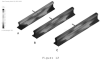
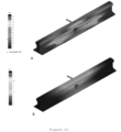
- Figure 13 shows the stress distribution in the simulated profiles. It is observed that the double rail and the triple rail generated a reduction of the maximum stresses of the rail. Likewise, Figure 14 shows a reduction in the displacement of the double and triple profile rails. Compared with the TR68 rail, the displacement presented in the double and triple rails were, respectively, 64.33% and 68.94% as shown in Table 4. Table 4 - Comparisons of the maximum displacements Profile Maximum displacement (mm) Variation (%) TR68 6.24 - Double Rail 3.77 60.42 Triple Rail 4.04 64.74
- Double and triple profile rails with 1 ⁇ 4" (6.35 mm) and 1 ⁇ 2" (12.7 mm) diameter holes were simulated for the passage of power and data cables. The same horizontal and vertical loads as in the previous cases were applied.
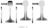
- Figure 16 through Figure 19 show the stress and displacement results for the 1 ⁇ 2" (12.7 mm) hole triple rail subjected to a horizontal load. Comparing with the results of the trail without the hole, there were no significant changes in the maximum values obtained. The same analysis can be observed for cases with a 1 ⁇ 4" (6.35 mm) hole.
- Figure 18 presents the stress and displacement results for the triple rail with a 1 ⁇ 2" (12.7 mm) hole subjected to a vertical load. Also, no changes were observed in stresses and displacements for both the 1 ⁇ 4" (6.35 mm) and 1 ⁇ 2" (12.7 mm) holes. It is observed that the insertion of punctual holes in the rails does not affect the global behavior of the system.
- the simulation presented a comparative analysis of three train rails subjected to vertical and horizontal loading, where the maximum stresses and maximum displacements of the rails were comparatively evaluated.
- both the double rail and the triple rail present a stress reduction of approximately 22% and displacement reduction of approximately 32% when subjected to a horizontal load.
- the rails showed similar behavior.
- Table 5 shows the dimension values of the different models of Vignole rails compared to the dimensions of a version of the double and triple web rails.
- UIC 60 72.00 16.50 150.00 172.00 60.21 76.70 GB 60 73.00 16.50 150.00 176.00 60.64 77.47 TR 68 74.61 17.46 152.40 185.73 67.41 86.52 DOUBLE WEB 74.61 X 8.00 152.40 159
Landscapes
- Engineering & Computer Science (AREA)
- Mechanical Engineering (AREA)
- Architecture (AREA)
- Civil Engineering (AREA)
- Structural Engineering (AREA)
- Train Traffic Observation, Control, And Security (AREA)
- Railway Tracks (AREA)
Priority Applications (1)
| Application Number | Priority Date | Filing Date | Title |
|---|---|---|---|
| HUE22844620A HUE072066T2 (hu) | 2022-03-24 | 2022-03-24 | Vasúti sínszál |
Applications Claiming Priority (1)
| Application Number | Priority Date | Filing Date | Title |
|---|---|---|---|
| PCT/BR2022/050105 WO2023178393A1 (fr) | 2022-03-24 | 2022-03-24 | Améliorations apportées au profil de rail ferroviaire |
Publications (4)
| Publication Number | Publication Date |
|---|---|
| EP4276242A4 EP4276242A4 (fr) | 2023-11-15 |
| EP4276242A1 true EP4276242A1 (fr) | 2023-11-15 |
| EP4276242C0 EP4276242C0 (fr) | 2025-02-26 |
| EP4276242B1 EP4276242B1 (fr) | 2025-02-26 |
Family
ID=88099412
Family Applications (1)
| Application Number | Title | Priority Date | Filing Date |
|---|---|---|---|
| EP22844620.9A Active EP4276242B1 (fr) | 2022-03-24 | 2022-03-24 | Profil de rail ferroviaire |
Country Status (10)
| Country | Link |
|---|---|
| US (1) | US20240183113A1 (fr) |
| EP (1) | EP4276242B1 (fr) |
| JP (1) | JP2025509056A (fr) |
| KR (1) | KR20240163643A (fr) |
| CN (1) | CN118434938A (fr) |
| CA (1) | CA3237878A1 (fr) |
| ES (1) | ES3031409T3 (fr) |
| HU (1) | HUE072066T2 (fr) |
| PL (1) | PL4276242T3 (fr) |
| WO (1) | WO2023178393A1 (fr) |
Family Cites Families (28)
| Publication number | Priority date | Publication date | Assignee | Title |
|---|---|---|---|---|
| US469392A (en) | 1892-02-23 | Street railway or tramway | ||
| US500688A (en) | 1893-07-04 | Ernest r | ||
| US477690A (en) * | 1892-06-28 | Railroad-rail and process of making the same | ||
| US531290A (en) * | 1894-12-18 | Railroad-rail | ||
| US918640A (en) | 1906-02-15 | 1909-04-20 | Campbell Allison | Sectional railway-rail. |
| US871232A (en) | 1907-03-14 | 1907-11-19 | Edwin K Morse | Railway-track construction. |
| US1173596A (en) * | 1915-10-05 | 1916-02-29 | George B Maltby | Track construction. |
| SU35205A1 (ru) * | 1932-05-19 | 1934-03-31 | А.А. Гринев | Пустотелый рельс |
| GB868598A (en) * | 1957-11-04 | 1961-05-17 | Jules Louis Charles Andrianne | Railway rail |
| JPS5347563B1 (fr) * | 1970-02-26 | 1978-12-22 | ||
| JPS51100407U (fr) * | 1975-02-12 | 1976-08-12 | ||
| JPS52136303U (fr) * | 1976-04-12 | 1977-10-17 | ||
| DE2900436A1 (de) * | 1979-01-08 | 1980-07-17 | Werner Prof Dr Ing Herbst | Eisenbahnschiene |
| US4801083A (en) * | 1987-03-06 | 1989-01-31 | Arteaga Alfredo G | Compound railroad track |
| JP2965280B2 (ja) * | 1992-12-16 | 1999-10-18 | 大和工業株式会社 | クロッシング用ノーズレールとその製造方法及び溶接クロッシングの製造方法 |
| US5526755A (en) * | 1995-08-25 | 1996-06-18 | Dalrymple; James G. | High adhesion magnetic rail |
| CN2292829Y (zh) | 1995-09-09 | 1998-09-30 | 徐继先 | 拱式轨路 |
| DE19911467A1 (de) | 1999-03-15 | 2000-09-21 | Knape Vermoegensverwaltungs Gm | Gleiskonstruktion mit gedämmter/elastischer Lagerung von Schienen an einer um Dämm-Material/Elastikmaterial herum geformten Stützschicht |
| JP3789065B2 (ja) * | 1999-11-16 | 2006-06-21 | 財団法人鉄道総合技術研究所 | 鉄道用レールおよび鉄道用軌道 |
| EP1524365A1 (fr) * | 2003-10-17 | 2005-04-20 | Nederlandse Organisatie voor toegepast-natuurwetenschappelijk Onderzoek TNO | Rail d'une voie ferrée à faible émission sonore |
| CN2789309Y (zh) | 2005-03-30 | 2006-06-21 | 陈羽庭 | 新型铁轨 |
| EP2390411A1 (fr) * | 2010-05-25 | 2011-11-30 | 3M Innovative Properties Company | Rail à faible bruit et son procédé de fabrication |
| CN102330390A (zh) | 2010-07-12 | 2012-01-25 | 严宏生 | 新型铁道 |
| EP2497581B1 (fr) * | 2011-03-11 | 2022-09-21 | Steel-Invest Ltd | Rail-poutre en acier pour un train magnétique, et méthode et système de fabrication d'un tel rail-poutre |
| CN202595583U (zh) | 2011-12-20 | 2012-12-12 | 西安奥奈特固体润滑工程学研究有限公司 | 一种连铸轨道用的导轨 |
| CN104005309B (zh) * | 2014-05-10 | 2015-11-04 | 青岛科而泰环境控制技术有限公司 | 剪切式轨道减振降噪装置 |
| EP3219851B1 (fr) * | 2014-11-11 | 2023-06-14 | Braskem S.A. | Poutre ferroviaire et procédé de fabrication d'une traverse ferroviaire |
| CN208328563U (zh) * | 2018-03-30 | 2019-01-04 | 广州铁路职业技术学院(广州铁路机械学校) | 一种减震消声钢轨 |
-
2022
- 2022-03-24 JP JP2024546035A patent/JP2025509056A/ja active Pending
- 2022-03-24 WO PCT/BR2022/050105 patent/WO2023178393A1/fr not_active Ceased
- 2022-03-24 US US17/760,244 patent/US20240183113A1/en active Pending
- 2022-03-24 ES ES22844620T patent/ES3031409T3/es active Active
- 2022-03-24 CN CN202280083387.4A patent/CN118434938A/zh active Pending
- 2022-03-24 PL PL22844620.9T patent/PL4276242T3/pl unknown
- 2022-03-24 HU HUE22844620A patent/HUE072066T2/hu unknown
- 2022-03-24 CA CA3237878A patent/CA3237878A1/fr active Pending
- 2022-03-24 KR KR1020247031627A patent/KR20240163643A/ko active Pending
- 2022-03-24 EP EP22844620.9A patent/EP4276242B1/fr active Active
Also Published As
| Publication number | Publication date |
|---|---|
| KR20240163643A (ko) | 2024-11-19 |
| EP4276242C0 (fr) | 2025-02-26 |
| CA3237878A1 (fr) | 2023-09-28 |
| JP2025509056A (ja) | 2025-04-11 |
| EP4276242B1 (fr) | 2025-02-26 |
| CN118434938A (zh) | 2024-08-02 |
| HUE072066T2 (hu) | 2025-10-28 |
| US20240183113A1 (en) | 2024-06-06 |
| PL4276242T3 (pl) | 2025-09-01 |
| WO2023178393A1 (fr) | 2023-09-28 |
| ES3031409T3 (en) | 2025-07-08 |
| BR112022016951A2 (pt) | 2023-11-21 |
Similar Documents
| Publication | Publication Date | Title |
|---|---|---|
| Kosenko et al. | Design of track structure for corridors of heavy-train traffic | |
| CN101699449B (zh) | 纵横垂向耦合的高速铁路高架车站上无缝道岔的设计方法 | |
| CN107761482B (zh) | 一种适于地铁车辆段库内线的弹性滑槽式减振扣件 | |
| US8556217B1 (en) | Elevated frog and rail crossing track assembly | |
| EP4276242A1 (fr) | Améliorations apportées au profil de rail ferroviaire | |
| AU2004202641B8 (en) | Multi-purpose Universal Sideframe for Railway Trucks | |
| US3383043A (en) | Railroad track structure | |
| CN101255673A (zh) | 双轨头钢轨及其构成的双轨轨道 | |
| US3147714A (en) | Elevated track and structure for supporting a coach for movement therealong | |
| CN210684340U (zh) | 一种可用于齿轨线路的y字型钢轨枕 | |
| Klauder Jr et al. | Improved spiral geometry for high-speed rail and predicted vehicle response | |
| HK40112681A (zh) | 铁路铁轨型材的改进 | |
| CN221049690U (zh) | 减振装置及轨道交通转向架 | |
| BR112022016951B1 (pt) | Aperfeiçoamentos em perfil de trilho ferroviário | |
| KR102174314B1 (ko) | 복합궤용 레일 설치 구조 | |
| CN104975542A (zh) | 固定型辙叉车轮传动区翼轨缓冲结构 | |
| CN203126870U (zh) | 一种铁路货车及其转向架、连接座 | |
| Bhatti et al. | Dynamic interaction between freight train and steel bridge | |
| RU2504611C2 (ru) | Железобетонная шпала | |
| CN105539479A (zh) | 磁浮列车的底架结构 | |
| CN216947670U (zh) | 一种地铁盾构下穿铁路轨道的加固结构 | |
| CN2474565Y (zh) | 一种变形夹板 | |
| RU2382130C2 (ru) | Железная дорога с односторонним движением и способ ее эксплуатации | |
| KR100696981B1 (ko) | 틸팅차량용 차륜 답면 | |
| CN224031381U (zh) | 一种可动心轨辙叉 |
Legal Events
| Date | Code | Title | Description |
|---|---|---|---|
| STAA | Information on the status of an ep patent application or granted ep patent |
Free format text: STATUS: UNKNOWN |
|
| STAA | Information on the status of an ep patent application or granted ep patent |
Free format text: STATUS: THE INTERNATIONAL PUBLICATION HAS BEEN MADE |
|
| PUAI | Public reference made under article 153(3) epc to a published international application that has entered the european phase |
Free format text: ORIGINAL CODE: 0009012 |
|
| STAA | Information on the status of an ep patent application or granted ep patent |
Free format text: STATUS: REQUEST FOR EXAMINATION WAS MADE |
|
| 17P | Request for examination filed |
Effective date: 20230127 |
|
| A4 | Supplementary search report drawn up and despatched |
Effective date: 20230914 |
|
| AK | Designated contracting states |
Kind code of ref document: A1 Designated state(s): AL AT BE BG CH CY CZ DE DK EE ES FI FR GB GR HR HU IE IS IT LI LT LU LV MC MK MT NL NO PL PT RO RS SE SI SK SM TR |
|
| STAA | Information on the status of an ep patent application or granted ep patent |
Free format text: STATUS: EXAMINATION IS IN PROGRESS |
|
| 17Q | First examination report despatched |
Effective date: 20240510 |
|
| GRAP | Despatch of communication of intention to grant a patent |
Free format text: ORIGINAL CODE: EPIDOSNIGR1 |
|
| STAA | Information on the status of an ep patent application or granted ep patent |
Free format text: STATUS: GRANT OF PATENT IS INTENDED |
|
| DAV | Request for validation of the european patent (deleted) | ||
| DAX | Request for extension of the european patent (deleted) | ||
| INTG | Intention to grant announced |
Effective date: 20240926 |
|
| GRAS | Grant fee paid |
Free format text: ORIGINAL CODE: EPIDOSNIGR3 |
|
| GRAA | (expected) grant |
Free format text: ORIGINAL CODE: 0009210 |
|
| STAA | Information on the status of an ep patent application or granted ep patent |
Free format text: STATUS: THE PATENT HAS BEEN GRANTED |
|
| AK | Designated contracting states |
Kind code of ref document: B1 Designated state(s): AL AT BE BG CH CY CZ DE DK EE ES FI FR GB GR HR HU IE IS IT LI LT LU LV MC MK MT NL NO PL PT RO RS SE SI SK SM TR |
|
| REG | Reference to a national code |
Ref country code: GB Ref legal event code: FG4D |
|
| REG | Reference to a national code |
Ref country code: CH Ref legal event code: EP |
|
| REG | Reference to a national code |
Ref country code: DE Ref legal event code: R096 Ref document number: 602022011254 Country of ref document: DE |
|
| REG | Reference to a national code |
Ref country code: IE Ref legal event code: FG4D |
|
| U01 | Request for unitary effect filed |
Effective date: 20250319 |
|
| U07 | Unitary effect registered |
Designated state(s): AT BE BG DE DK EE FI FR IT LT LU LV MT NL PT RO SE SI Effective date: 20250324 |
|
| PGFP | Annual fee paid to national office [announced via postgrant information from national office to epo] |
Ref country code: AT Payment date: 20250417 Year of fee payment: 4 |
|
| U20 | Renewal fee for the european patent with unitary effect paid |
Year of fee payment: 4 Effective date: 20250324 |
|
| PG25 | Lapsed in a contracting state [announced via postgrant information from national office to epo] |
Ref country code: RS Free format text: LAPSE BECAUSE OF FAILURE TO SUBMIT A TRANSLATION OF THE DESCRIPTION OR TO PAY THE FEE WITHIN THE PRESCRIBED TIME-LIMIT Effective date: 20250526 |
|
| REG | Reference to a national code |
Ref country code: ES Ref legal event code: FG2A Ref document number: 3031409 Country of ref document: ES Kind code of ref document: T3 Effective date: 20250708 |
|
| PGFP | Annual fee paid to national office [announced via postgrant information from national office to epo] |
Ref country code: ES Payment date: 20250519 Year of fee payment: 4 |
|
| PG25 | Lapsed in a contracting state [announced via postgrant information from national office to epo] |
Ref country code: IS Free format text: LAPSE BECAUSE OF FAILURE TO SUBMIT A TRANSLATION OF THE DESCRIPTION OR TO PAY THE FEE WITHIN THE PRESCRIBED TIME-LIMIT Effective date: 20250626 |
|
| PG25 | Lapsed in a contracting state [announced via postgrant information from national office to epo] |
Ref country code: HR Free format text: LAPSE BECAUSE OF FAILURE TO SUBMIT A TRANSLATION OF THE DESCRIPTION OR TO PAY THE FEE WITHIN THE PRESCRIBED TIME-LIMIT Effective date: 20250226 |
|
| PG25 | Lapsed in a contracting state [announced via postgrant information from national office to epo] |
Ref country code: GR Free format text: LAPSE BECAUSE OF FAILURE TO SUBMIT A TRANSLATION OF THE DESCRIPTION OR TO PAY THE FEE WITHIN THE PRESCRIBED TIME-LIMIT Effective date: 20250527 |
|
| PGFP | Annual fee paid to national office [announced via postgrant information from national office to epo] |
Ref country code: CH Payment date: 20250619 Year of fee payment: 4 |
|
| PG25 | Lapsed in a contracting state [announced via postgrant information from national office to epo] |
Ref country code: SM Free format text: LAPSE BECAUSE OF FAILURE TO SUBMIT A TRANSLATION OF THE DESCRIPTION OR TO PAY THE FEE WITHIN THE PRESCRIBED TIME-LIMIT Effective date: 20250226 |
|
| PG25 | Lapsed in a contracting state [announced via postgrant information from national office to epo] |
Ref country code: SK Free format text: LAPSE BECAUSE OF FAILURE TO SUBMIT A TRANSLATION OF THE DESCRIPTION OR TO PAY THE FEE WITHIN THE PRESCRIBED TIME-LIMIT Effective date: 20250226 |
|
| REG | Reference to a national code |
Ref country code: HU Ref legal event code: AG4A Ref document number: E072066 Country of ref document: HU |
|
| PG25 | Lapsed in a contracting state [announced via postgrant information from national office to epo] |
Ref country code: MC Free format text: LAPSE BECAUSE OF FAILURE TO SUBMIT A TRANSLATION OF THE DESCRIPTION OR TO PAY THE FEE WITHIN THE PRESCRIBED TIME-LIMIT Effective date: 20250226 |
|
| PLBE | No opposition filed within time limit |
Free format text: ORIGINAL CODE: 0009261 |
|
| STAA | Information on the status of an ep patent application or granted ep patent |
Free format text: STATUS: NO OPPOSITION FILED WITHIN TIME LIMIT |
|
| REG | Reference to a national code |
Ref country code: CH Ref legal event code: L10 Free format text: ST27 STATUS EVENT CODE: U-0-0-L10-L00 (AS PROVIDED BY THE NATIONAL OFFICE) Effective date: 20260107 |
|
| PG25 | Lapsed in a contracting state [announced via postgrant information from national office to epo] |
Ref country code: IE Free format text: LAPSE BECAUSE OF NON-PAYMENT OF DUE FEES Effective date: 20250324 |
|
| 26N | No opposition filed |
Effective date: 20251127 |
|
| U20 | Renewal fee for the european patent with unitary effect paid |
Year of fee payment: 5 Effective date: 20260120 |
|
| REG | Reference to a national code |
Ref country code: CH Ref legal event code: U11 Free format text: ST27 STATUS EVENT CODE: U-0-0-U10-U11 (AS PROVIDED BY THE NATIONAL OFFICE) Effective date: 20260401 |
|
| PGFP | Annual fee paid to national office [announced via postgrant information from national office to epo] |
Ref country code: GB Payment date: 20260305 Year of fee payment: 5 |
|
| PGFP | Annual fee paid to national office [announced via postgrant information from national office to epo] |
Ref country code: NO Payment date: 20260327 Year of fee payment: 5 |
|
| PGFP | Annual fee paid to national office [announced via postgrant information from national office to epo] |
Ref country code: HU Payment date: 20260310 Year of fee payment: 5 |
|
| PGFP | Annual fee paid to national office [announced via postgrant information from national office to epo] |
Ref country code: TR Payment date: 20260323 Year of fee payment: 5 |
|
| PGFP | Annual fee paid to national office [announced via postgrant information from national office to epo] |
Ref country code: CZ Payment date: 20260309 Year of fee payment: 5 |
|
| PGFP | Annual fee paid to national office [announced via postgrant information from national office to epo] |
Ref country code: PL Payment date: 20260306 Year of fee payment: 5 |