EP4276286A1 - Auskleidung für drehsicherungslasche und keramisches bauteil - Google Patents
Auskleidung für drehsicherungslasche und keramisches bauteil Download PDFInfo
- Publication number
- EP4276286A1 EP4276286A1 EP23173360.1A EP23173360A EP4276286A1 EP 4276286 A1 EP4276286 A1 EP 4276286A1 EP 23173360 A EP23173360 A EP 23173360A EP 4276286 A1 EP4276286 A1 EP 4276286A1
- Authority
- EP
- European Patent Office
- Prior art keywords
- liner
- wall
- pair
- component
- gas turbine
- Prior art date
- Legal status (The legal status is an assumption and is not a legal conclusion. Google has not performed a legal analysis and makes no representation as to the accuracy of the status listed.)
- Granted
Links
Images


Classifications
-
- F—MECHANICAL ENGINEERING; LIGHTING; HEATING; WEAPONS; BLASTING
- F01—MACHINES OR ENGINES IN GENERAL; ENGINE PLANTS IN GENERAL; STEAM ENGINES
- F01D—NON-POSITIVE DISPLACEMENT MACHINES OR ENGINES, e.g. STEAM TURBINES
- F01D9/00—Stators
- F01D9/02—Nozzles; Nozzle boxes; Stator blades; Guide conduits, e.g. individual nozzles
- F01D9/04—Nozzles; Nozzle boxes; Stator blades; Guide conduits, e.g. individual nozzles forming ring or sector
- F01D9/042—Nozzles; Nozzle boxes; Stator blades; Guide conduits, e.g. individual nozzles forming ring or sector fixing blades to stators
-
- F—MECHANICAL ENGINEERING; LIGHTING; HEATING; WEAPONS; BLASTING
- F01—MACHINES OR ENGINES IN GENERAL; ENGINE PLANTS IN GENERAL; STEAM ENGINES
- F01D—NON-POSITIVE DISPLACEMENT MACHINES OR ENGINES, e.g. STEAM TURBINES
- F01D25/00—Component parts, details, or accessories, not provided for in, or of interest apart from, other groups
- F01D25/24—Casings; Casing parts, e.g. diaphragms, casing fastenings
- F01D25/246—Fastening of diaphragms or stator-rings
-
- F—MECHANICAL ENGINEERING; LIGHTING; HEATING; WEAPONS; BLASTING
- F01—MACHINES OR ENGINES IN GENERAL; ENGINE PLANTS IN GENERAL; STEAM ENGINES
- F01D—NON-POSITIVE DISPLACEMENT MACHINES OR ENGINES, e.g. STEAM TURBINES
- F01D25/00—Component parts, details, or accessories, not provided for in, or of interest apart from, other groups
- F01D25/005—Selecting particular materials
-
- F—MECHANICAL ENGINEERING; LIGHTING; HEATING; WEAPONS; BLASTING
- F05—INDEXING SCHEMES RELATING TO ENGINES OR PUMPS IN VARIOUS SUBCLASSES OF CLASSES F01-F04
- F05D—INDEXING SCHEME FOR ASPECTS RELATING TO NON-POSITIVE-DISPLACEMENT MACHINES OR ENGINES, GAS-TURBINES OR JET-PROPULSION PLANTS
- F05D2220/00—Application
- F05D2220/30—Application in turbines
- F05D2220/32—Application in turbines in gas turbines
-
- F—MECHANICAL ENGINEERING; LIGHTING; HEATING; WEAPONS; BLASTING
- F05—INDEXING SCHEMES RELATING TO ENGINES OR PUMPS IN VARIOUS SUBCLASSES OF CLASSES F01-F04
- F05D—INDEXING SCHEME FOR ASPECTS RELATING TO NON-POSITIVE-DISPLACEMENT MACHINES OR ENGINES, GAS-TURBINES OR JET-PROPULSION PLANTS
- F05D2230/00—Manufacture
- F05D2230/60—Assembly methods
- F05D2230/64—Assembly methods using positioning or alignment devices for aligning or centring, e.g. pins
-
- F—MECHANICAL ENGINEERING; LIGHTING; HEATING; WEAPONS; BLASTING
- F05—INDEXING SCHEMES RELATING TO ENGINES OR PUMPS IN VARIOUS SUBCLASSES OF CLASSES F01-F04
- F05D—INDEXING SCHEME FOR ASPECTS RELATING TO NON-POSITIVE-DISPLACEMENT MACHINES OR ENGINES, GAS-TURBINES OR JET-PROPULSION PLANTS
- F05D2240/00—Components
- F05D2240/10—Stators
- F05D2240/12—Fluid guiding means, e.g. vanes
-
- F—MECHANICAL ENGINEERING; LIGHTING; HEATING; WEAPONS; BLASTING
- F05—INDEXING SCHEMES RELATING TO ENGINES OR PUMPS IN VARIOUS SUBCLASSES OF CLASSES F01-F04
- F05D—INDEXING SCHEME FOR ASPECTS RELATING TO NON-POSITIVE-DISPLACEMENT MACHINES OR ENGINES, GAS-TURBINES OR JET-PROPULSION PLANTS
- F05D2260/00—Function
- F05D2260/30—Retaining components in desired mutual position
-
- F—MECHANICAL ENGINEERING; LIGHTING; HEATING; WEAPONS; BLASTING
- F05—INDEXING SCHEMES RELATING TO ENGINES OR PUMPS IN VARIOUS SUBCLASSES OF CLASSES F01-F04
- F05D—INDEXING SCHEME FOR ASPECTS RELATING TO NON-POSITIVE-DISPLACEMENT MACHINES OR ENGINES, GAS-TURBINES OR JET-PROPULSION PLANTS
- F05D2300/00—Materials; Properties thereof
- F05D2300/60—Properties or characteristics given to material by treatment or manufacturing
- F05D2300/603—Composites; e.g. fibre-reinforced
- F05D2300/6033—Ceramic matrix composites [CMC]
Definitions
- a gas turbine engine typically includes a fan section, a compressor section, a combustor section and a turbine section. Air entering the compressor section is compressed and delivered into the combustion section where it is mixed with fuel and ignited to generate a high-pressure and temperature exhaust gas flow. The high-pressure and temperature exhaust gas flow expands through the turbine section to drive the compressor and the fan section.
- the compressor section may include low and high pressure compressors, and the turbine section may also include low and high pressure turbines.
- Airfoils and other components in the turbine section are often formed of a superalloy and may include thermal barrier coatings to extend temperature capability and lifetime. Ceramic materials are also being considered for turbine section components. Among other attractive properties, ceramics have high temperature resistance. Despite this attribute, however, there are unique challenges to implementing ceramic in turbine section components.
- a gas turbine engine includes a first component that has a first wall that includes a first slot, and a second component that has a second wall that includes a second slot that is in register with the first slot.
- the first slot and the second slot together define a groove.
- An anti-rotation tab extends into the groove and limits rotation of the first component and the second component.
- a liner lines the groove to limit wear between the anti-rotation tab and the first component and between the anti-rotation tab and the second component.
- the groove is defined by a groove floor and first and second sides.
- the liner includes a liner floor along the groove floor and first and second ears that extend off of the liner floor and along the first and second sides of the groove, respectively.
- the liner floor includes a cantilevered spring tab.
- the first ear has a first pair of clip arms
- the second ear has a second pair of clip arms
- the first pair of clips arms pinches onto the first wall and the second wall
- the second pair of clip arms pinches onto the first wall and the second wall.
- first and second ears are biased against the first and second sides of the groove, respectively.
- the liner is metallic, the first wall is ceramic, and the second wall is ceramic.
- the first wall and the second wall are radially-oriented.
- the first wall and the second wall each has an axial face.
- the axial faces bear against each other.
- the first slot extends axially through the first wall, and the second slot extends axially though the second wall.
- the groove is defined by a groove floor and first and second sides.
- the liner includes a liner floor along the groove floor and first and second ears that extend off of the liner floor and along the first and second sides of the groove, respectively, and the liner floor includes a cantilevered spring tab.
- the first ear has a first pair of clip arms
- the second ear has a second pair of clip arms
- the first pair of clip arms and the second pair of clip arms open in opposite directions from each other
- the first pair of clips arms pinches onto the first wall and the second wall
- the second pair of clip arms pinches onto the first wall and the second wall.
- the liner floor includes a pair of slots that flank the cantilevered spring tab, and at terminal ends of the pair of slots there are first and second bridges that connect the liner floor to the first and second ears.
- a gas turbine engine includes an airfoil fairing that has a ceramic wall that includes a first slot, and a support ring that has a wall that includes a second slot that is in register with the first slot.
- the first slot and the second slot together defines a groove.
- a case has an anti-rotation tab extending into the groove and limiting rotation of the airfoil fairing and the support ring.
- a liner lines the groove to limit wear between the anti-rotation tab and the airfoil fairing and between the anti-rotation tab and the support ring.
- the liner is metallic, the first wall is ceramic, and the second wall is ceramic.
- the groove is defined by a groove floor and first and second sides.
- the liner includes a liner floor along the groove floor and first and second ears that extend off of the liner floor and along the first and second sides of the groove, respectively, and the liner floor includes a cantilevered spring tab.
- the first ear has a first pair of clip arms
- the second ear has a second pair of clip arms
- the first pair of clips arms pinches onto the first wall and the second wall
- the second pair of clip arms pinches onto the first wall and the second wall.
- first and second ears are biased against the first and second sides of the groove, respectively.
- the first wall and the second wall are radially-oriented.
- the first wall and the second wall each has an axial face.
- the axial faces bear against each other.
- the first slot extends axially through the first wall, and the second slot extends axially though the second wall.
- a liner for a gas turbine engine includes a liner floor that has a cantilevered spring tab, and first and second ears that extend off of the liner floor so as to define a receptacle there between.
- the first ear has a first pair of clip arms and the second ear has a second pair of clip arms.
- first pair of clip arms and the second pair of clip arms open in opposite directions from each other.
- the liner floor includes a pair of slots that flank the cantilevered spring tab, and at terminal ends of the pair of slots there are first and second bridges that connect the liner floor to the first and second ears.
- the present disclosure may include any one or more of the individual features disclosed above and/or below alone or in any combination thereof.
- like reference numerals designate like elements where appropriate and reference numerals with the addition of one-hundred or multiples thereof designate modified elements that are understood to incorporate the same features and benefits of the corresponding elements.
- FIG. 1 schematically illustrates a gas turbine engine 20.
- the gas turbine engine 20 is disclosed herein as a two-spool turbofan that generally incorporates a fan section 22, a compressor section 24, a combustor section 26 and a turbine section 28.
- the fan section 22 drives air along a bypass flow path B in a bypass duct defined within a housing 15 such as a fan case or nacelle, and also drives air along a core flow path C for compression and communication into the combustor section 26 then expansion through the turbine section 28.
- the exemplary engine 20 generally includes a low speed spool 30 and a high speed spool 32 mounted for rotation about an engine central longitudinal axis A relative to an engine static structure 36 via several bearing systems 38. It should be understood that various bearing systems 38 at various locations may alternatively or additionally be provided, and the location of bearing systems 38 may be varied as appropriate to the application.
- the low speed spool 30 generally includes an inner shaft 40 that interconnects, a first (or low) pressure compressor 44 and a first (or low) pressure turbine 46.
- the inner shaft 40 is connected to the fan 42 through a speed change mechanism, which in exemplary gas turbine engine 20 is illustrated as a geared architecture 48 to drive a fan 42 at a lower speed than the low speed spool 30.
- the high speed spool 32 includes an outer shaft 50 that interconnects a second (or high) pressure compressor 52 and a second (or high) pressure turbine 54.
- a combustor 56 is arranged in the exemplary gas turbine 20 between the high pressure compressor 52 and the high pressure turbine 54.
- a mid-turbine frame 57 of the engine static structure 36 may be arranged generally between the high pressure turbine 54 and the low pressure turbine 46.
- the mid-turbine frame 57 further supports bearing systems 38 in the turbine section 28.
- the inner shaft 40 and the outer shaft 50 are concentric and rotate via bearing systems 38 about the engine central longitudinal axis A which is collinear with their longitudinal axes.
- the core airflow is compressed by the low pressure compressor 44 then the high pressure compressor 52, mixed and burned with fuel in the combustor 56, then expanded through the high pressure turbine 54 and low pressure turbine 46.
- the mid-turbine frame 57 includes airfoils 59 which are in the core airflow path C.
- the turbines 46, 54 rotationally drive the respective low speed spool 30 and high speed spool 32 in response to the expansion.
- gear system 48 may be located aft of the low pressure compressor, or aft of the combustor section 26 or even aft of turbine section 28, and fan 42 may be positioned forward or aft of the location of gear system 48.
- the engine 20 in one example is a high-bypass geared aircraft engine.
- the engine 20 bypass ratio is greater than about six (6), with an example embodiment being greater than about ten (10), and can be less than or equal to about 18.0, or more narrowly can be less than or equal to 16.0.
- the geared architecture 48 is an epicyclic gear train, such as a planetary gear system or other gear system, with a gear reduction ratio of greater than about 2.3.
- the gear reduction ratio may be less than or equal to 4.0.
- the low pressure turbine 46 has a pressure ratio that is greater than about five.
- the low pressure turbine pressure ratio can be less than or equal to 13.0, or more narrowly less than or equal to 12.0.
- the engine 20 bypass ratio is greater than about ten (10:1)
- the fan diameter is significantly larger than that of the low pressure compressor 44
- the low pressure turbine 46 has a pressure ratio that is greater than about five (5:1).
- Low pressure turbine 46 pressure ratio is pressure measured prior to an inlet of low pressure turbine 46 as related to the pressure at the outlet of the low pressure turbine 46 prior to an exhaust nozzle.
- the geared architecture 48 may be an epicycle gear train, such as a planetary gear system or other gear system, with a gear reduction ratio of greater than about 2.3:1 and less than about 5:1. It should be understood, however, that the above parameters are only exemplary of one embodiment of a geared architecture engine and that the present invention is applicable to other gas turbine engines including direct drive turbofans.
- the fan section 22 of the engine 20 is designed for a particular flight condition -- typically cruise at about 0.8 Mach and about 35,000 feet (10,668 meters).
- the flight condition of 0.8 Mach and 35,000 ft (10,668 meters), with the engine at its best fuel consumption - also known as "bucket cruise Thrust Specific Fuel Consumption ('TSFC')" - is the industry standard parameter of lbm of fuel being burned divided by lbf of thrust the engine produces at that minimum point.
- 'TSFC' Thrust Specific Fuel Consumption
- “Low fan pressure ratio” is the pressure ratio across the fan blade alone, without a Fan Exit Guide Vane (“FEGV”) system.
- the low fan pressure ratio as disclosed herein according to one non-limiting embodiment is less than about 1.45, or more narrowly greater than or equal to 1.25.
- the "Low corrected fan tip speed" as disclosed herein according to one non-limiting embodiment is less than about 1150.0 ft / second (350.5 meters/second), and can be greater than or equal to 1000.0 ft / second (304.8 meters/second).
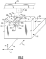
- Figure 2 illustrates a representative portion from the turbine section 28 of the engine 20.
- the engine central longitudinal axis A, radial direction R, and tangential (circumferential) direction T are superimposed in the figure to show the relative orientation of the features.
- the first component 62 bounds a portion of the core gas path C of the engine 20, and the second component is outside of the core gas path C, radially outwards of the first component.
- Terms such as “inner” and “outer” used herein refer to location with respect to the engine central longitudinal axis A, i.e., radially inner or radially outer.
- first and second used herein is to differentiate that there are two architecturally distinct components or features. It is to be further understood that the terms “first” and “second” are interchangeable in that a first component or feature could alternatively be termed as the second component or feature, and vice versa.
- the first component 62 provides a radially outer bound of the core gas path C. It is to be understood, however, that the first component 62 may alternatively be at the radially inner bound of the core gas path C.
- the first component 62 may be a blade outer air seal, a platform of a vane fairing, a combustor liner, or other component in the core gas path C
- the second component 64 may be a support ring or other component outside of the core gas path C that mates with the first component 62.
- the first component 62 has a first wall 66 and the second component 64 has a second wall 68.
- Each of the walls 66/68 is a radially-extending wall that has axially-facing faces 70.
- the forward axially-facing face 70 of the second wall 68 bears against the aft axially-facing face 70 of the first wall 66.
- the first wall 66 defines a first slot 72 that extends axially there through
- the second wall 68 defines a second slot 74 that extends axially there through.
- Each slot 72/74 has open ends at the respective axially-facing faces 70 of the walls 66/68, and an open top that faces radially.
- the second slot 74 is in register with the first slot 72 such that the slots 72/74 align along the tangential direction. In general, this means that the sides of the slots 72/74 are substantially flush.
- the slots 72/74 together define a groove 76.
- the bottoms of the slots 72/74 serve as a groove floor 76a and the tangential sides of the slots 72/74 serve as first and second sides 76b/76c of the groove 76.
- the static component 78 includes an anti-rotation tab 80 that is of complementary geometry to the geometry of the groove 76.
- the tab extends radially into the groove 76 and serves to limit rotational movement of the first component 62 and the second component 64.
- the static component and anti-rotation tab 80 are formed of a metallic alloy, such as a Ni- or Co-based superalloy.
- the first and second components 62/64 are each formed of ceramic.
- the ceramic of each of the first and second components 62/64 may be independently selected from a monolithic ceramic, a ceramic matrix composite ("CMC"), or configurations that include both monolithic ceramic and CMC.
- Example ceramic material may include, but is not limited to, silicon-containing ceramics.
- the silicon-containing ceramic may be, but is not limited to, silicon carbide (SiC) and/or silicon nitride (Si 3 N 4 ).
- An example CMC may be a SiC/SiC CMC in which SiC fibers are disposed within a SiC matrix.
- “formed of” refers to the structural self-supporting bodies of the components 62/64, rather than a non-self-supporting conformal body such as a coating.
- CMC components in the core gas path C such as the first component 62 require axial, radial, and circumferential constraints to inhibit motion when loaded by gas path and/or secondary flow forces.
- metal-to-CMC interfaces between CMC components and metallic components such as the static component 78 may contribute to one or more conditions that can reduce durability.
- the durability of metal-to-CMC interfaces can be sensitive to surface-on-surface rubbing, vibration, relative thermal expansion/contraction mismatches, temperatures in CMC components that exceed the limits of metallic alloys, undesired thermo-chemical reactions (e.g., between elements in Ni-based alloys and SiC), and load mal-distribution.
- the liner 82 is attached in the groove 76 and is situated between the anti-rotation tab 80 and the sides 76b/76c of the groove 76 to limits contact and, therefore, wear.
- the liner may be formed of a Ni- or Co-based superalloy.
- Example alloys include Waspaloy, Inconel ® by Huntington Alloys Corporation, Mar-M-509, Haynes alloy, and single crystal Ni-based superalloys.
- Co-based alloy may facilitate reductions in thermo-chemical reactions.
- the material may also be selected to optimize the wear couple between the liner 82 and the anti-rotation tab 80 and/or CMC surfaces of the components 62/64.
- the liner 82 includes a liner floor 82a along the groove floor 76a and first and second ears 82b/82c that extend off of opposite circumferential sides of the liner floor 82a and along the first and second sides 76b/76c of the groove 76, respectively.
- the liner floor 82a and ears 82b/82c define a receptacle 82d there between that receives the anti-rotation tab 80.
- the liner 82 may be secured in the groove 76 by friction fit but is not limited thereto and may additionally or alternatively utilize other mechanical attachments.
- the liner 82 may be installed into the groove 76 prior to insertion of the anti-rotation tab 80 into the receptacle 82d. In this regard, the liner 82 may initially serve to maintain the slots 72/74 of the components 62/64 in alignment prior to insertion of the anti-rotation tab 80.
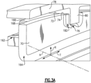
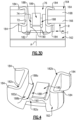
- Figures 3A , 3B , 3C , and 3D illustrate a further example of the present disclosure.
- Figure 3A is a view looking toward the axially-aft face 70 of the second wall 168 of the second component 164;
- Figure 3B is a view looking toward the axially forward face 70 of the first wall 166 of the first component 162;
- Figure 3C is a view similar to Figure 3A but without the static component 78; and
- Figure 3D is a view of the immediate region of the groove 76 without the static component 78.
- the first component 162 is a portion of a vane arc segment (e.g., a platform of an airfoil fairing) and the second component 164 is a full hoop support ring.
- the full hoop support ring is a continuous ring that has no intersegment gaps or seams (i.e., unsegmented) and few or no through-holes.
- the full hoop support ring may in a ring-strut-ring configuration in which a row of airfoil vane fairing arc segments are radially constrained between inner and outer full hoop support rings.
- the full hoop support ring may have a plurality of the slots 74 around its perimeter for alignment with an equal number of slots 72 of a plurality of first components 162 arranged in a circumferential row around the ring.
- the liner 182 lines the groove 76 and is situated between the anti-rotation tab 80 and the sides of the groove 76 to reduce wear there between.
- An isolated view of the liner 182 is shown in Figure 4 .
- the liner 182 has a liner floor 182a and first and second ears 182b/182c that extend off opposite circumferential sides of the liner floor 182a and define the receptacle 182d there between.
- each of the ears 182b/182c has a pair of axially spaced-apart clip arms 184.
- the pair of clip arms 184 on the ear 182b open in an opposite circumferential direction of the pair of clip arms 184 on the ear 182c.
- the clip arms 184 include an elbow or bend at the base of the respective ear 182b/182c so as to render the arms 184 flexible.
- the spacing between the clips arms 184 is smaller than the combined thickness of the walls 166/168.
- the clip arms 184 pinch on the walls 166/168 on each side of the liner 182 ( Figure 3D ).
- the flexibility of the clip arms 184 permits that arms to spread apart to receive the walls 166/168. Once spread open, the arms are biased via the elbow to spring back to the initial, un-spread position. This bias serves to produce a pinching force and thus facilitates radial and circumferential retention of the liner 182 in the groove 76, reduction in vibration, and take up component tolerances.
- the ears 182b/182c may also be spread apart from each other by a distance that is greater than the width of the groove 76 in the circumferential direction. Upon insertion of the liner 182 into the groove 76 the ears 182b/182c are compressed toward each other. Once compressed, the ears 182b/182c are biased to spring back to the initial, un-compressed position. This bias serves to further facilitate circumferential and radial retention of the liner 182 in the groove 76, reduce vibration, and take up component tolerances.
- the liner floor 182a includes a cantilevered tab 186.
- the tab 186 is flanked (circumferentially) by two slots 188 that extend between the ears 182b/182c and the tab 186.
- the tab 186 slopes upwards from the remainder of the liner floor 182a so as to be raised from the lowest underside surface of the liner floor 182a (that contacts the groove floor 76a).
- the tab 186 is flexible in the radial direction.
- the spring force of the tab 186 serves to bias the liner 182 toward the groove floor 76a. This bias further serves to retain the liner 182 in the groove 76, reduce vibration, and also take up mismatches in thermal expansion/contraction between the metallic static component 78 and the ceramic components 162/164.
- Each of the slots 188 has an open end 188a near the tip end of the tab 186 and a terminal end 188b near the base of the tab 186.
- At the terminal ends 188b there are respective bridges 190 that connect the liner floor 182a to the ears 182b/182c.
- Each bridge 190 is a relatively narrow band that serves as a spring flexion for the ears 182b/182c as discussed above.
- the liner 182 may be formed from sheet metal, it is not limited thereto and other manufacturing techniques are also applicable.
- the biases of the liner 182 may also serve to re-distribute stresses in the event that either of the components 162/164 tilts. Such a tilt may otherwise result in the concentration of stresses at a point or line of contact.
- the spring forces described above operate to re-distribute such stresses across the liner 182 and thus facilitate reduction in stress concentrations.
Landscapes
- Engineering & Computer Science (AREA)
- Mechanical Engineering (AREA)
- General Engineering & Computer Science (AREA)
- Chemical & Material Sciences (AREA)
- Materials Engineering (AREA)
- Turbine Rotor Nozzle Sealing (AREA)
Applications Claiming Priority (1)
| Application Number | Priority Date | Filing Date | Title |
|---|---|---|---|
| US17/743,544 US11834967B1 (en) | 2022-05-13 | 2022-05-13 | Liner for anti-rotation tab and ceramic component |
Publications (2)
| Publication Number | Publication Date |
|---|---|
| EP4276286A1 true EP4276286A1 (de) | 2023-11-15 |
| EP4276286B1 EP4276286B1 (de) | 2026-02-18 |
Family
ID=86382800
Family Applications (1)
| Application Number | Title | Priority Date | Filing Date |
|---|---|---|---|
| EP23173360.1A Active EP4276286B1 (de) | 2022-05-13 | 2023-05-15 | Auskleidung für drehsicherungslasche und keramisches bauteil |
Country Status (2)
| Country | Link |
|---|---|
| US (1) | US11834967B1 (de) |
| EP (1) | EP4276286B1 (de) |
Citations (4)
| Publication number | Priority date | Publication date | Assignee | Title |
|---|---|---|---|---|
| EP3351738A2 (de) * | 2017-01-19 | 2018-07-25 | United Technologies Corporation | Zweiteilige, mehrflächige verschleissschutzschicht |
| EP3587751A1 (de) * | 2018-06-27 | 2020-01-01 | United Technologies Corporation | Gasturbinenmotorkomponente |
| EP3653843A1 (de) * | 2018-11-19 | 2020-05-20 | United Technologies Corporation | Luftdichtungsschnittstelle mit vorwärtseingriffsmerkmalen und aktiver abstandssteuerung für eine gasturbine |
| US20200158023A1 (en) * | 2018-11-19 | 2020-05-21 | United Technologies Corporation | Air seal interface with aft engagement features and active clearance control for a gas turbine engine |
Family Cites Families (6)
| Publication number | Priority date | Publication date | Assignee | Title |
|---|---|---|---|---|
| US10605087B2 (en) * | 2017-12-14 | 2020-03-31 | United Technologies Corporation | CMC component with flowpath surface ribs |
| FR3085412B1 (fr) * | 2018-08-31 | 2020-12-04 | Safran Aircraft Engines | Secteur de distributeur d'une turbomachine comprenant une encoche anti-rotation a insert d'usure |
| US10753221B2 (en) | 2018-12-12 | 2020-08-25 | Raytheon Technologies Corporation | Seal assembly with ductile wear liner |
| US11313233B2 (en) * | 2019-08-20 | 2022-04-26 | Rolls-Royce Corporation | Turbine vane assembly with ceramic matrix composite parts and platform sealing features |
| US11454130B2 (en) | 2019-09-11 | 2022-09-27 | Raytheon Technologies Corporation | Blade outer air seal with inward-facing dovetail hooks and backside cooling |
| US11220930B2 (en) | 2019-12-03 | 2022-01-11 | Rolls-Royce Corporation | Assembly with pin-mounted ceramic matrix composite material components |
-
2022
- 2022-05-13 US US17/743,544 patent/US11834967B1/en active Active
-
2023
- 2023-05-15 EP EP23173360.1A patent/EP4276286B1/de active Active
Patent Citations (4)
| Publication number | Priority date | Publication date | Assignee | Title |
|---|---|---|---|---|
| EP3351738A2 (de) * | 2017-01-19 | 2018-07-25 | United Technologies Corporation | Zweiteilige, mehrflächige verschleissschutzschicht |
| EP3587751A1 (de) * | 2018-06-27 | 2020-01-01 | United Technologies Corporation | Gasturbinenmotorkomponente |
| EP3653843A1 (de) * | 2018-11-19 | 2020-05-20 | United Technologies Corporation | Luftdichtungsschnittstelle mit vorwärtseingriffsmerkmalen und aktiver abstandssteuerung für eine gasturbine |
| US20200158023A1 (en) * | 2018-11-19 | 2020-05-21 | United Technologies Corporation | Air seal interface with aft engagement features and active clearance control for a gas turbine engine |
Also Published As
| Publication number | Publication date |
|---|---|
| US20230366322A1 (en) | 2023-11-16 |
| EP4276286B1 (de) | 2026-02-18 |
| US11834967B1 (en) | 2023-12-05 |
Similar Documents
| Publication | Publication Date | Title |
|---|---|---|
| EP3219935B1 (de) | Turbinenmotorschaufelspaltdichtung mit lastübertragender halterung | |
| EP3219933B1 (de) | Dichtungsanordnung, gasturbine damit sowie verfahren zur montage einer dichtungsanordnung | |
| EP3219924B1 (de) | Äussere laufschaufelluftdichtung eines turbinenmotors mit lastübertragender abdeckplatte | |
| US20210071542A1 (en) | Blade outer air seal with face seal | |
| EP3219938A1 (de) | Träger für eine laufschaufelspitzendichtung, zugehörige verfahren zum schutz einer laufschaufelspitzendichtung und laufschaufelspitzendichtungsanordnung | |
| EP3219923B1 (de) | Dichtungsverdrehsicherung | |
| EP3219934B1 (de) | Dichtungssatz für gasturbinentriebwerk | |
| EP3892822B1 (de) | Leitschaufelträgersystem | |
| EP3219928B1 (de) | Äussere luftdichtung für eine turbinenschaufel mit federzentrierung | |
| EP3805530A1 (de) | Schaufelluftdichtung eines gasturbinentriebwerks und entprechendes montageverfahren | |
| US12454893B2 (en) | Airfoil anti-rotation ring and assembly | |
| EP4317648A1 (de) | Schaufelgitter mit miteinander verbundenen singulett-schaufeln | |
| EP4276286B1 (de) | Auskleidung für drehsicherungslasche und keramisches bauteil | |
| EP4517051A1 (de) | Radialdichtung zwischen cmc-schaufel und schaufelträger | |
| EP3228830B1 (de) | Äussere luftdichtung für eine turbinenschaufel mit zentral montierten dichtungsbogensegmenten | |
| EP3819474A1 (de) | Plattformdichtung für ein gasturbinentriebwerk | |
| EP4283097A1 (de) | Turbinenmotor mit tangentialem on-bordinjektor (tobi) stützschaufeln | |
| US12523157B2 (en) | Ceramic vane ring-strut-ring attachment configuration |
Legal Events
| Date | Code | Title | Description |
|---|---|---|---|
| PUAI | Public reference made under article 153(3) epc to a published international application that has entered the european phase |
Free format text: ORIGINAL CODE: 0009012 |
|
| STAA | Information on the status of an ep patent application or granted ep patent |
Free format text: STATUS: THE APPLICATION HAS BEEN PUBLISHED |
|
| AK | Designated contracting states |
Kind code of ref document: A1 Designated state(s): AL AT BE BG CH CY CZ DE DK EE ES FI FR GB GR HR HU IE IS IT LI LT LU LV MC ME MK MT NL NO PL PT RO RS SE SI SK SM TR |
|
| STAA | Information on the status of an ep patent application or granted ep patent |
Free format text: STATUS: REQUEST FOR EXAMINATION WAS MADE |
|
| 17P | Request for examination filed |
Effective date: 20240515 |
|
| RBV | Designated contracting states (corrected) |
Designated state(s): AL AT BE BG CH CY CZ DE DK EE ES FI FR GB GR HR HU IE IS IT LI LT LU LV MC ME MK MT NL NO PL PT RO RS SE SI SK SM TR |
|
| RIC1 | Information provided on ipc code assigned before grant |
Ipc: F01D 25/24 20060101AFI20250715BHEP |
|
| GRAP | Despatch of communication of intention to grant a patent |
Free format text: ORIGINAL CODE: EPIDOSNIGR1 |
|
| STAA | Information on the status of an ep patent application or granted ep patent |
Free format text: STATUS: GRANT OF PATENT IS INTENDED |
|
| INTG | Intention to grant announced |
Effective date: 20250908 |
|
| GRAS | Grant fee paid |
Free format text: ORIGINAL CODE: EPIDOSNIGR3 |
|
| GRAA | (expected) grant |
Free format text: ORIGINAL CODE: 0009210 |
|
| STAA | Information on the status of an ep patent application or granted ep patent |
Free format text: STATUS: THE PATENT HAS BEEN GRANTED |
|
| AK | Designated contracting states |
Kind code of ref document: B1 Designated state(s): AL AT BE BG CH CY CZ DE DK EE ES FI FR GB GR HR HU IE IS IT LI LT LU LV MC ME MK MT NL NO PL PT RO RS SE SI SK SM TR |
|
| REG | Reference to a national code |
Ref country code: CH Ref legal event code: F10 Free format text: ST27 STATUS EVENT CODE: U-0-0-F10-F00 (AS PROVIDED BY THE NATIONAL OFFICE) Effective date: 20260218 Ref country code: GB Ref legal event code: FG4D |
|
| REG | Reference to a national code |
Ref country code: IE Ref legal event code: FG4D |
|
| REG | Reference to a national code |
Ref country code: DE Ref legal event code: R096 Ref document number: 602023012059 Country of ref document: DE |