EP4276287A2 - Système d'entraînement d'aéronef avec dispositif de traitmenet de gaz d'échappement, et procédé de traitement d'un flux de gaz d'échappement - Google Patents
Système d'entraînement d'aéronef avec dispositif de traitmenet de gaz d'échappement, et procédé de traitement d'un flux de gaz d'échappement Download PDFInfo
- Publication number
- EP4276287A2 EP4276287A2 EP23192228.7A EP23192228A EP4276287A2 EP 4276287 A2 EP4276287 A2 EP 4276287A2 EP 23192228 A EP23192228 A EP 23192228A EP 4276287 A2 EP4276287 A2 EP 4276287A2
- Authority
- EP
- European Patent Office
- Prior art keywords
- exhaust gas
- gas stream
- turbomachine
- evaporator
- condenser
- Prior art date
- Legal status (The legal status is an assumption and is not a legal conclusion. Google has not performed a legal analysis and makes no representation as to the accuracy of the status listed.)
- Withdrawn
Links
- 238000000034 method Methods 0.000 title claims abstract 6
- XLYOFNOQVPJJNP-UHFFFAOYSA-N water Substances O XLYOFNOQVPJJNP-UHFFFAOYSA-N 0.000 claims abstract 14
- 239000012080 ambient air Substances 0.000 claims abstract 12
- 238000002156 mixing Methods 0.000 claims 11
- 239000003990 capacitor Substances 0.000 claims 2
- 238000002485 combustion reaction Methods 0.000 claims 2
- 238000001704 evaporation Methods 0.000 claims 2
- 238000011144 upstream manufacturing Methods 0.000 claims 2
- 238000001816 cooling Methods 0.000 claims 1
- 238000001556 precipitation Methods 0.000 claims 1
- 230000002040 relaxant effect Effects 0.000 claims 1
- 238000000926 separation method Methods 0.000 claims 1
- 239000007921 spray Substances 0.000 claims 1
Images


Classifications
-
- F—MECHANICAL ENGINEERING; LIGHTING; HEATING; WEAPONS; BLASTING
- F01—MACHINES OR ENGINES IN GENERAL; ENGINE PLANTS IN GENERAL; STEAM ENGINES
- F01K—STEAM ENGINE PLANTS; STEAM ACCUMULATORS; ENGINE PLANTS NOT OTHERWISE PROVIDED FOR; ENGINES USING SPECIAL WORKING FLUIDS OR CYCLES
- F01K23/00—Plants characterised by more than one engine delivering power external to the plant, the engines being driven by different fluids
- F01K23/02—Plants characterised by more than one engine delivering power external to the plant, the engines being driven by different fluids the engine cycles being thermally coupled
- F01K23/06—Plants characterised by more than one engine delivering power external to the plant, the engines being driven by different fluids the engine cycles being thermally coupled combustion heat from one cycle heating the fluid in another cycle
- F01K23/10—Plants characterised by more than one engine delivering power external to the plant, the engines being driven by different fluids the engine cycles being thermally coupled combustion heat from one cycle heating the fluid in another cycle with exhaust fluid of one cycle heating the fluid in another cycle
-
- F—MECHANICAL ENGINEERING; LIGHTING; HEATING; WEAPONS; BLASTING
- F02—COMBUSTION ENGINES; HOT-GAS OR COMBUSTION-PRODUCT ENGINE PLANTS
- F02C—GAS-TURBINE PLANTS; AIR INTAKES FOR JET-PROPULSION PLANTS; CONTROLLING FUEL SUPPLY IN AIR-BREATHING JET-PROPULSION PLANTS
- F02C3/00—Gas-turbine plants characterised by the use of combustion products as the working fluid
- F02C3/20—Gas-turbine plants characterised by the use of combustion products as the working fluid using a special fuel, oxidant, or dilution fluid to generate the combustion products
- F02C3/30—Adding water, steam or other fluids for influencing combustion, e.g. to obtain cleaner exhaust gases
- F02C3/305—Increasing the power, speed, torque or efficiency of a gas turbine or the thrust of a turbojet engine by injecting or adding water, steam or other fluids
-
- F—MECHANICAL ENGINEERING; LIGHTING; HEATING; WEAPONS; BLASTING
- F05—INDEXING SCHEMES RELATING TO ENGINES OR PUMPS IN VARIOUS SUBCLASSES OF CLASSES F01-F04
- F05D—INDEXING SCHEME FOR ASPECTS RELATING TO NON-POSITIVE-DISPLACEMENT MACHINES OR ENGINES, GAS-TURBINES OR JET-PROPULSION PLANTS
- F05D2220/00—Application
- F05D2220/30—Application in turbines
- F05D2220/32—Application in turbines in gas turbines
- F05D2220/323—Application in turbines in gas turbines for aircraft propulsion, e.g. jet engines
Definitions
- the present invention relates to an exhaust gas treatment device, an aircraft propulsion system with such an exhaust gas treatment device and a method for treating an exhaust gas stream.
- the exhaust treatment device utilizes exhaust gas energy and reduces contrails caused by condensation after expansion.
- Airplanes are usually powered by heat engines in combination with suitable propulsion generators (propulsors). Propellers and fans (so-called “fans” ) are used to generate propulsion, and the exhaust gas jet from the heat engine also contributes to propulsion.
- Propellers and fans are used to generate propulsion, and the exhaust gas jet from the heat engine also contributes to propulsion.
- the most commonly used heat engines are piston engines and gas turbines, although today piston engines are only used in relatively small aircraft.
- Fossil fuels are currently used almost exclusively as energy sources. There were also experiments with liquid hydrogen or liquid natural gas. The combustion of these fuels creates undesirable environmental pollution that contributes to climate change.
- the combustion of fossil fuels mainly produces carbon dioxide (CO 2 ) and water (H 2 0), but also nitrogen oxides (N0 x ), sulfur oxides (S0 x ), unburned hydrocarbons (C x H y ), carbon monoxide (CO), etc. can be found in the exhaust gas.
- When using hydrogen mainly water and, due to the high process temperatures, also nitrogen oxides (NO x ) are produced.
- the water present in the exhaust gas creates contrails under certain conditions. These are formed when the warm, moist exhaust gas mixes with colder ambient air. Microscopically small ones form on so-called condensation nuclei (e.g. dust/soot particles or electrically charged molecules). Drops of water or - if the ambient temperature is low enough - tiny ice crystals.
- condensation nuclei e.g. dust/soot particles or electrically charged molecules
- US 7,971,438 B2 discloses an aircraft propulsion system in which the formation of contrails occurs by condensing out the water vapor present in the exhaust gas before it is released into the atmosphere.
- the proposed system consists of a gas turbine with a system of heat exchangers (recuperators).
- a first heat exchanger is arranged downstream of the last turbine stage. This transfers exhaust gas energy to the air supplied by the compressor before it enters the combustion chamber, which cools the exhaust gas.
- the cooled (dry) exhaust gas is then passed through a third heat exchanger. This is used for intermediate cooling during compression ( “Intercooler” ) . Here it is heated again and then mixed with the bypass air - which previously flowed through the condenser - and expanded in a common nozzle.
- the recuperators are pure gas/gas heat exchangers. Since these work at low pressure and with small temperature differences, they are very voluminous and therefore heavy and also generate large pressure losses. Especially that one Condenser works on both flow sides at low pressure and with a small temperature difference, and it should also be arranged in the side stream - where the flow velocity is very high.
- US 3,978,661 B1 discloses a heat engine in which a gas turbine process and a steam process are used in parallel.
- An evaporator through which the exhaust gas flows is arranged downstream of the last turbine.
- the steam generated is introduced into the combustion chamber of the heat engine, resulting in a high specific enthalpy at the combustion chamber outlet.
- the exhaust gas is then passed through a condenser, where it is cooled until the water it contains condenses out - at least partially.
- GB 2 531 632 A discloses a mechanical device having a swirl vessel that can be externally attached to an exhaust port of an aircraft gas turbine engine to suppress the formation of contrails.
- the exhaust gases are introduced into the device and come into contact with turbine blades, causing the vessel and consequently the gases to rotate to centrifugally separate moisture from the gases. Any residual heat in the dewatered flow is partially recovered by thermal energy requirements before the water is disposed of.
- An object of the embodiments of the present invention is to provide an exhaust gas treatment device, an aircraft propulsion system and a method for treating an exhaust gas stream, each of which can achieve higher thermal efficiency through efficient use of exhaust gas energy and minimize the formation of contrails.
- an exhaust gas treatment device for treating an exhaust gas stream from a turbomachine has a condenser which condenses at least part of a water contained in the exhaust gas stream from the turbomachine and thereby emits a first energy; an evaporator which evaporates at least part of the water condensed in the condenser and thereby absorbs a second energy which is taken from the exhaust gas stream from the turbomachine; a turbine driven by steam discharged from the evaporator and expanding the steam; a fan that supplies ambient air to the condenser so that it absorbs the first energy; and at least one outlet device from which the ambient air emitted by the condenser and/or a dehumidified exhaust gas stream is exhausted from the condenser.
- a corresponding method for treating an exhaust gas stream from a turbomachine has steps for condensing at least part of a water contained in the exhaust gas stream from the turbomachine in a condenser, with a first energy being released; for evaporating at least part of the water condensed in the condenser in an evaporator, thereby absorbing a second energy which is taken from the exhaust gas stream from the turbomachine; for driving a turbine by steam discharged from the evaporator and expanding the steam; for driving a fan to supply ambient air to the condenser to absorb the first energy; and for exhausting the ambient air emitted by the condenser and/or a dehumidified exhaust gas stream from the condenser from at least one outlet device.
- an exhaust gas treatment device for treating an exhaust gas stream from a turbomachine has a fan that emits ambient air; a mixing device which mixes the ambient air emitted by the fan with at least a portion of the exhaust gas stream from the turbomachine, so that at least a portion of a water contained in the exhaust gas stream condenses; an evaporator which evaporates at least part of the water condensed in the mixing device and thereby absorbs energy which is taken from the exhaust gas stream from the turbomachine; a turbine driven by steam discharged from the evaporator and expanding the steam; and an outlet device from which at least a portion of the exhaust gas stream mixed with the ambient air and dehumidified is discharged from the mixing device.
- a corresponding method for treating an exhaust gas stream from a turbomachine has steps for discharging ambient air through a fan; for mixing the ambient air emitted by the fan with at least part of the exhaust gas stream from the turbomachine by a mixing device, so that at least part of the water contained in the exhaust gas stream condenses; for evaporating at least part of the water condensed in the mixing device through an evaporator, which thereby absorbs energy that is taken from the exhaust gas stream from the turbomachine; for driving a turbine by steam discharged from the evaporator to expand the steam; and for exhausting at least a portion of the exhaust gas stream mixed with the ambient air and dehumidified from the mixing device from an outlet device.
- a cooling device is arranged in the exhaust gas flow upstream of the mixing device, which cools at least part of the exhaust gas flow from the turbomachine and thereby releases energy.
- the size can be further reduced because a separate capacitor is not required.
- a separating device is preferably arranged in the exhaust gas stream downstream of the condenser or downstream of the mixing device, which separates the condensed water released by the condenser or by the mixing device and feeds it to the evaporator.
- the separation device has a spray electrode, a precipitation electrode and/or a swirl generator, whereby the water separation can be optimized.
- the entire exhaust gas energy can still be present in the nozzles during the expansion and the separating device can have a small volume flow, which therefore has relatively small dimensions and carries out the water separation effectively.
- the water present in the exhaust gas of the heat engine is condensed - at least to a large extent.
- the resulting water is recovered and used for a semi-open cycle.
- the fan can be driven by the turbine or by an auxiliary turbine, which in turn is driven by an exhaust stream from the evaporator.
- the steam expanded in the turbine is preferably introduced into a combustion chamber of the turbomachine and/or used to cool components in a hot area of the turbomachine, which contributes to increasing the thermal efficiency.
- a condensate pump, a water treatment device, a water reservoir and/or a feed water pump are arranged in the exhaust gas stream downstream of the condenser or downstream of the mixing device and upstream of the evaporator, whereby the supply of the separated water to the evaporator can be improved .
- the condensate pump, the water treatment device, the water storage and/or the feed water pump is arranged downstream of a separator.
- the fan can be driven by the turbine or by an auxiliary turbine, which in turn is driven by the exhaust gas flow from the evaporator.
- one or more, in particular all, steps of the method can be carried out completely or partially automatically, in particular by a control or its means.
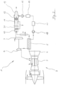
- Fig.1 shows schematically an embodiment of an aircraft propulsion system 1 according to the invention.
- the aircraft propulsion system 1 has a turbomachine 2 in the form of a heat engine and an exhaust gas treatment device described below.
- the turbomachine 2 has a combustion chamber 3 and a low-pressure turbine 4.
- the exhaust gases from the heat engine 2 are not, as is usually the case, released directly into the atmosphere, where they mix with the ambient air and then form contrails, but are passed through an evaporator 5 arranged downstream of the low-pressure turbine 4. There, energy is removed from the exhaust gas to produce water vapor, which reduces the exhaust gas temperature.
- the water supplied to the evaporator 5 was previously brought to a pressure by means of a feed water pump 18 that is significantly higher than the pressure in the combustion chamber 3 of the turbomachine 2.
- the high-pressure steam generated in the evaporator 5 is expanded via at least one turbine 6 in the form of a steam turbine to a pressure level that is just above that of the combustion chamber 3.
- the steam can then be introduced directly into the combustion chamber 3 and/or used to cool components in the hot area.
- the specific enthalpy at the outlet of the combustion chamber 3 is larger because of the high specific heat capacity of the water compared to an engine without steam as a working medium.
- the steam introduced into the combustion chamber 3 increases the mass flow and thus the performance of the aircraft propulsion system 1. No volume change work has to be provided for the additional mass flow.
- the pressure can be built up in the feed water pump 18 in the liquid state. As a result, the specific useful power increases significantly and the required performance is achieved with a significantly lower mass throughput - compared to a conventional engine.
- the turbine 6 in turn drives a fan 7.
- the fan 7 conveys cold ambient air through a condenser 8, which in the first embodiment is in the exhaust gas stream is arranged downstream of the evaporator 5.
- the extracted ambient air absorbs energy from the exhaust gas flow.
- the heated ambient air is then expanded in a nozzle 14 or, alternatively, mixed with the exhaust gas in front of the core engine nozzle 13.
- the fan 7 can also be driven indirectly (for example by an electric motor).
- the steam turbine 6 can drive a generator or feed its power into the turbomachine 2.
- the gas/water mixture is then passed into a separation device 9 in the form of a separation channel and then expanded in the core engine nozzle 13.
- the water molecules are electrostatically charged, for example by means of a spray electrode 10 using the corona charging process (shock ionization).
- the complementary pole is placed on a precipitation electrode 11 on the surface of the deposition channel 9.
- the electrostatic forces cause the water drops to move towards a wall of the separation channel 9, where the water is collected further downstream.
- the inertia and the difference in density between the water droplets and the gas mixture can be exploited (for example by a cyclone, a swirl generator, a abrupt deflection, etc.).
- a swirl generator 12 is shown as an example. In principle, other separation processes known from process engineering for water separation can be used.
- the separated water is sucked off by a condensate pump 15 and then passed into a water reservoir 17 via a water treatment device 16.
- the remaining, cleaned exhaust gas stream without the separated water can be exhausted from the core engine nozzle 13.
- the water contained in the exhaust gas flow from the heat engine 2 passes through the evaporator 5, the condenser 8, the separator 9, the condensate pump 15, the water treatment device 16, the water storage 17, the feed water pump 18, the evaporator 5, in this order Turbine 6 and possibly the combustion chamber 3 or the components in the hot area.
- the cleaned exhaust gas from the exhaust gas stream from the heat engine 2 leaves the circuit after the separation device 9 and is discharged from the core engine nozzle 13, for example.
- the flow of ambient air in the first embodiment passes through the fan 7, the condenser 8 and the nozzle 14 in this order or is at least partially mixed with the cleaned exhaust gas and discharged from the core engine nozzle 13.
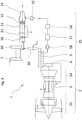
- Fig.2 schematically shows an alternative embodiment of the present invention.
- the reference numbers are largely the same as those of Fig.1 identical.
- a cooling device 20 is arranged in the form of a connecting channel in the exhaust gas stream downstream of the evaporator 5.
- the cooling device 20 cools at least part of the exhaust gas flow from the turbomachine 2 and thereby releases energy.
- the main difference from the first embodiment is that in the second embodiment no condenser 8 is used and the cold ambient air conveyed by the fan 7 is mixed with the already cooled exhaust gas in a mixing device 21 in the form of a mixing channel.
- the mixing device 21 is arranged in the exhaust gas stream downstream of the evaporator 5.
- the water contained in the exhaust gas stream from the heat engine 2 passes through the evaporator 5, the cooling device 20, the mixing device 21, the condensate pump 15, the water treatment device 16, the water storage 17, the feed water pump 18, the evaporator 5, in this order Turbine 6 and possibly the combustion chamber 3 or the components in the hot area.
- the cleaned exhaust gas leaves the circuit after the mixing device 21 and is discharged from the core engine nozzle 13, for example.
- the flow of ambient air in the second embodiment passes through the blower 7, the mixing device 21 in this order, and is then at least partially discharged from the core engine nozzle 13 with the cleaned exhaust gas.
- the fan 7 and the mixing device 21 are arranged away from the heat engine 2.
- the cooling device 20 between the evaporator 5 and the mixing device 21 can preferably be arranged without insulation along a surface of an aircraft (for example on the wing, on the fuselage, etc.), whereby the exhaust gas transfers heat to the environment before it is mixed in the mixing device 21 gives away.
- the exhaust gas cools down and is then passed into the mixing device 21, where cold ambient air is mixed in until the water contained condenses.
- the water separation and treatment takes place as in the first embodiment.
- condensation can take place in the second embodiment without a heat exchanger (condenser).
- the heat released from the cooling device 20 to the environment represents a loss because the enthalpy of the exhaust gas is reduced before expansion in the core engine nozzle 13.
- Fig. 3 shows an aircraft propulsion system according to a third embodiment of the present invention. Those components that are the same or similar to the components of the first embodiment have the same reference numerals.
- a steam / water recovery system 25 is arranged downstream of the heat engine 2.
- Ambient air is conveyed from a compressor area 23 of the heat engine 2 into the combustion chamber 3 with an increase in pressure.
- the steam generated is mixed in there. Because of the high specific heat capacity of water, the combustion of fuel produces a working gas with a very high specific enthalpy.
- Part of the expansion takes place in a turbine area 24 of the heat engine 2, with the temperature of the exhaust gas at the outlet still being relatively high.
- the water in the exhaust gas in liquid form In order to keep the water in the exhaust gas in liquid form, it must be cooled below the so-called dew point. At the dew point, the relative humidity has increased to 100% and has therefore reached saturation. With further cooling, the saturation vapor pressure decreases much faster than the water partial pressure, resulting in supersaturation. Small drops of water form on condensation nuclei. Once the temperature falls below the dew point, the water contained is - at least partially - in liquid form.
- An evaporator 5 is arranged downstream of the turbine area 24 of the heat engine 2. There, energy is removed from the exhaust gas to produce water vapor, which further reduces its temperature. The exhaust gas is then passed through the (further) heat exchanger 8 and from there into an auxiliary turbine 22. After the expansion in the auxiliary turbine 22, the exhaust gas temperature is lower than the dew point temperature, and the water contained is - at least partially - in liquid form.
- the auxiliary turbine 22 drives the fan 7.
- the fan 7 conveys cold ambient air through the heat exchanger 8. Exhaust gas energy is transferred to the air conveyed by the fan 7, which heats up and is then relaxed in a nozzle 14 or, alternatively, mixed with the exhaust gas in front of the core engine nozzle 13.
- the fan 7 can also be driven indirectly (for example by an electric motor).
- the auxiliary turbine 22 would drive a generator or feed its power into the heat engine 2.
- the exhaust gas Downstream of the auxiliary turbine 22, the exhaust gas is passed into the separation device (separation channel) 9 and then expanded in the core engine nozzle 13.
- the separation device 9 the water molecules are electrostatically charged, for example by means of the spray electrode 10, using the corona charging process (shock ionization).
- the complementary pole is applied to the precipitation electrode 11 on the surface or on a channel wall of the separation device 9.
- the electrostatic forces cause the water droplets to move towards the canal wall, where the water is collected further downstream.
- the inertia and the difference in density between the water droplets and the gas mixture can be exploited (for example by a cyclone, a swirl generator, a abrupt deflection).
- a swirl generator 12 is shown as an example. In principle, all separation processes known from process engineering for water separation can be used.
- the separated water is sucked off by the condensate pump 15 and then passed into the water reservoir 17 via the water treatment device 16.
- the water vapor is brought to a pressure by means of the feed water pump 18 which is at least slightly higher than the pressure in the combustion chamber 3 of the heat engine 2.
- the steam generated can be introduced directly into the combustion chamber 3 of the heat engine 2 and/or for cooling components in the Hot area can be used.
- the steam can advantageously be brought to a significantly higher pressure.
- the high-pressure steam generated is expanded by means of at least the turbine (steam turbine 6) to a pressure level that is just above that of the combustion chamber 3.
- the power of the turbine 6 can, as shown, be fed directly to a shaft of the heat engine 2 or used to drive auxiliary units. This allows the efficiency of the heat engine 2 to be further increased.
- the water contained in the exhaust gas stream from the heat engine 2 passes through the evaporator 5, the condenser 8, the auxiliary turbine 22, the separator 9, the condensate pump 15, the water treatment device 16, the water storage 17, the feed water pump 18 in this order Evaporator 5, the turbine 6 and possibly the combustion chamber 3 or the components in the hot area.
- the cleaned exhaust gas from the exhaust gas stream from the heat engine 2 leaves the circuit after the separation device 9 and is discharged from the core engine nozzle 13, for example.
- the flow of ambient air in the third embodiment passes through the fan 7, the condenser 8 and the nozzle 14 in this order or is at least partially mixed with the cleaned exhaust gas and discharged from the core engine nozzle 13.
- the proposed propulsion system offers a number of advantages over a conventional engine or conventional propulsion systems:
- the steam introduced into the combustion chamber 3 increases the mass flow and thus the performance of the turbine area 24.
- No volume change work has to be provided for the additional mass flow, since the pressure build-up in the feed water pump 18 takes place in the liquid state.
- the specific useful power increases significantly, and the required performance is achieved with a significantly lower mass throughput.
- all components compressors, turbines, heat exchangers such as evaporators and condensers, etc.
- the optimal overall pressure ratio is below that of a conventional engine. This allows the number of compressor and turbine stages to be reduced, which also has a positive effect on the weight and size.
- the separating device 9 has a relatively small volume flow and therefore relatively small dimensions. Water separation can be carried out effectively.
- climate-impacting emissions can be significantly reduced because a) the efficient use of exhaust energy and the reduced power requirement when compressing the working medium reduces the specific fuel consumption, and b) the heat supply in the combustion chamber 3 in the presence of water reduces the formation of nitrogen oxides (NOx) greatly reduced.
- NOx nitrogen oxides
- Fig. 4 shows an aircraft propulsion system according to a fourth embodiment of the present invention. Those components that are the same or similar to the components of the second embodiment have the same reference numerals.
- the main difference from the third embodiment is that in the fourth embodiment no condenser 8 is used and that the cold ambient air conveyed by the fan 7 is mixed with the already cooled down exhaust gas in the mixing device (mixing channel) 21.
- the exhaust gas is passed via a cooling device (connecting channel) 20 to the auxiliary turbine 22 and expanded there.
- the cooling device 20 can advantageously be arranged away from the heat engine 2.
- the cooling device 20 between the evaporator 5 and the auxiliary turbine 22 can preferably be arranged along the surface of the aircraft (for example on the wing, on the fuselage, etc.) and more preferably without insulation, whereby the exhaust gas cools down before expansion in the auxiliary turbine 22 by releasing heat into the environment.
- the exhaust gas is then passed into the mixing device 21, where as much cold ambient air is mixed in by the fan 7 until the water contained condenses.
- the water separation and treatment takes place as in the third embodiment Fig. 3 .
- condensation By lowering the temperature, releasing energy into the environment and mixing it with cold ambient air, condensation can take place without a heat exchanger (condenser 8). However, the heat released from the cooling device 20 to the environment represents a loss because the enthalpy of the exhaust gas is reduced before expansion in the core engine nozzle 13.
- the power of the turbine 6, as shown, can be fed directly to a shaft of the heat engine 2 or used to drive auxiliary units. This allows the efficiency of the heat engine 2 to be further increased.
- the water contained in the exhaust gas stream from the heat engine 2 passes through the evaporator 5, the cooling device 20, the auxiliary turbine 22, the mixing device 21, the condensate pump 15, the water treatment device 16, the water storage 17, the feed water pump 18, in this order Evaporator 5, the turbine 6 and possibly the combustion chamber 3 or the components in the hot area.
- the cleaned exhaust gas leaves the circuit after the mixing device 21 and is discharged from the core engine nozzle 13, for example.
- the flow of ambient air in the fourth embodiment passes through the blower 7, the mixing device 21 in this order, and is then at least partially discharged from the core engine nozzle 13 with the cleaned exhaust gas.
Landscapes
- Engineering & Computer Science (AREA)
- Chemical & Material Sciences (AREA)
- Combustion & Propulsion (AREA)
- Mechanical Engineering (AREA)
- General Engineering & Computer Science (AREA)
- Engine Equipment That Uses Special Cycles (AREA)
- Aviation & Aerospace Engineering (AREA)
- Drying Of Gases (AREA)
Applications Claiming Priority (3)
| Application Number | Priority Date | Filing Date | Title |
|---|---|---|---|
| DE102018208026.7A DE102018208026A1 (de) | 2018-05-22 | 2018-05-22 | Abgasbehandlungsvorrichtung, Flugzeugantriebssystem und Verfahren zum Behandeln eines Abgasstromes |
| EP19731129.3A EP3797217B1 (fr) | 2018-05-22 | 2019-05-21 | Système d'entraînement d'aéronef avec dispositif de traitmenet de gaz d'échappement, et procédé de traitement d'un flux de gaz d'échappement |
| PCT/DE2019/000142 WO2019223823A1 (fr) | 2018-05-22 | 2019-05-21 | Dispositif de traitement de gaz d'échappement, système d'entraînement d'aéronef, et procédé de traitement d'un flux de gaz d'échappement |
Related Parent Applications (1)
| Application Number | Title | Priority Date | Filing Date |
|---|---|---|---|
| EP19731129.3A Division EP3797217B1 (fr) | 2018-05-22 | 2019-05-21 | Système d'entraînement d'aéronef avec dispositif de traitmenet de gaz d'échappement, et procédé de traitement d'un flux de gaz d'échappement |
Publications (2)
| Publication Number | Publication Date |
|---|---|
| EP4276287A2 true EP4276287A2 (fr) | 2023-11-15 |
| EP4276287A3 EP4276287A3 (fr) | 2023-12-27 |
Family
ID=66912488
Family Applications (2)
| Application Number | Title | Priority Date | Filing Date |
|---|---|---|---|
| EP19731129.3A Active EP3797217B1 (fr) | 2018-05-22 | 2019-05-21 | Système d'entraînement d'aéronef avec dispositif de traitmenet de gaz d'échappement, et procédé de traitement d'un flux de gaz d'échappement |
| EP23192228.7A Withdrawn EP4276287A3 (fr) | 2018-05-22 | 2019-05-21 | Système d'entraînement d'aéronef avec dispositif de traitmenet de gaz d'échappement, et procédé de traitement d'un flux de gaz d'échappement |
Family Applications Before (1)
| Application Number | Title | Priority Date | Filing Date |
|---|---|---|---|
| EP19731129.3A Active EP3797217B1 (fr) | 2018-05-22 | 2019-05-21 | Système d'entraînement d'aéronef avec dispositif de traitmenet de gaz d'échappement, et procédé de traitement d'un flux de gaz d'échappement |
Country Status (4)
| Country | Link |
|---|---|
| US (1) | US20210207500A1 (fr) |
| EP (2) | EP3797217B1 (fr) |
| DE (1) | DE102018208026A1 (fr) |
| WO (1) | WO2019223823A1 (fr) |
Families Citing this family (87)
| Publication number | Priority date | Publication date | Assignee | Title |
|---|---|---|---|---|
| DE102019203595A1 (de) * | 2019-03-15 | 2020-09-17 | MTU Aero Engines AG | Luftfahrzeug |
| EP3875742A1 (fr) * | 2020-03-04 | 2021-09-08 | Rolls-Royce plc | Combustion étagée |
| DE102021201627A1 (de) | 2020-08-05 | 2022-02-10 | MTU Aero Engines AG | Wärmekraftmaschine mit Dampfzufuhrvorrichtung |
| DE102021109848A1 (de) * | 2021-04-19 | 2022-10-20 | MTU Aero Engines AG | Verfahren zum betreiben eines flugantriebssystems |
| US20240200494A1 (en) * | 2021-04-30 | 2024-06-20 | University Of Florida Research Foundation, Inc. | Semi-closed cycle aero engine with contrail suppression |
| DE102021125384A1 (de) | 2021-09-30 | 2023-03-30 | MTU Aero Engines AG | Verfahren zum Betreiben eines Verbrennungssystems einer Strömungsmaschine für einen Flugantrieb sowie Strömungsmaschine |
| US20230258126A1 (en) * | 2022-02-11 | 2023-08-17 | Raytheon Technologies Corporation | Hydrogen-oxygen fueled powerplant with water and heat recovery |
| US11603798B1 (en) * | 2022-02-11 | 2023-03-14 | Raytheon Technologies Corporation | Cryogenically assisted exhaust condensation |
| US11635022B1 (en) | 2022-02-11 | 2023-04-25 | Raytheon Technologies Corporation | Reducing contrails from an aircraft powerplant |
| US11828200B2 (en) * | 2022-02-11 | 2023-11-28 | Raytheon Technologies Corporation | Hydrogen-oxygen fueled powerplant with water and heat recovery |
| US11905914B2 (en) | 2022-02-11 | 2024-02-20 | Rtx Corporation | Liquid hydrogen-liquid oxygen fueled powerplant |
| US11753993B1 (en) * | 2022-02-11 | 2023-09-12 | Raytheon Technologies Corporation | Turbine engine with mass rejection |
| US11912423B2 (en) * | 2022-04-06 | 2024-02-27 | Rtx Corporation | Hydrogen steam and inter-cooled turbine engine |
| US20230323814A1 (en) * | 2022-04-08 | 2023-10-12 | Raytheon Technologies Corporation | Hydrogen turbine power assisted condensation |
| US11920515B2 (en) * | 2022-05-13 | 2024-03-05 | Rtx Corporation | Condenser for hydrogen steam injected turbine engine |
| US12163467B2 (en) * | 2022-05-13 | 2024-12-10 | Rtx Corporation | Condenser for hydrogen steam injected turbine engine |
| US12129774B2 (en) * | 2022-05-19 | 2024-10-29 | Rtx Corporation | Hydrogen fueled turbine engine pinch point water separator |
| US12098645B2 (en) * | 2022-05-19 | 2024-09-24 | Rtx Corporation | Superheated steam injection turbine engine |
| US12078104B2 (en) * | 2022-05-19 | 2024-09-03 | Rtx Corporation | Hydrogen steam injected and inter-cooled turbine engine |
| US20230374938A1 (en) * | 2022-05-19 | 2023-11-23 | Raytheon Technologies Corporation | Hydrogen fueled turbine engine condenser duct |
| US20240141831A1 (en) * | 2022-05-19 | 2024-05-02 | Raytheon Technologies Corporation | Hydrogen steam injected turbine engine with cooled cooling air |
| US12428991B2 (en) * | 2022-05-19 | 2025-09-30 | Rtx Corporation | Reverse flow hydrogen steam injected turbine engine |
| US12006866B2 (en) * | 2022-07-08 | 2024-06-11 | Rtx Corporation | Hybrid electric hydrogen engine for aircraft |
| US11898491B1 (en) * | 2022-07-21 | 2024-02-13 | Rtx Corporation | Water pressure and quantity monitoring for hydrogen steam injected and inter-cooled turbine engine |
| US20240360788A1 (en) * | 2022-07-22 | 2024-10-31 | Rtx Corporation | Partial exhaust condensation with cryogenic assisted bottoming cycle |
| US12529333B2 (en) * | 2022-07-22 | 2026-01-20 | Rtx Corporation | Partial exhaust condensation with cryogenic assisted bottoming cycle |
| US20240026816A1 (en) * | 2022-07-22 | 2024-01-25 | Raytheon Technologies Corporation | Hydrogen-oxygen gas turbine engine |
| US11920526B1 (en) * | 2022-08-12 | 2024-03-05 | Rtx Corporation | Inter-cooled preheat of steam injected turbine engine |
| US12161963B2 (en) * | 2022-09-13 | 2024-12-10 | Rtx Corporation | Extracting water vapor from a powerplant exhaust |
| US20240102416A1 (en) * | 2022-09-23 | 2024-03-28 | Raytheon Technologies Corporation | Steam injected inter-turbine burner engine |
| EP4390088A1 (fr) * | 2022-12-21 | 2024-06-26 | MTU Aero Engines AG | Procédé de fonctionnement d'une turbomachine pour moteur d'avion |
| US12129787B2 (en) | 2023-01-27 | 2024-10-29 | Rtx Corporation | Inter-turbine burner in recuperation cycle engine |
| US12180893B2 (en) * | 2023-01-27 | 2024-12-31 | Rtx Corporation | Hydrogen steam injected turbine engine with turboexpander heat recovery |
| US12152532B2 (en) * | 2023-01-27 | 2024-11-26 | Rtx Corporation | Split evaporator for steam injection turbine engine |
| US20240254898A1 (en) * | 2023-01-27 | 2024-08-01 | Raytneon Technologies Corporation | Power electronics waste heat recovery in recuperation cycle |
| US12078084B1 (en) * | 2023-02-10 | 2024-09-03 | Rtx Corporation | Increased water heat absorption capacity for steam injected turbine engine |
| US11927132B1 (en) * | 2023-02-10 | 2024-03-12 | Rtx Corporation | Water separator for hydrogen steam injected turbine engine |
| US12546250B2 (en) * | 2023-02-10 | 2026-02-10 | Rtx Corporation | Steam turbine bypass for increased water heat absorption capacity steam injected turbine engine |
| US12163470B2 (en) * | 2023-03-06 | 2024-12-10 | Rtx Corporation | Heat exchanger(s) for recovering water and/or heat energy from turbine engine combustion products |
| US12203392B2 (en) * | 2023-03-06 | 2025-01-21 | Rtx Corporation | Heat exchanger(s) for recovering water and/or heat energy from turbine engine combustion products |
| US12000334B1 (en) * | 2023-03-08 | 2024-06-04 | Rtx Corporation | Heat exchanger(s) for recovering water and/or heat energy from turbine engine combustion products |
| US12215620B2 (en) * | 2023-03-08 | 2025-02-04 | Rtx Corporation | Heat exchanger(s) for recovering water and/or heat energy from turbine engine combustion products |
| US12071890B1 (en) * | 2023-03-08 | 2024-08-27 | Rtx Corporation | Recovering water and/or heat energy from powerplant combustion products |
| US12449126B2 (en) * | 2023-03-13 | 2025-10-21 | Rtx Corporation | Injecting fuel-steam mixture into turbine engine combustor |
| US20240309810A1 (en) * | 2023-03-14 | 2024-09-19 | Raytheon Technologies Corporation | Introducing steam into core air upstream of turbine engine diffuser plenum |
| DE102023114470A1 (de) * | 2023-03-24 | 2024-09-26 | MTU Aero Engines AG | Flugtriebwerk |
| US12065964B1 (en) * | 2023-04-18 | 2024-08-20 | Rtx Corporation | Bypass heat exchanger configuration to reroute core flow |
| EP4450785A1 (fr) * | 2023-04-21 | 2024-10-23 | MTU Aero Engines AG | Système de propulsion et aéronef comprenant un système de propulsion |
| US12031485B1 (en) * | 2023-04-21 | 2024-07-09 | Rtx Corporation | Water storage precooling and water cycle chiller |
| US11808209B1 (en) | 2023-04-25 | 2023-11-07 | Rtx Corporation | Aftercooler exhaust duct protection |
| US12312996B2 (en) * | 2023-05-02 | 2025-05-27 | Rtx Corporation | Aircraft powerplant with steam system and bypass |
| US20240392699A1 (en) * | 2023-05-24 | 2024-11-28 | Raytheon Technologies Corporation | Condenser for steam-injected engine |
| US20240410313A1 (en) * | 2023-06-08 | 2024-12-12 | Raytheon Technologies Corporation | Water cooled exhaust duct |
| US12435664B2 (en) * | 2023-06-16 | 2025-10-07 | Pratt & Whitney Canada Corp. | Gas turbine engine with water recovery system |
| US12234770B2 (en) * | 2023-06-16 | 2025-02-25 | Pratt & Whitney Canada Corp. | Gas turbine engine with hydrogen fuel system |
| US12077311B1 (en) * | 2023-06-16 | 2024-09-03 | Pratt & Whitney Canada Corp. | Aircraft propulsion system with turbine engine and exhaust condenser |
| US12037945B1 (en) * | 2023-06-23 | 2024-07-16 | Rtx Corporation | Aircraft powerplant water and/or heat energy recovery system with water treatment device |
| US20240426245A1 (en) * | 2023-06-23 | 2024-12-26 | Raytheon Technologies Corporation | Water actuated tip clearance control system for turbine engine |
| US12221895B1 (en) * | 2023-08-02 | 2025-02-11 | Rtx Corporation | Steam heated flange for thermal gradient control |
| US12571345B2 (en) * | 2023-08-07 | 2026-03-10 | General Electric Company | Turbine engine including a steam system |
| US12270333B2 (en) * | 2023-08-28 | 2025-04-08 | Rtx Corporation | Partial exhaust gas condensation with inverse Brayton control |
| US12264609B2 (en) | 2023-08-29 | 2025-04-01 | Rtx Corporation | Partial exhaust gas augmented condensation |
| US12338751B2 (en) | 2023-08-30 | 2025-06-24 | Rtx Corporation | Centrifugal water molecular separation |
| US12240624B1 (en) | 2023-09-06 | 2025-03-04 | General Electric Company | Aircraft gas turbine engine with heated fuel to assist combustion |
| US20250084793A1 (en) * | 2023-09-08 | 2025-03-13 | General Electric Company | Turbine engine including a fuel system |
| US20250084786A1 (en) * | 2023-09-12 | 2025-03-13 | Rtx Corporation | Partial exhaust condensation regenerator |
| US12078354B1 (en) * | 2023-09-12 | 2024-09-03 | Pratt & Whitney Canada Corp. | Fuel containment structure for engine fuel delivery system |
| US12378890B2 (en) | 2023-09-15 | 2025-08-05 | General Electric Company | Turbine engine including a gas path component having a hydrophobic coating |
| US12359612B2 (en) | 2023-10-18 | 2025-07-15 | General Electric Company | Turbine engine with three air streams |
| EP4542017A1 (fr) * | 2023-10-18 | 2025-04-23 | General Electric Company | Turbomachine à trois flux d'air |
| DE202023106461U1 (de) | 2023-11-06 | 2023-12-08 | MTU Aero Engines AG | Verdampfermodul für ein Flugtriebwerk |
| US12331684B2 (en) * | 2023-11-07 | 2025-06-17 | Rtx Corporation | Strut microtube counterflow evaporator |
| US12215634B1 (en) * | 2023-11-21 | 2025-02-04 | General Electric Company | Turbine engine including a steam system |
| DE102023133324A1 (de) * | 2023-11-29 | 2025-06-05 | MTU Aero Engines AG | Strömungsmaschine für einen Flugantrieb |
| US12338766B1 (en) * | 2023-12-12 | 2025-06-24 | Rtx Corporation | Steam injected turbine engine steam generation control |
| US12241406B1 (en) * | 2023-12-13 | 2025-03-04 | Geneeral Electric Company | Turbine engine including a steam system |
| EP4574662A1 (fr) * | 2023-12-21 | 2025-06-25 | AIRBUS Operations GmbH | Agencement de conversion d'énergie, système d'énergie et aéronef le comprenant |
| EP4574672A1 (fr) * | 2023-12-21 | 2025-06-25 | Airbus Operations GmbH | Agencement de conversion d'énergie, système d'énergie et aéronef le comprenant |
| CN117605634B (zh) * | 2024-01-24 | 2024-05-10 | 大唐东北电力试验研究院有限公司 | 一种太阳能辅热湿空气压缩空气储能发电系统及方法 |
| US12421895B2 (en) * | 2024-02-01 | 2025-09-23 | General Electric Company | Turbine engine including a condenser system |
| US12253025B1 (en) * | 2024-02-27 | 2025-03-18 | General Electric Company | De-ice system and apparatus for turbine engines |
| US20250290445A1 (en) * | 2024-03-13 | 2025-09-18 | Rtx Corporation | Hydrogen fuel heating with open loop waste heat recovery cycle |
| US12352207B1 (en) * | 2024-03-29 | 2025-07-08 | General Electric Company | Aircraft gas turbine engine including a steam system |
| US12331686B1 (en) * | 2024-05-30 | 2025-06-17 | Rtx Corporation | Circumferential flow condenser arrangement for an aircraft propulsion system |
| US12228071B1 (en) * | 2024-05-30 | 2025-02-18 | Rtx Corporation | Steam-injected engine heat exchanger arrangement |
| FR3163640A1 (fr) * | 2024-06-24 | 2025-12-26 | Airbus (S.A.S.) | Système de génération d’une trainée de condensation |
| US12421873B1 (en) * | 2024-07-30 | 2025-09-23 | General Electric Company | Propulsion and electrical system for an aircraft including a fuel cell and turbine engine with a steam system |
Citations (3)
| Publication number | Priority date | Publication date | Assignee | Title |
|---|---|---|---|---|
| US3978661A (en) | 1974-12-19 | 1976-09-07 | International Power Technology | Parallel-compound dual-fluid heat engine |
| US7971438B2 (en) | 2006-05-05 | 2011-07-05 | Rolls-Royce Plc | Gas turbine engine having a heat exchanger arrangement for exhaust gas flows |
| GB2531632A (en) | 2015-08-10 | 2016-04-27 | Latif Qureshi Masood | A mechanical device to suppress contrail formation |
Family Cites Families (14)
| Publication number | Priority date | Publication date | Assignee | Title |
|---|---|---|---|---|
| US3796045A (en) * | 1971-07-15 | 1974-03-12 | Turbo Dev Inc | Method and apparatus for increasing power output and/or thermal efficiency of a gas turbine power plant |
| US5247791A (en) * | 1989-10-25 | 1993-09-28 | Pyong S. Pak | Power generation plant and power generation method without emission of carbon dioxide |
| US5427608A (en) * | 1991-06-28 | 1995-06-27 | Voest Alpine Industrieanlagenges, M.B.H. | Method of separating solid and/or liquid particles and/or polluting gas from a gas stream, and apparatus for carrying out the method |
| DE4227146A1 (de) * | 1992-08-18 | 1994-02-24 | Saarbergwerke Ag | Verfahren zur Erzeugung von Energie in einer kombinierten Gas-Dampfkraftanlage |
| US5896740A (en) * | 1996-09-12 | 1999-04-27 | Shouman; Ahmad R. | Dual cycle turbine engine having increased efficiency and heat recovery system for use therein |
| US5951825A (en) * | 1997-03-26 | 1999-09-14 | Land; Glenn E. | Convertible distillation apparatus |
| GB9906620D0 (en) * | 1999-03-23 | 1999-05-19 | Rolls Royce Plc | Power generation equipment |
| DE10245042B4 (de) * | 2002-09-26 | 2007-09-27 | DRäGER AEROSPACE GMBH | Vorrichtung zur Anreicherung von Luft Sauerstoff |
| WO2010084525A1 (fr) * | 2009-01-21 | 2010-07-29 | 株式会社日立製作所 | Système hybride de génération d'énergie |
| EP2290202A1 (fr) * | 2009-07-13 | 2011-03-02 | Siemens Aktiengesellschaft | Installation de cogénération et procédé de cogénération |
| EP2295764A1 (fr) * | 2009-08-18 | 2011-03-16 | Siemens Aktiengesellschaft | Procédé pour le fonctionnement d'une centrale à combustible fossile et centrale à combustible fossile |
| FR2978728B1 (fr) * | 2011-08-03 | 2014-07-04 | Eads Europ Aeronautic Defence | Architecture de propulsion d'aeronef integrant un systeme de recuperation d'energie |
| US8534039B1 (en) * | 2012-04-16 | 2013-09-17 | TAS Energy, Inc. | High performance air-cooled combined cycle power plant with dual working fluid bottoming cycle and integrated capacity control |
| WO2014158244A2 (fr) * | 2013-03-14 | 2014-10-02 | Rolls-Royce North American Technologies, Inc. | Turbine à gaz à refroidissement intermédiaire avec cycle de puissance combiné fermé |
-
2018
- 2018-05-22 DE DE102018208026.7A patent/DE102018208026A1/de not_active Withdrawn
-
2019
- 2019-05-21 US US17/056,085 patent/US20210207500A1/en not_active Abandoned
- 2019-05-21 WO PCT/DE2019/000142 patent/WO2019223823A1/fr not_active Ceased
- 2019-05-21 EP EP19731129.3A patent/EP3797217B1/fr active Active
- 2019-05-21 EP EP23192228.7A patent/EP4276287A3/fr not_active Withdrawn
Patent Citations (3)
| Publication number | Priority date | Publication date | Assignee | Title |
|---|---|---|---|---|
| US3978661A (en) | 1974-12-19 | 1976-09-07 | International Power Technology | Parallel-compound dual-fluid heat engine |
| US7971438B2 (en) | 2006-05-05 | 2011-07-05 | Rolls-Royce Plc | Gas turbine engine having a heat exchanger arrangement for exhaust gas flows |
| GB2531632A (en) | 2015-08-10 | 2016-04-27 | Latif Qureshi Masood | A mechanical device to suppress contrail formation |
Also Published As
| Publication number | Publication date |
|---|---|
| US20210207500A1 (en) | 2021-07-08 |
| EP3797217A1 (fr) | 2021-03-31 |
| EP4276287A3 (fr) | 2023-12-27 |
| EP3797217B1 (fr) | 2023-09-13 |
| DE102018208026A1 (de) | 2019-11-28 |
| WO2019223823A1 (fr) | 2019-11-28 |
Similar Documents
| Publication | Publication Date | Title |
|---|---|---|
| EP3797217B1 (fr) | Système d'entraînement d'aéronef avec dispositif de traitmenet de gaz d'échappement, et procédé de traitement d'un flux de gaz d'échappement | |
| DE102021201629A1 (de) | Abgasbehandlungsvorrichtung für ein flugtriebwerk | |
| DE60110426T2 (de) | Klimatisierungssystem mit zwei air-cycle-maschinen | |
| DE102018203159B4 (de) | Reduktion von Kondensstreifen beim Betrieb von Fluggeräten | |
| DE102019203595A1 (de) | Luftfahrzeug | |
| DE68907191T2 (de) | Verfahren und vorrichtung zum optimieren der temperatur der von einer gasturbine angesaugten luft. | |
| EP2382029B1 (fr) | Turbine à gaz avec écoulements directs et recirculés | |
| DE69502501T2 (de) | Regenerativer kondensierkreislauf | |
| DE102022115585A1 (de) | Antriebssystem für ein Luftfahrzeug | |
| WO2008017577A1 (fr) | Procédé de séparation du co2 d'un flux de gaz, dispositif de séparation de co2 permettant la mise en oeuvre du procédé, buse de tourbillonnement pour dispositif de séparation de co2 et application du dispositif de séparation de co2 | |
| DE102012011294A1 (de) | Verfahren zum Kühlen einer Gasturbinenanlage sowie Gasturbinenanlage zur Durchführung des Verfahrens | |
| DE112009004531T5 (de) | Angetriebener Abscheider für Gasdichtungsschalttafeln | |
| DE10036443A1 (de) | Klimatisierungssystem für Flugzeuge | |
| DE102022115587A1 (de) | Antriebssystem für ein Luftfahrzeug | |
| DE102022114214A1 (de) | Antriebssystem für ein Luftfahrzeug | |
| DE102022114614A1 (de) | Abgasbehandlungsvorrichtung für ein Flugtriebwerk | |
| DE102022115556A1 (de) | Verfahren zum Betreiben einer Strömungsmaschine | |
| DE102023113117A1 (de) | Verfahren zum Betreiben einer Strömungsmaschine für einen Flugantrieb | |
| EP4390088A1 (fr) | Procédé de fonctionnement d'une turbomachine pour moteur d'avion | |
| DE102024109832A1 (de) | Strömungsmaschine für einen Flugantrieb | |
| DE102023133324A1 (de) | Strömungsmaschine für einen Flugantrieb | |
| DE19924067B4 (de) | Verfahren und Vorrichtung zur Aufbereitung von Eintrittsluft für eine Gasturbine | |
| DE102023117409A1 (de) | Strömungsmaschine für einen Flugantrieb | |
| EP4442977A1 (fr) | Turbomachine pour un moteur de vol | |
| DE893154C (de) | Regelungseinrichtung zur Belueftung von Hoehenkabinen |
Legal Events
| Date | Code | Title | Description |
|---|---|---|---|
| PUAI | Public reference made under article 153(3) epc to a published international application that has entered the european phase |
Free format text: ORIGINAL CODE: 0009012 |
|
| STAA | Information on the status of an ep patent application or granted ep patent |
Free format text: STATUS: THE APPLICATION HAS BEEN PUBLISHED |
|
| AC | Divisional application: reference to earlier application |
Ref document number: 3797217 Country of ref document: EP Kind code of ref document: P |
|
| AK | Designated contracting states |
Kind code of ref document: A2 Designated state(s): AL AT BE BG CH CY CZ DE DK EE ES FI FR GB GR HR HU IE IS IT LI LT LU LV MC MK MT NL NO PL PT RO RS SE SI SK SM TR |
|
| PUAL | Search report despatched |
Free format text: ORIGINAL CODE: 0009013 |
|
| AK | Designated contracting states |
Kind code of ref document: A3 Designated state(s): AL AT BE BG CH CY CZ DE DK EE ES FI FR GB GR HR HU IE IS IT LI LT LU LV MC MK MT NL NO PL PT RO RS SE SI SK SM TR |
|
| RIC1 | Information provided on ipc code assigned before grant |
Ipc: F01K 23/10 20060101AFI20231117BHEP |
|
| STAA | Information on the status of an ep patent application or granted ep patent |
Free format text: STATUS: THE APPLICATION IS DEEMED TO BE WITHDRAWN |
|
| 18D | Application deemed to be withdrawn |
Effective date: 20240628 |