EP4276332A1 - Engrenage à onde de déformation - Google Patents
Engrenage à onde de déformation Download PDFInfo
- Publication number
- EP4276332A1 EP4276332A1 EP23172033.5A EP23172033A EP4276332A1 EP 4276332 A1 EP4276332 A1 EP 4276332A1 EP 23172033 A EP23172033 A EP 23172033A EP 4276332 A1 EP4276332 A1 EP 4276332A1
- Authority
- EP
- European Patent Office
- Prior art keywords
- flexspline
- bearing
- relative
- wave generator
- generator
- Prior art date
- Legal status (The legal status is an assumption and is not a legal conclusion. Google has not performed a legal analysis and makes no representation as to the accuracy of the status listed.)
- Pending
Links
Images


Classifications
-
- F—MECHANICAL ENGINEERING; LIGHTING; HEATING; WEAPONS; BLASTING
- F16—ENGINEERING ELEMENTS AND UNITS; GENERAL MEASURES FOR PRODUCING AND MAINTAINING EFFECTIVE FUNCTIONING OF MACHINES OR INSTALLATIONS; THERMAL INSULATION IN GENERAL
- F16H—GEARING
- F16H49/00—Other gearings
- F16H49/001—Wave gearings, e.g. harmonic drive transmissions
-
- B—PERFORMING OPERATIONS; TRANSPORTING
- B25—HAND TOOLS; PORTABLE POWER-DRIVEN TOOLS; MANIPULATORS
- B25J—MANIPULATORS; CHAMBERS PROVIDED WITH MANIPULATION DEVICES
- B25J9/00—Program-controlled manipulators
- B25J9/10—Program-controlled manipulators characterised by positioning means for manipulator elements
- B25J9/102—Gears specially adapted therefor, e.g. reduction gears
- B25J9/1025—Harmonic drives
Definitions
- the invention relates to a voltage wave transmission with a circular spline, a flexspline and a wave generator.
- the invention also relates to an actuator which has such a voltage wave gear and a drive motor.
- the invention further relates to a robot which has such a voltage wave transmission or such an actuator, and a robot joint which has at least one such voltage wave transmission or such an actuator, and a chassis which has such a voltage wave transmission or such an actuator, as well as a steering system, in particular car steering or truck steering, which has such a voltage wave gear or such an actuator.
- the invention also relates to a method for operating such a voltage wave transmission, as well as a method for operating a robot that has such a voltage wave transmission or such an actuator.
- the invention also relates to a motorized joint with such a tension wave gear and, moreover, to a programmable movement machine which includes such a tension wave gear or such a motorized joint.
- a tension wave gear usually has a rigid, annular, internally toothed gear, which is called a circular spline, and a flexible, externally toothed gear which is partially arranged inside the rigid, internally toothed gear, which is called a flexspline, whereby the teeth of the circular spline are connected to the teeth of the Flexspline is engaged (usually at two opposite points).
- the Circularspline and Flexspline have a different number of teeth.
- the flexspline can be designed in the form of a flex pot.
- a wave generator is usually arranged within the flexspline.
- the usually elliptical wave generator presses the flexspline into an elliptical shape and thus brings the external teeth of the flexspline into engagement with the internal teeth of the circular spline at each end of the ellipse's main axis.
- a voltage shaft gearbox with a flex pot is out US 6,050,155 A known.
- tension wave gears of the type mentioned at the beginning which have a flex pot with a tubular flex pot wall and a flex pot base
- stress wave gears of other types For example, DE 11 2011 105 253 T5 and from DE 11 2013 004 710 T5 Top hat type tension shaft gearboxes are known.
- the task is solved by a voltage wave transmission, which is characterized in that the wave generator is arranged to be axially displaceable relative to the flexspline.
- the invention has the very particular advantage that at least one parameter of the tension shaft transmission, for example the breakaway torque, the idle torque, the torque, the back friction torque, the rigidity, the play or the lost motion can be changed by changing the axial position of the shaft generator relative to the Flexspline is changed.
- at least one parameter of the tension shaft transmission for example the breakaway torque, the idle torque, the torque, the back friction torque, the rigidity, the play or the lost motion
- breakaway torque refers in particular to the torque understood that is necessary to overcome static friction and initiate sliding friction.
- inle torque or “spinning torque” is understood in particular to mean the torque that is necessary to rotate the drive, in particular the shaping means of the wave generator, of the tension wave gear when no load is coupled to the tension wave gear.
- back friction torque is understood in particular to mean the torque that is necessary to rotate the transmission output (for example the circular spline when the flexspline is held or the flexspline when the circular spline is held) when no drive motor and no load is coupled to the transmission input (shaft generator). .
- stiffness refers in particular to the torsional rigidity of the transmission between the output and drive
- loss motion refers in particular to the angle of movement in both directions that is possible at the transmission output before movement occurs at the transmission input.
- a Flexspline When unassembled, a Flexspline has a cylindrical and circular cross-section, flexible, thin wall, which has a cup base (cup gear) or a brim (hat gear) at one end. is provided. A shaft can be arranged in a rotationally fixed manner on the bottom of the pot or on the brim. At the other end, a flexspline has its external teeth, which come into mesh with the circular spline teeth after the wave generator has been inserted, usually at two opposite points (engagement at three or more points is also possible in principle).
- the flexspline By inserting the (usually elliptical) wave generator, the flexspline is pressed into a corresponding (usually elliptical) shape at the end that has the external teeth.
- the Flexspline is pushed apart radially in the direction of the ellipse's vertical axis.
- the tubular wall of the Flexspline In the plane of the ellipse's vertical axis, the tubular wall of the Flexspline extends in a wedge shape starting from the pot base or the brim.
- the tubular wall of the flexspline runs together in a wedge shape starting from the pot base or the brim.
- the radial forces causing the meshing of the external toothing of the flexspline with the internal toothing of the circular spline as well as the bending behavior of the wall of the flexspline can be influenced even during ongoing operation of the tension shaft gear by axially adjusting the wave generator relative to the flexspline.
- the driving torque increases when the wave generator is moved axially into the flexspline (i.e. towards the bottom of the pot or the brim).
- the driving torque decreases when the wave generator in the flexspline is moved axially away from the pot bottom or the brim.
- the back-driving torque is the torque that must at least be applied to the flexspline in order to achieve rotation of the shaping body of the wave generator (with the circular spline held firmly).
- the voltage wave transmission is designed such that the wave generator can be selectively adjusted to one of at least two different settings in which the voltage wave transmission can be operated, in particular permanently.
- the adjustment can include that a part of the wave generator that is in direct contact with the flexspline can be selectively adjusted to one of at least two different settings, in particular relative to the flexspline, in which the voltage wave gear can be operated.
- the voltage wave transmission can be designed so that the wave generator can be adjusted to the selected setting without having to interrupt the operation of the voltage wave transmission. However, provision can also be made to stop the voltage wave gear during adjustment.
- the wave generator can be adjusted to one of at least two different settings (in which the voltage wave gear can be operated, in particular permanently), in which a part of the shaft that is in direct contact with the flexspline Wave generator is arranged axially offset from the internal toothing of the circular spline and / or the external toothing of the flexspline. It can be provided here that the part of the wave generator that is in direct contact with the flexspline is also arranged axially offset from the internal toothing of the circular spline and/or the external toothing of the flexspline in the other setting.
- the part of the wave generator that is in direct contact with the flexspline is not arranged axially offset from the internal toothing of the circular spline and/or the external toothing of the flexspline in the other setting.
- the wave generator is optionally in one of at least two different ones Settings can be adjusted in which the voltage wave transmission can be operated, the wave generator being arranged completely within the space surrounded by the flexspline in each of the settings.
- a method for operating a voltage wave transmission is particularly advantageous, which includes the steps: selecting one of at least two different settings of the wave generator; Adjusting the wave generator to the selected setting; Operating the tension wave gear in the selected setting.
- the wave generator is adjusted to the selected setting without interrupting the operation of the voltage wave transmission.
- a setting in which the voltage wave gear can be operated does not mean a setting such as occurs temporarily for a very short moment in devices in which the voltage wave gear is used as a mechanical switch, in that the entire wave generator is axially removed from the Flexspline is pulled out to interrupt the torque flow.
- Such a device is in the US patent application US 2015 0184 700 A1 described.
- the wave generator has a bearing and a shaping means which is rotatably mounted relative to the flexspline by means of the bearing and which shapes the bearing and/or the flexspline into a shape other than circular.
- the bearing of the wave generator is preferably designed as a rolling bearing.
- the bearing can be designed as a single-row or multi-row ball bearing.
- the bearing can have rolling elements that are designed as balls, rollers, in particular toroidal rollers, or cones.
- the bearing of the wave generator it is also possible, for example, for the bearing of the wave generator to be designed as a plain bearing.
- the shaping means can, for example, be designed as an oval, in particular elliptical, disc or have an oval, in particular elliptical, disc.
- the shaping means can be formed by an oval, in particular elliptical, section of a shaft.
- the shaping means is part of a two-roller or a three-roller.
- a two-roller or three-roller can be formed, for example, by a rotatably mounted two- or three-armed carrier, at the free ends of which a bearing, in particular a roller bearing, is arranged.
- the bearing is arranged to be axially immovable relative to the shaping means.
- the shaping means is adjusted axially relative to the flexspline together with the bearing, which can in particular be designed as a rolling bearing.
- the bearing in particular the outside of a bearing outer ring of the bearing, can be axially slidably mounted relative to the flexspline.
- the bearing it is also possible for the bearing to be attached to the shaping means in such a way that the bearing can only be axially displaced together with the shaping means.
- the attachment can be of a positive, material and/or frictional nature.
- the shaping means is mounted so that it can move axially relative to the Flexspline by means of the bearing.
- the bearing has a dual function, namely, on the one hand, the function of storing the shaping means in a rotatable manner relative to the Flexspline, and on the other hand the function of storing the shaping means in an axially adjustable manner relative to the Flexspline.
- the rolling elements of the bearing are in direct contact with the Flexspline.
- Such an embodiment can alternatively or additionally be designed such that the bearing (preferably designed as a rolling bearing) does not have an outer bearing ring.
- the rolling elements of the bearing are guided, in particular exclusively, in a circumferential guide groove of a bearing inner ring or in a circumferential guide groove of the molding body.
- the wave generator can be axially displaced relative to the flexspline during operation of the tension wave gear.
- the system for example the robot or the vehicle in which the voltage wave transmission according to the invention is installed, does not have to be stopped in order to change at least one of the transmission parameters.
- the voltage shaft transmission can advantageously be operated in such a way that at least one of the parameters of the voltage shaft transmission from the group: breakaway torque, idling torque, slipping torque, back friction torque, rigidity, play or lost motion is adjusted by the axial position of the shaft generator being relative to which Flexspline is changed.
- a linear displacement device in particular an electrically driven one, is present for axially displacing at least the wave generator relative to the flexspline.
- the linear displacement device can be connected to an electrical or electronic control device.
- the linear displacement device can be part of a control loop of the system, for example a robot or a vehicle in which the voltage wave transmission according to the invention is installed.
- the linear displacement device can, for example, have at least one spindle drive and/or hydraulics and/or a lever mechanism and/or a crank and/or an eccentric.
- the Flexspline can have a radially flexible sleeve, which is connected in a rotationally fixed manner to a radially outwardly directed brim at one of its ends, while it has the external teeth at the other end.
- the flexspline can have a radially flexible sleeve, which is connected at one of its ends in a rotationally fixed manner to a radially inwardly directed base or a radially inwardly directed circular disk, while at the other end it has the external teeth.
- the shaping means has at least two bearing seats that are axially offset from one another.
- an axial adjustment of the wave generator is effected by only adjusting the radially flexible bearing relative to the flexspline and relative to the shaping means axially, continuously or in steps, while the shaping means maintains its axial position relative to which Flexspline maintains.
- the shaft generator has a compensating clutch, in particular an Oldham clutch or a claw clutch.
- a compensating clutch in particular an Oldham clutch or a claw clutch.
- the shaft generator is part of a compensating clutch, in particular an Oldham clutch or a claw clutch.
- a compensating coupling has the particular advantage that misalignment and angular errors are compensated for.
- the drive motor can in particular be designed and arranged to drive the shaping means to rotate.
- an output shaft of the drive motor can be connected in a rotationally fixed manner to the shaping means of the wave generator.
- the circular spline can be designed and arranged to hold the tension shaft gear in a housing or a higher-level system, while the flexspline acts as an output.
- the flexspline can be designed and arranged to hold the tension shaft gear in a housing or a higher-level system while the circular spline acts as an output.
- a housing and/or a stator of the drive motor can be arranged in a rotationally fixed manner relative to the circular spline and/or can be connected in a rotationally fixed manner to the circular spline.
- the drive motor and the voltage shaft gear can have a common housing.
- the drive motor together with the wave generator is arranged to be displaceable relative to the Flexspline.
- at least one spring-loaded spindle drive can be present, by means of which a stator and/or a housing of the drive motor are connected to the circular spline.
- the spindle drive can in turn be driven by a separate electric servomotor.
- a robot in particular an industrial robot, which contains at least one voltage wave transmission according to the invention or an actuator according to the invention is of particular advantage.
- the robot can be designed to be programmed in a programming mode, in particular for carrying out the playback method, by direct guidance along an intended movement path and, in a working mode, to carry out a movement along the movement path programmed in this way, in the programming mode a different axial position of the wave generator relative to the flexspline is set than in a working mode.
- a lower return torque can be set in this way for the programming mode (by increasing the axial distance of the wave generator from the bottom or the brim of the flexspline) in order to enable direct, in particular manual, guidance, for example of a tool held by a robot arm of the robot , to make it easier for the operator, while for the working operation (by reducing the axial distance of the wave generator from the floor or the brim of the Flexspline) of the robot, a higher rigidity as well as a lower play and a low lost motion are set, which, however, at the same time results in a higher back-driving torque.
- the operator travels a designated path by direct, manual guidance of the robot arm, preferably taking into account the orientation of a robot hand of the robot.
- a control device stores the current position and orientation, for example at fixed or definable time intervals.
- a robot joint in particular a robot joint for an industrial robot, which contains at least one voltage wave gear according to the invention or an actuator according to the invention is particularly advantageous.
- the robot joint as part of a robot can be designed to be switched either into a programming mode or a working mode by axially adjusting the shaft generator relative to the flexspline.
- a robot or a robot arm can have several robot joints according to the invention.
- a lower driving torque is set for only some of the robot joints for the programming mode in order to support the operator (if necessary) during direct guidance in avoiding unwanted movement components, while the execution of desired movement components is made easier.
- a chassis in particular an active chassis for a motor vehicle, which has at least one voltage wave gear according to the invention or an actuator according to the invention.
- the chassis can have electromechanical damping, the rigidity of which can be changed by axially adjusting the shaft generator of the tension wave gear of the chassis relative to the flexspline.
- a different behavior of the active chassis can be set in this way for fast straight-ahead driving than for cornering.
- an active chassis for a motor vehicle containing an actuator according to the invention by means of which the height of the body can be adjusted, the driving torque (by reducing the axial distance of the wave generator from the floor or the brim of the flexspline) can be increased to such an extent that the weight of the body is not sufficient to drive back the tension wave gear.
- Such an active chassis has the very special advantage that a set height is maintained (for example after the vehicle has been parked) without having to power the drive motor of the active chassis and without having to provide a separate blocking device.
- the chassis according to the invention has the very special advantage that it makes it possible to achieve increased driving comfort and/or increased driving safety.
- a steering system in particular a car steering system or truck steering system, which has at least one voltage wave gear according to the invention or an actuator according to the invention.
- the steering can be designed as a power steering and/or as a superposition steering.
- at least one parameter of the voltage wave transmission is changed depending on the driving situation, for example depending on whether a parking operation, a maneuvering operation or a fast highway journey is taking place, by axially adjusting the wave generator relative to the flexspline.
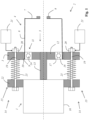
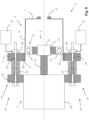
- Fig. 1 shows a first exemplary embodiment of an actuator according to the invention, which has a drive motor 1.
- An exemplary embodiment of a voltage wave transmission 2 according to the invention is connected downstream of the drive motor 1.
- the voltage wave transmission 2 has a circular spline 3, a flexspline 4 and a wave generator 5.
- the flexspline 4 has a tubular, radially flexible sleeve 6, which is connected at one of its ends in a rotationally fixed manner (preferably by being manufactured in one piece) to a radially inwardly directed circular disk 7. On the circular disk 7 there is a fastening flange 8 for coupling a shaft (not shown), for example an output shaft. At the other end, the tubular, radially flexible sleeve 6 has an external toothing 9, which meshes with a circular spline toothing 10 of the circular spline 3 at two opposite points.
- the wave generator 5 has a radially flexible bearing 11, which is designed as a rolling bearing and which has a bearing inner ring 17 and a bearing outer ring 18 and rolling elements 24.
- the wave generator 5 also has a shaping means 12 which is rotatably mounted relative to the flexspline 4 by means of the bearing 11 and which shapes the bearing 11 and the end of the flexspline 4 provided with the external teeth 9 into a shape different from the circular shape and thereby the tooth engagement with the External teeth 9 with the circular spline teeth 10 at two opposite locations (or at three or more locations).
- the shaping means 12 is designed as an oval, in particular elliptical, disk which is connected in a rotationally fixed manner to an output shaft 13 of the drive motor 1.
- the shaping means 12 acts as a gear drive, while the fastening flange 8 acts as an output, with the circular spline 3 (among other functions) having the function of the tension wave gear with regard to the torque occurring during operation (via the linear displacement device 14 described below) on the housing 16 of the Support the drive motor.
- the wave generator 5 is arranged to be infinitely axially adjustable relative to the Flexspline 4.
- the bearing outer ring 18 is axially displaceably mounted on its outer peripheral surface relative to the Flexspline 4.
- the circular spline 3 is connected to the housing 16 of the drive motor 1 via a linear displacement device 14, which has a plurality of spindle drives 15.
- Each spindle drive 15 has a threaded spindle 19 and a spindle nut 20.
- the linear displacement device 14 has several synchronously driven servomotors 21 (and only shown very schematically).
- the drive motor 1 can be axially displaced relative to the flexspline 4 together with the drive shaft 13 and the wave generator 5.
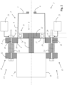
- the wave generator 5 can be axially displaced in the direction of the circular disk 7 by actuating the linear displacement device 14.
- the circular spline 3 and a support flange 22 arranged firmly on the housing 16 of the drive motor 1 approach each other, with springs 23 arranged between the circular spline 3 and the support flange 22 being compressed, which results in Figure 2 is shown.
- part of the wave generator 5 is arranged axially offset from the circular spline toothing 10 and from the external toothing 9 of the flexspline 4; namely the part that is located in the figure between the two dashed lines.
- the bearing outer ring (as the part of the shaft generator that is in direct contact with the Flexspline) together with the other components of the shaft generator is optionally in one of at least two different ones Settings (setting according to Figure 1 and setting accordingly Figure 2 ) adjustable in which the voltage wave gear can be operated.
- FIG. 1 and 2 a cross section through the plane of the vertical axis of the molding body 12 is shown.
- the wall of the tubular, radially flexible sleeve 6 of the Flexspline 4 extends in a wedge shape starting from the circular disk 7.
- the wall of the tubular, radially flexible sleeve 6 of the Flexspline 4 extends in a wedge shape starting from the circular disk 7.
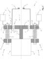
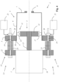
- the Figures 3 and 4 show a second embodiment of an actuator according to the invention, which differs from that in the Figures 1 and 2 illustrated embodiment differs in that the bearing 11 has no bearing outer ring 18. Rather, the bearing 11 in this embodiment has a dual function, namely, on the one hand, the function of supporting the shaping means 12 in a rotatable manner relative to the Flexspline 4, and on the other hand, the function of supporting the shaping means 12 in an axially adjustable manner relative to the Flexspline 4.
- the rolling elements 24 of the bearing 11 are in direct contact with the Flexspline 4 in this exemplary embodiment.
- the rolling elements 24 (as the part of the wave generator that is in direct contact with the flexspline) together with the other components of the wave generator are optionally in one of at least two different settings (setting according to Figure 3 and setting accordingly Figure 4 ) adjustable in which the voltage wave gear can be operated.
- part of the wave generator 5 is arranged axially offset from the circular spline toothing 10 and from the external toothing 9 of the flexspline 4.
- FIGS. 5 and 6 show a third exemplary embodiment of an actuator according to the invention, which has a drive motor 1.
- An exemplary embodiment of a voltage wave transmission 2 according to the invention is connected downstream of the drive motor 1.
- the voltage wave transmission 2 has a circular spline 3, a flexspline 4 and a wave generator 5.
- the flexspline 4 has a tubular, radially flexible sleeve 6, which is connected at one of its ends in a rotationally fixed manner (preferably by being manufactured in one piece) to a radially inwardly directed circular disk 7. On the circular disk 7 there is a fastening flange 8 for coupling a shaft (not shown), for example an output shaft. At the other end, the tubular, radially flexible sleeve 6 has an external toothing 9, which meshes with a circular spline toothing 10 of the circular spline 3 designed as an internal toothing at two opposite points.
- the wave generator 5 has a radially flexible bearing 11, which is designed as a rolling bearing and which has a bearing inner ring 17 and a bearing outer ring 18 and rolling elements 24.
- the wave generator 5 also has a shaping means 12 which is rotatably mounted relative to the flexspline 4 by means of the bearing 11 and which shapes the bearing 11 and the end of the flexspline 4 provided with the external teeth 9 into a shape different from the circular shape and thereby the tooth engagement with the External teeth 9 with the circular spline teeth 10 at two opposite locations.
- the shaping means 12 is designed as an oval, in particular elliptical, body which is connected in a rotationally fixed manner to an output shaft 13 of the drive motor 1.
- the shaping means 12 acts as a gear drive, while the fastening flange 8 acts as an output, with the circular spline 3 (among other functions) having the function of controlling the tension wave gear with regard to the torque that occurs during operation on a higher-level structure (not shown), for example relative to a carrier , in particular a carrier of a chassis or a robot, or a system housing or on the housing 16 or a stator of the drive motor.
- the outer circumference of the shaping means 12 has a plurality of axially offset bearing seats 25, 26 into which the rolling bearing 11 (preferably axially slidingly mounted) can be axially displaced.
- a rotation preventing means may be present which, although it allows an axial displacement of the bearing inner ring 17 relative to the shaping means 12, but prevents rotation of the bearing inner ring 17 relative to the shaping means 12.
- the rotation preventing means can, for example, have a groove which runs in the axial direction in the shaping means 12 and into which a radially inwardly directed projection of the bearing inner ring 17 engages.
- the axial adjustment of the wave generator 5 is effected in that only the radially flexible bearing 11 is adjusted axially, continuously or in steps (preferably by means of a servomotor 21) relative to the flexspline 4 and relative to the shaping means 12, while the shaping means 12 maintains its axial position relative to the Flexspline 4.
- FIG. 5 and 6 a cross section through the plane of the vertical axis of the molding body 12 is shown.
- the runs in this level Wall of the tubular, radially flexible sleeve 6 of the Flexspline 4 spreads apart in a wedge shape starting from the circular disk 7.
- the wall of the tubular, radially flexible sleeve 6 of the Flexspline 4 extends in a wedge shape starting from the circular disk 7.
- the plane of the low axis (not shown) runs perpendicular to the plane of the drawing through the center axis of rotation.
- the bearing outer ring (as the part of the shaft generator that is in direct contact with the Flexspline) together with the other components of the bearing 11 can be optionally set in one of at least two different settings (setting according to Figure 5 and setting accordingly Figure 6 ) adjustable in which the voltage wave gear can be operated.
- the wave generator 5 is arranged axially offset from the circular spline toothing 10 and from the external toothing 9 of the flexspline 4.
- FIGS. 7 and 8th show a fourth exemplary embodiment of an actuator according to the invention, which includes a voltage wave gear according to the invention, in two different settings of the wave generator 5 relative to the flexspline 4.
- the fourth exemplary embodiment essentially corresponds to the first exemplary embodiment, but the shaft generator 5 has a compensating clutch 27, which can be designed, for example, as an Oldham clutch or a claw clutch.
- the compensating coupling can in particular be designed to compensate for alignment and/or angular errors, in particular of the output shaft 13 relative to the shaft generator 5 and/or relative to the radially flexible sleeve 6 and/or relative to the circular spline 3.
Landscapes
- Engineering & Computer Science (AREA)
- General Engineering & Computer Science (AREA)
- Mechanical Engineering (AREA)
- Robotics (AREA)
- Retarders (AREA)
Applications Claiming Priority (1)
| Application Number | Priority Date | Filing Date | Title |
|---|---|---|---|
| LU502059 | 2022-05-10 |
Publications (1)
| Publication Number | Publication Date |
|---|---|
| EP4276332A1 true EP4276332A1 (fr) | 2023-11-15 |
Family
ID=82446668
Family Applications (1)
| Application Number | Title | Priority Date | Filing Date |
|---|---|---|---|
| EP23172033.5A Pending EP4276332A1 (fr) | 2022-05-10 | 2023-05-08 | Engrenage à onde de déformation |
Country Status (1)
| Country | Link |
|---|---|
| EP (1) | EP4276332A1 (fr) |
Cited By (3)
| Publication number | Priority date | Publication date | Assignee | Title |
|---|---|---|---|---|
| EP4621265A1 (fr) | 2024-03-21 | 2025-09-24 | Ovalo GmbH | Transmission |
| EP4726237A1 (fr) | 2024-10-11 | 2026-04-15 | Ovalo GmbH | Transmission à onde de déformation |
| DE102024129548A1 (de) | 2024-10-11 | 2026-04-16 | Ovalo Gmbh | Spannungswellengetriebe |
Citations (10)
| Publication number | Priority date | Publication date | Assignee | Title |
|---|---|---|---|---|
| GB1204146A (en) * | 1967-11-23 | 1970-09-03 | Usm Corp | Improvements in or relating to rotary transmission mechanisms |
| US6050155A (en) | 1999-02-03 | 2000-04-18 | Harmonic Drive Technologies | Harmonic drive flexspline with integral flange support |
| DE102007009868A1 (de) * | 2006-02-28 | 2007-08-30 | Harmonic Drive Systems Inc. | Verfahren zum Reduzieren von antriebsseitigem Haltedrehmoment einer Wellgetriebeeinrichtung und Rotationsstellglied |
| DE102007035038A1 (de) * | 2006-07-27 | 2008-01-31 | Harmonic Drive Systems Inc. | Automatische Drehmoment-Umschaltvorrichtung |
| WO2011029472A1 (fr) * | 2009-09-09 | 2011-03-17 | Abb Research Ltd | Ensemble d'entraînement, robot industriel, bras de robot et joint de robot |
| DE112011105253T5 (de) | 2011-05-16 | 2014-02-13 | Harmonic Drive Systems Inc. | Einheitstyp-Wellgetriebe |
| DE112013004710T5 (de) | 2013-07-01 | 2015-06-11 | Harmonic Drive Systems Inc. | Hohles Verformungswellgetriebe |
| US20150184700A1 (en) | 2013-11-21 | 2015-07-02 | Hamilton Sundstrand Corporation | Drive assembly with selective disconnect |
| DE102019102264A1 (de) * | 2019-01-30 | 2020-07-30 | Schaeffler Technologies AG & Co. KG | Wellgetriebe und Verfahren zur Montage eines Nockenwellenverstellers |
| WO2022062620A1 (fr) * | 2020-09-28 | 2022-03-31 | 珠海格力电器股份有限公司 | Dispositif de compensation de rigidité, réducteur d'harmonique et robot |
-
2023
- 2023-05-08 EP EP23172033.5A patent/EP4276332A1/fr active Pending
Patent Citations (10)
| Publication number | Priority date | Publication date | Assignee | Title |
|---|---|---|---|---|
| GB1204146A (en) * | 1967-11-23 | 1970-09-03 | Usm Corp | Improvements in or relating to rotary transmission mechanisms |
| US6050155A (en) | 1999-02-03 | 2000-04-18 | Harmonic Drive Technologies | Harmonic drive flexspline with integral flange support |
| DE102007009868A1 (de) * | 2006-02-28 | 2007-08-30 | Harmonic Drive Systems Inc. | Verfahren zum Reduzieren von antriebsseitigem Haltedrehmoment einer Wellgetriebeeinrichtung und Rotationsstellglied |
| DE102007035038A1 (de) * | 2006-07-27 | 2008-01-31 | Harmonic Drive Systems Inc. | Automatische Drehmoment-Umschaltvorrichtung |
| WO2011029472A1 (fr) * | 2009-09-09 | 2011-03-17 | Abb Research Ltd | Ensemble d'entraînement, robot industriel, bras de robot et joint de robot |
| DE112011105253T5 (de) | 2011-05-16 | 2014-02-13 | Harmonic Drive Systems Inc. | Einheitstyp-Wellgetriebe |
| DE112013004710T5 (de) | 2013-07-01 | 2015-06-11 | Harmonic Drive Systems Inc. | Hohles Verformungswellgetriebe |
| US20150184700A1 (en) | 2013-11-21 | 2015-07-02 | Hamilton Sundstrand Corporation | Drive assembly with selective disconnect |
| DE102019102264A1 (de) * | 2019-01-30 | 2020-07-30 | Schaeffler Technologies AG & Co. KG | Wellgetriebe und Verfahren zur Montage eines Nockenwellenverstellers |
| WO2022062620A1 (fr) * | 2020-09-28 | 2022-03-31 | 珠海格力电器股份有限公司 | Dispositif de compensation de rigidité, réducteur d'harmonique et robot |
Cited By (3)
| Publication number | Priority date | Publication date | Assignee | Title |
|---|---|---|---|---|
| EP4621265A1 (fr) | 2024-03-21 | 2025-09-24 | Ovalo GmbH | Transmission |
| EP4726237A1 (fr) | 2024-10-11 | 2026-04-15 | Ovalo GmbH | Transmission à onde de déformation |
| DE102024129548A1 (de) | 2024-10-11 | 2026-04-16 | Ovalo Gmbh | Spannungswellengetriebe |
Similar Documents
| Publication | Publication Date | Title |
|---|---|---|
| EP2424765B1 (fr) | Vanne de direction à train épicycloïdal | |
| EP4276332A1 (fr) | Engrenage à onde de déformation | |
| EP3322632B1 (fr) | Actionneur à rétroaction pour un dispositif de direction | |
| DE3787552T2 (de) | Zusatzgetriebe für Kraftfahrzeuge. | |
| EP2236324A2 (fr) | Dispositif de réglage en hauteur pour suspensions de roues de véhicules automobiles | |
| EP2334949A1 (fr) | Boîtier de différentiel à excentrique | |
| EP2208661A1 (fr) | Entraînement de rangement pour remorques de véhicules | |
| EP3504102B1 (fr) | Volant de direction pour actionner un mouvement de braquage d'un véhicule | |
| EP3870495A1 (fr) | Colonne de direction pour un véhicule automobile | |
| DE102021213456A1 (de) | Spindelantrieb sowie Verfahren zum Betreiben eines solchen | |
| EP2731850B1 (fr) | Pignon de direction pour un système de direction et procédé pour sa fabrication | |
| EP3882478B1 (fr) | Chaine cinématique avec un accouplement extensible entre un arbre moteur et un arbre d'entrée d'une boîte de vitesses | |
| DE19518196A1 (de) | Hilfskraftlenkung für Kraftfahrzeuge | |
| DE102011089054A1 (de) | Schaltvorrichtung | |
| DE102004018797A1 (de) | Lenkvorrichtung für Fahrzeuge | |
| DE102022111705A1 (de) | Spannungswellengetriebe | |
| DE102022120890A1 (de) | Spindelysystem, linearaktuator und möbelstück | |
| DE69704202T2 (de) | Neigungsverstellungsmechanismus für einen Sitz | |
| DE3500992A1 (de) | Mehrganggetriebe fuer ein fahrzeug | |
| WO2003087632A2 (fr) | Unite d'actionnement destinee a une boite de vitesses et arbre de commande | |
| EP1518065B1 (fr) | Dispositif de changement de vitesse | |
| DE102019127865A1 (de) | Planetenwälzgetriebe und Verfahren zur Herstellung eines Planetenwälzgetriebes | |
| DE102007026107A1 (de) | Kraftfahrzeugsitzverstellantrieb | |
| WO2018219691A1 (fr) | Entraînement de réglage comprenant un mécanisme différentiel servant à régler une course de réglage linéaire pouvant être prédéfinie | |
| DE102019205944B4 (de) | Getriebeeinheit für eine Kraftfahrzeuglenkung |
Legal Events
| Date | Code | Title | Description |
|---|---|---|---|
| PUAI | Public reference made under article 153(3) epc to a published international application that has entered the european phase |
Free format text: ORIGINAL CODE: 0009012 |
|
| STAA | Information on the status of an ep patent application or granted ep patent |
Free format text: STATUS: THE APPLICATION HAS BEEN PUBLISHED |
|
| AK | Designated contracting states |
Kind code of ref document: A1 Designated state(s): AL AT BE BG CH CY CZ DE DK EE ES FI FR GB GR HR HU IE IS IT LI LT LU LV MC ME MK MT NL NO PL PT RO RS SE SI SK SM TR |
|
| STAA | Information on the status of an ep patent application or granted ep patent |
Free format text: STATUS: REQUEST FOR EXAMINATION WAS MADE |
|
| 17P | Request for examination filed |
Effective date: 20240515 |
|
| RBV | Designated contracting states (corrected) |
Designated state(s): AL AT BE BG CH CY CZ DE DK EE ES FI FR GB GR HR HU IE IS IT LI LT LU LV MC ME MK MT NL NO PL PT RO RS SE SI SK SM TR |
|
| STAA | Information on the status of an ep patent application or granted ep patent |
Free format text: STATUS: EXAMINATION IS IN PROGRESS |
|
| 17Q | First examination report despatched |
Effective date: 20250707 |