EP4276359A1 - Buse de carburant à passages d'air multiples - Google Patents
Buse de carburant à passages d'air multiples Download PDFInfo
- Publication number
- EP4276359A1 EP4276359A1 EP23152425.7A EP23152425A EP4276359A1 EP 4276359 A1 EP4276359 A1 EP 4276359A1 EP 23152425 A EP23152425 A EP 23152425A EP 4276359 A1 EP4276359 A1 EP 4276359A1
- Authority
- EP
- European Patent Office
- Prior art keywords
- fuel
- air
- fuel nozzle
- combustion
- air passages
- Prior art date
- Legal status (The legal status is an assumption and is not a legal conclusion. Google has not performed a legal analysis and makes no representation as to the accuracy of the status listed.)
- Granted
Links
Images


Classifications
-
- F—MECHANICAL ENGINEERING; LIGHTING; HEATING; WEAPONS; BLASTING
- F23—COMBUSTION APPARATUS; COMBUSTION PROCESSES
- F23R—GENERATING COMBUSTION PRODUCTS OF HIGH PRESSURE OR HIGH VELOCITY, e.g. GAS-TURBINE COMBUSTION CHAMBERS
- F23R3/00—Continuous combustion chambers using liquid or gaseous fuel
- F23R3/28—Continuous combustion chambers using liquid or gaseous fuel characterised by the fuel supply
-
- F—MECHANICAL ENGINEERING; LIGHTING; HEATING; WEAPONS; BLASTING
- F23—COMBUSTION APPARATUS; COMBUSTION PROCESSES
- F23R—GENERATING COMBUSTION PRODUCTS OF HIGH PRESSURE OR HIGH VELOCITY, e.g. GAS-TURBINE COMBUSTION CHAMBERS
- F23R3/00—Continuous combustion chambers using liquid or gaseous fuel
- F23R3/28—Continuous combustion chambers using liquid or gaseous fuel characterised by the fuel supply
- F23R3/34—Feeding into different combustion zones
- F23R3/346—Feeding into different combustion zones for staged combustion
-
- F—MECHANICAL ENGINEERING; LIGHTING; HEATING; WEAPONS; BLASTING
- F23—COMBUSTION APPARATUS; COMBUSTION PROCESSES
- F23R—GENERATING COMBUSTION PRODUCTS OF HIGH PRESSURE OR HIGH VELOCITY, e.g. GAS-TURBINE COMBUSTION CHAMBERS
- F23R3/00—Continuous combustion chambers using liquid or gaseous fuel
- F23R3/28—Continuous combustion chambers using liquid or gaseous fuel characterised by the fuel supply
- F23R3/286—Continuous combustion chambers using liquid or gaseous fuel characterised by the fuel supply having fuel-air premixing devices
-
- F—MECHANICAL ENGINEERING; LIGHTING; HEATING; WEAPONS; BLASTING
- F23—COMBUSTION APPARATUS; COMBUSTION PROCESSES
- F23R—GENERATING COMBUSTION PRODUCTS OF HIGH PRESSURE OR HIGH VELOCITY, e.g. GAS-TURBINE COMBUSTION CHAMBERS
- F23R3/00—Continuous combustion chambers using liquid or gaseous fuel
- F23R3/42—Continuous combustion chambers using liquid or gaseous fuel characterised by the arrangement or form of the flame tubes or combustion chambers
- F23R3/58—Cyclone or vortex type combustion chambers
Definitions
- the invention generally relates to a fuel nozzle, which is intentionally used at a combustion arrangement of a gas turbine as a second (or later) stage fuel injector downstream to a primary burner. Thereby the fuel nozzle enables the introduction of fuel and air into a secondary combustion zone.
- Combustion arrangements of gas turbines comprise a combustion chamber with at least one primary burner arranged at the head end of the combustion chamber. This defines a primary combustion zone adjacent to the burner within the combustion chamber.
- a transition is arranged downstream the combustion chamber guiding the combustion gases from the combustion chamber to an expansion turbine.
- combustion arrangements comprise downstream to the primary combustion zone a further secondary combustion zone.
- This is enabled by the arrangement of secondary stage fuel nozzles within the transition. Examples of these fuel nozzles are presented in EP 3479025 B1 , EP 3472518 B1 and EP 3436746 B1 . All these kind of fuel nozzles are having one central air passage. The air is guided from outside of the transition through the fuel nozzle into the transition. At the cold side of the fuel nozzle in general a fuel distribution is attached injecting fuel into the air passage.
- the generic fuel nozzle is intentionally used in a combustion arrangement. First, it is not relevant which kind of combustion arrangement is given and for which purpose the combustion arrangement is used.
- the implementation of the fuel nozzle is in particular useful at a combustion arrangement of a gas turbine.
- the gas turbine comprises as usual a compressor, a combustion arrangement and an expansion turbine.
- the generic combustion arrangement comprises at least one combustion chamber with at least one primary burner arranged at the head end of the combustion chamber. This defines a primary combustion zone within the combustion chamber adjacent to the primary burner.
- the advantage embodiment of the combustion arrangement makes use of at least one fuel nozzle as a second stage fuel injector arranged downstream of the primary combustion zone. Thereby the fuel nozzle enables a second stage combustion with a secondary combustion zone.
- the combustion arrangement comprises further a transition, which is arranged downstream of the combustion chamber.
- the at least one fuel nozzle is arranged within the transition.
- fuel nozzles are arranged circumferentially distributed.
- the fuel nozzle comprises a main body extending from a cold side to an opposite hot side.
- the hot side is located at the combustion arrangement towards the combustion zone inside the combustion arrangement.
- the opposite cold side is facing away from the combustion zone and is located outside the combustion arrangement.
- a generic fuel nozzle comprises an air passage. Instead of a single air passage the solution makes use of a bunch of air passages arranged next to each other and enabling the stream of air from the cold side to the hot side. Here, it is required to implement at least five air passages. It is advantage if the fuel nozzle comprises at least ten air passages arranged next to each other.
- the air passages cross the fuel distribution chamber, thereby defining a passage wall dividing the air passage from the fuel distribution chamber.
- each of the air passage has a surrounding passage wall.
- air passages esp. at the outer side are only partly crossing the fuel distribution chamber and the passage wall only extends partly in circumferential direction (related to the respective air passage).
- the injection of fuel into the air passages is enabled by the arrangement of fuel holes into the passage walls.
- a fuel hole is arranged within each passage wall. But at least half of the existing air passages needs to comprise at least one fuel hole inside the passage wall.
- a fuel hole is arranged within each of the passage walls.
- the mixing of the fuel within the air is improved with the bunch of air passages. This leads further to an improved combustion within the combustion arrangement. As result it is further possible to achieve reduced NOx emission compared to a combustion arrangement using a generic fuel nozzle.
- the distance between the separate air passages is reduced to enable a joint flow of the air passing the air passages without adverse recirculation at the hot side between the air passages.
- the single air passages follow a bend or inclined curve towards a center axis of the fuel nozzle on their way from the cold side towards the hot side.
- the center axis is already within an air passage in the center of the fuel nozzle and has therefore preferred a straight course.
- the air passages having a greater distance to the center axis at the cold side needs to be bended/inclined more than those closer to the center axis.
- the center axis is extending from the cold side to the hot side in the middle of the fuel nozzle and/or in the middle of the bunch of air passages.
- the air passages are shaped and arranged with their ends facing the hot side according to a honeycomb pattern. It is not required, that the end of each single air passage facing the hot side is exactly shaped as regular hexagon. Relevant is an arrangement of the air passages with their ends in a pattern close to each other with a minimum remaining space between adjacent air passages.
- a further improvement of the mixing of air and fuel could be achieved with the advantage arrangement of turbulators within the air passages.
- a preferred design has a triangular shape with a tip extending into the air passage at the end of the turbulator facing the hot side.
- each of the air passages comprises one turbulator.
- the ends of the air passages facing the hot side is shaped with a honeycomb pattern and that at the cold side the air passages are arranged with some more space with a for example circular shape it is further advantage to arrange the turbulator close to the cold side.
- the turbulators and the fuel holes are located at the same circumferential position within/at the respective air passage.
- the distance from the turbulator to the fuel hole should not extend the height of the respective turbulator.
- the height is defined as dimension of the turbulator from the passage wall extending into the air passage. It is in particular advantageous if the distance between the turbulator and the respective fuel hole is less than 0,5 times the height of the turbulator.
- the fuel nozzle comprises further an air chamber arranged within the main body.
- the streams form the single air passages should pass the air chamber into the combustion zone. Therefore, the air chamber is arranged following to the ends of the air passages facing the hot side. Next the air chamber is open to the hot side.
- This solution is further beneficial due to the fact, that the cross section of the air chamber could be chosen equal to the sum of the cross sections of the single air passages. Without dividing walls, as given at the single air passages, the overall size cross to the center axis could be reduced to the minimum needs.
- the air channel has in a cross section a shape which is slanted relative to the center axis of the fuel nozzle respectively the bunch of air passages pointing towards the hot side. This leads to a similar velocity of the annular stream of cooling air as the stream of mixed air and fuel from the air passages crossing the air chamber.
- At least one air inlet at the outer side of the main body which is connected with the air channel.
- Preferably a few air inlets are arranged at the outer side of the main body in connection with the air channel.
- the fuel nozzle comprises a fuel connection arranged at the main body at the side facing the cold side.
- the inventive fuel nozzle enables an inventive combustion arrangement.
- the generic combustion arrangement comprises a combustion chamber with at least one burner arranged at the upstream end of the combustion chamber. This defines a primary combustion zone at the outlet of the burner within the combustion chamber.
- At least one fuel nozzle is arranged downstream of the primary combustion zone.
- the fuel nozzle enables a secondary combustion zone.
- the inventive solution makes use of an inventive fuel nozzle.
- a transition is arranged to guide the hot combustion gases further downstream of the combustion chamber.
- the fuel nozzle is preferably located at the transition.
- the combustion arrangement preferably comprises at least four fuel nozzles which are distributed in circumferential direction at the combustion chamber or the transition.
- the following figures shows an exemplary combustion arrangement and an example for an inventive fuel nozzle.
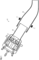
- FIG. 1 an exemplary embodiment of an inventive combustion arrangement 01 is shown.
- This comprises a combustion chamber 03 with a burner 02 arranged at the upstream end of the combustion chamber 032.
- this leads to a primary combustion zone within the combustion chamber 03 next to the burner 02.
- Downstream of the combustion chamber 03 a transition 04 is arranged to guide the hot combustion gases.
- a number of fuel nozzles 11 are arranged, which enable a further combustion of fuel in a secondary combustion zone within the transition.
- FIG. 2 an exemplary embodiment of an inventive fuel nozzle 11 is shown in a longitudinal section. Used at the combustion arrangement the upper side is the cold side 08 at the fuel nozzle 11 facing away from the secondary combustion zone. The lower side in the figure is oriented towards the secondary combustion zone and is therefore the hot side 09.
- the fuel nozzle 11 comprises a main body 12 with a bunch of air passages 14 extending from the cold side 08 towards the hot side 09.
- the air passages 14 opens into an air chamber 13 arranged in the main body 12 between the air passages 14 and the hot side 09.
- the single air passages 14 have a curved course from the cold side 08 up to the air chamber 13, wherein the central air passage 14 goes straight along a centerline of the fuel nozzle 12, wherein those with a bigger distance to the centerline are more curved towards the center.
- each of the air passages 14 changes from the cold side 08 towards the hot side 09.
- the air passages 14 have a circular cross section. This could be seen best in Fig. 3 .
- the air passages 14 have a hexagonally cross section and are therefore arranged similar to a honeycomb (not shown here).
- FIG. 2 Further shown in the Fig. 2 is the arrangement of a fuel distribution chamber 15 close to the cold side 08 within the main body 12.
- the air passages 14 cross the fuel distribution chamber 15 and accordingly each air passage 14 is separated from the fuel distribution chamber 15 with a respective passage wall 17. This could also be seen best in Fig. 4 .
- a fuel pipe 21 is attached to the main body 12.
- one fuel hole 18 is arranged.
- the position in circumferential direction in respect to the respective air passage 14 of these fuel holes 18 differ between the different air passages 14 to avoid an identical flow through all the air passages 14.
- a turbulator 19 is arranged at the passage wall 17 extending into the respective air passage 14. Thereby the mixing of the fuel into the air is enhanced.
- an annular air channel 16 surrounding the air chamber 13 is arranged.
- This air channel 16 opens with a gap into the air chamber 13 close to the hot side 09.
- an air stream is achieved shielding the air-fuel stream from the air passages 14.
Landscapes
- Engineering & Computer Science (AREA)
- Chemical & Material Sciences (AREA)
- Combustion & Propulsion (AREA)
- Mechanical Engineering (AREA)
- General Engineering & Computer Science (AREA)
- Spray-Type Burners (AREA)
Applications Claiming Priority (1)
| Application Number | Priority Date | Filing Date | Title |
|---|---|---|---|
| EP22172962.7A EP4276358A1 (fr) | 2022-05-12 | 2022-05-12 | Buse de combustible dotée de passages d'air multiples |
Publications (3)
| Publication Number | Publication Date |
|---|---|
| EP4276359A1 true EP4276359A1 (fr) | 2023-11-15 |
| EP4276359C0 EP4276359C0 (fr) | 2025-01-01 |
| EP4276359B1 EP4276359B1 (fr) | 2025-01-01 |
Family
ID=81648342
Family Applications (2)
| Application Number | Title | Priority Date | Filing Date |
|---|---|---|---|
| EP22172962.7A Withdrawn EP4276358A1 (fr) | 2022-05-12 | 2022-05-12 | Buse de combustible dotée de passages d'air multiples |
| EP23152425.7A Active EP4276359B1 (fr) | 2022-05-12 | 2023-01-19 | Buse de carburant à passages d'air multiples |
Family Applications Before (1)
| Application Number | Title | Priority Date | Filing Date |
|---|---|---|---|
| EP22172962.7A Withdrawn EP4276358A1 (fr) | 2022-05-12 | 2022-05-12 | Buse de combustible dotée de passages d'air multiples |
Country Status (3)
| Country | Link |
|---|---|
| US (1) | US12072102B2 (fr) |
| EP (2) | EP4276358A1 (fr) |
| CN (1) | CN117053232B (fr) |
Families Citing this family (3)
| Publication number | Priority date | Publication date | Assignee | Title |
|---|---|---|---|---|
| US12188658B1 (en) | 2023-07-07 | 2025-01-07 | Ge Infrastructure Technology Llc | Fuel injection assembly for a combustor |
| US20250362020A1 (en) * | 2024-05-22 | 2025-11-27 | General Electric Company | Gas turbine engine and fuel nozzle assembly therefor |
| US12553610B1 (en) | 2024-12-04 | 2026-02-17 | General Electric Company | Gas turbine engine including a fuel nozzle having vortex generators |
Citations (10)
| Publication number | Priority date | Publication date | Assignee | Title |
|---|---|---|---|---|
| US20060156730A1 (en) * | 2005-01-17 | 2006-07-20 | General Electric Company | Multiple venturi tube gas fuel injector for a combustor |
| US20100008179A1 (en) * | 2008-07-09 | 2010-01-14 | General Electric Company | Pre-mixing apparatus for a turbine engine |
| US20110289928A1 (en) * | 2010-05-25 | 2011-12-01 | Fox Timothy A | Air/fuel supply system for use in a gas turbine engine |
| US20150285501A1 (en) * | 2014-04-08 | 2015-10-08 | General Electric Company | System for cooling a fuel injector extending into a combustion gas flow field and method for manufacture |
| US20170370589A1 (en) * | 2016-06-22 | 2017-12-28 | General Electric Company | Multi-tube late lean injector |
| WO2019020350A1 (fr) * | 2017-07-27 | 2019-01-31 | Siemens Aktiengesellschaft | Brûleur de turbine à gaz à jets de flamme prémélangés |
| EP3436746B1 (fr) | 2016-03-30 | 2020-01-22 | Siemens Energy, Inc. | Ensemble injecteur et agencement de conduits comportant de tels ensembles injecteurs dans un système de combustion pour turbine à gaz |
| EP3472518B1 (fr) | 2016-09-27 | 2020-11-18 | Siemens Aktiengesellschaft | Combustion par étage axial de mazout pour améliorer les performances d'une chambre de combustion de turbine |
| US20200378604A1 (en) | 2019-05-30 | 2020-12-03 | Doosan Heavy Industries & Construction Co., Ltd. | Combustor with axial fuel staging system and gas turbine having the same |
| EP3479025B1 (fr) | 2016-08-03 | 2021-11-03 | Siemens Energy Global GmbH & Co. KG | Ensembles injecteurs conçus pour former un flux de protection d'air injecté dans un étage de combustion dans un moteur de turbine à gaz |
Family Cites Families (4)
| Publication number | Priority date | Publication date | Assignee | Title |
|---|---|---|---|---|
| US20100170253A1 (en) * | 2009-01-07 | 2010-07-08 | General Electric Company | Method and apparatus for fuel injection in a turbine engine |
| US8959921B2 (en) * | 2010-07-13 | 2015-02-24 | General Electric Company | Flame tolerant secondary fuel nozzle |
| RU2560099C2 (ru) * | 2011-01-31 | 2015-08-20 | Дженерал Электрик Компани | Топливное сопло (варианты) |
| US8720204B2 (en) * | 2011-02-09 | 2014-05-13 | Siemens Energy, Inc. | Resonator system with enhanced combustor liner cooling |
-
2022
- 2022-05-12 EP EP22172962.7A patent/EP4276358A1/fr not_active Withdrawn
-
2023
- 2023-01-19 EP EP23152425.7A patent/EP4276359B1/fr active Active
- 2023-03-30 US US18/128,589 patent/US12072102B2/en active Active
- 2023-05-10 CN CN202310526460.7A patent/CN117053232B/zh active Active
Patent Citations (10)
| Publication number | Priority date | Publication date | Assignee | Title |
|---|---|---|---|---|
| US20060156730A1 (en) * | 2005-01-17 | 2006-07-20 | General Electric Company | Multiple venturi tube gas fuel injector for a combustor |
| US20100008179A1 (en) * | 2008-07-09 | 2010-01-14 | General Electric Company | Pre-mixing apparatus for a turbine engine |
| US20110289928A1 (en) * | 2010-05-25 | 2011-12-01 | Fox Timothy A | Air/fuel supply system for use in a gas turbine engine |
| US20150285501A1 (en) * | 2014-04-08 | 2015-10-08 | General Electric Company | System for cooling a fuel injector extending into a combustion gas flow field and method for manufacture |
| EP3436746B1 (fr) | 2016-03-30 | 2020-01-22 | Siemens Energy, Inc. | Ensemble injecteur et agencement de conduits comportant de tels ensembles injecteurs dans un système de combustion pour turbine à gaz |
| US20170370589A1 (en) * | 2016-06-22 | 2017-12-28 | General Electric Company | Multi-tube late lean injector |
| EP3479025B1 (fr) | 2016-08-03 | 2021-11-03 | Siemens Energy Global GmbH & Co. KG | Ensembles injecteurs conçus pour former un flux de protection d'air injecté dans un étage de combustion dans un moteur de turbine à gaz |
| EP3472518B1 (fr) | 2016-09-27 | 2020-11-18 | Siemens Aktiengesellschaft | Combustion par étage axial de mazout pour améliorer les performances d'une chambre de combustion de turbine |
| WO2019020350A1 (fr) * | 2017-07-27 | 2019-01-31 | Siemens Aktiengesellschaft | Brûleur de turbine à gaz à jets de flamme prémélangés |
| US20200378604A1 (en) | 2019-05-30 | 2020-12-03 | Doosan Heavy Industries & Construction Co., Ltd. | Combustor with axial fuel staging system and gas turbine having the same |
Also Published As
| Publication number | Publication date |
|---|---|
| US20230366552A1 (en) | 2023-11-16 |
| CN117053232B (zh) | 2025-12-23 |
| EP4276359C0 (fr) | 2025-01-01 |
| CN117053232A (zh) | 2023-11-14 |
| EP4276359B1 (fr) | 2025-01-01 |
| EP4276358A1 (fr) | 2023-11-15 |
| US12072102B2 (en) | 2024-08-27 |
Similar Documents
| Publication | Publication Date | Title |
|---|---|---|
| EP4276359B1 (fr) | Buse de carburant à passages d'air multiples | |
| US8316644B2 (en) | Burner having swirler with corrugated downstream wall sections | |
| US10267522B2 (en) | Burner for a combustion chamber of a gas turbine having a mixing and injection device | |
| US8117846B2 (en) | Gas turbine burner and method of mixing fuel and air in a swirling area of a gas turbine burner | |
| US10125993B2 (en) | Burner, gas turbine having such a burner, and fuel nozzle | |
| EP2496883B1 (fr) | Brûleur à prémélange pour chambre de combustion de turbine à gaz | |
| CN103776060B (zh) | 再热喷燃器布置 | |
| EP2169313B1 (fr) | Lance à combustible de turbine à gaz | |
| CN206113000U (zh) | 用于燃气涡轮发动机的燃烧器的燃料喷嘴 | |
| EP2728264A2 (fr) | Ensembles d'injection de carburant dans des moteurs à turbine à combustion | |
| US20140033718A1 (en) | Combustor | |
| EP2618057B1 (fr) | Système de turbine | |
| US10215417B2 (en) | Sequential combustor arrangement with a mixer | |
| JP2016041929A (ja) | 燃焼タービンエンジンの燃料噴射器組立体 | |
| CN118556172A (zh) | 用于燃气涡轮发动机的具有火焰锚定件的多管先导喷射器 | |
| CN102374535A (zh) | 燃料喷射喷嘴主体上的有微坑的/有凹槽的面及相关方法 | |
| CN104564351A (zh) | 冲击冷却组件 | |
| CN107466354A (zh) | 用于燃气涡轮发动机的旋流器、燃烧器和燃烧装置 | |
| US20170089584A1 (en) | Vortex generator, and fuel injection system of a gas turbine with such vortex generator | |
| US20180340689A1 (en) | Low Profile Axially Staged Fuel Injector | |
| EP4187154A1 (fr) | Buse à combustible avec passage d'air à noyau restreint | |
| US20180266678A1 (en) | Staged burner | |
| CN103574638A (zh) | 再热喷燃器和在再热喷燃器内混合燃料/载气流的方法 | |
| JP2010038538A (ja) | 旋回翼および旋回翼装置 | |
| KR102537897B1 (ko) | 연소기의 혼합도 향상을 위한 노즐 구조 |
Legal Events
| Date | Code | Title | Description |
|---|---|---|---|
| PUAI | Public reference made under article 153(3) epc to a published international application that has entered the european phase |
Free format text: ORIGINAL CODE: 0009012 |
|
| STAA | Information on the status of an ep patent application or granted ep patent |
Free format text: STATUS: THE APPLICATION HAS BEEN PUBLISHED |
|
| STAA | Information on the status of an ep patent application or granted ep patent |
Free format text: STATUS: REQUEST FOR EXAMINATION WAS MADE |
|
| AK | Designated contracting states |
Kind code of ref document: A1 Designated state(s): AL AT BE BG CH CY CZ DE DK EE ES FI FR GB GR HR HU IE IS IT LI LT LU LV MC ME MK MT NL NO PL PT RO RS SE SI SK SM TR |
|
| 17P | Request for examination filed |
Effective date: 20231019 |
|
| RBV | Designated contracting states (corrected) |
Designated state(s): AL AT BE BG CH CY CZ DE DK EE ES FI FR GB GR HR HU IE IS IT LI LT LU LV MC ME MK MT NL NO PL PT RO RS SE SI SK SM TR |
|
| GRAP | Despatch of communication of intention to grant a patent |
Free format text: ORIGINAL CODE: EPIDOSNIGR1 |
|
| STAA | Information on the status of an ep patent application or granted ep patent |
Free format text: STATUS: GRANT OF PATENT IS INTENDED |
|
| RIC1 | Information provided on ipc code assigned before grant |
Ipc: F23R 3/28 20060101ALI20240730BHEP Ipc: F23R 3/34 20060101AFI20240730BHEP |
|
| INTG | Intention to grant announced |
Effective date: 20240814 |
|
| GRAS | Grant fee paid |
Free format text: ORIGINAL CODE: EPIDOSNIGR3 |
|
| GRAA | (expected) grant |
Free format text: ORIGINAL CODE: 0009210 |
|
| STAA | Information on the status of an ep patent application or granted ep patent |
Free format text: STATUS: THE PATENT HAS BEEN GRANTED |
|
| AK | Designated contracting states |
Kind code of ref document: B1 Designated state(s): AL AT BE BG CH CY CZ DE DK EE ES FI FR GB GR HR HU IE IS IT LI LT LU LV MC ME MK MT NL NO PL PT RO RS SE SI SK SM TR |
|
| REG | Reference to a national code |
Ref country code: GB Ref legal event code: FG4D |
|
| REG | Reference to a national code |
Ref country code: CH Ref legal event code: EP |
|
| REG | Reference to a national code |
Ref country code: DE Ref legal event code: R096 Ref document number: 602023001516 Country of ref document: DE |
|
| REG | Reference to a national code |
Ref country code: IE Ref legal event code: FG4D |
|
| U01 | Request for unitary effect filed |
Effective date: 20250116 |
|
| U07 | Unitary effect registered |
Designated state(s): AT BE BG DE DK EE FI FR IT LT LU LV MT NL PT RO SE SI Effective date: 20250122 |
|
| U20 | Renewal fee for the european patent with unitary effect paid |
Year of fee payment: 3 Effective date: 20250127 |
|
| PG25 | Lapsed in a contracting state [announced via postgrant information from national office to epo] |
Ref country code: PL Free format text: LAPSE BECAUSE OF FAILURE TO SUBMIT A TRANSLATION OF THE DESCRIPTION OR TO PAY THE FEE WITHIN THE PRESCRIBED TIME-LIMIT Effective date: 20250101 |
|
| PG25 | Lapsed in a contracting state [announced via postgrant information from national office to epo] |
Ref country code: ES Free format text: LAPSE BECAUSE OF FAILURE TO SUBMIT A TRANSLATION OF THE DESCRIPTION OR TO PAY THE FEE WITHIN THE PRESCRIBED TIME-LIMIT Effective date: 20250101 |
|
| PG25 | Lapsed in a contracting state [announced via postgrant information from national office to epo] |
Ref country code: NO Free format text: LAPSE BECAUSE OF FAILURE TO SUBMIT A TRANSLATION OF THE DESCRIPTION OR TO PAY THE FEE WITHIN THE PRESCRIBED TIME-LIMIT Effective date: 20250401 Ref country code: IS Free format text: LAPSE BECAUSE OF FAILURE TO SUBMIT A TRANSLATION OF THE DESCRIPTION OR TO PAY THE FEE WITHIN THE PRESCRIBED TIME-LIMIT Effective date: 20250501 |
|
| PG25 | Lapsed in a contracting state [announced via postgrant information from national office to epo] |
Ref country code: HR Free format text: LAPSE BECAUSE OF FAILURE TO SUBMIT A TRANSLATION OF THE DESCRIPTION OR TO PAY THE FEE WITHIN THE PRESCRIBED TIME-LIMIT Effective date: 20250101 |
|
| PG25 | Lapsed in a contracting state [announced via postgrant information from national office to epo] |
Ref country code: GR Free format text: LAPSE BECAUSE OF FAILURE TO SUBMIT A TRANSLATION OF THE DESCRIPTION OR TO PAY THE FEE WITHIN THE PRESCRIBED TIME-LIMIT Effective date: 20250402 |
|
| PG25 | Lapsed in a contracting state [announced via postgrant information from national office to epo] |
Ref country code: CZ Free format text: LAPSE BECAUSE OF FAILURE TO SUBMIT A TRANSLATION OF THE DESCRIPTION OR TO PAY THE FEE WITHIN THE PRESCRIBED TIME-LIMIT Effective date: 20250101 |
|
| PG25 | Lapsed in a contracting state [announced via postgrant information from national office to epo] |
Ref country code: SM Free format text: LAPSE BECAUSE OF FAILURE TO SUBMIT A TRANSLATION OF THE DESCRIPTION OR TO PAY THE FEE WITHIN THE PRESCRIBED TIME-LIMIT Effective date: 20250101 |
|
| PG25 | Lapsed in a contracting state [announced via postgrant information from national office to epo] |
Ref country code: MC Free format text: LAPSE BECAUSE OF FAILURE TO SUBMIT A TRANSLATION OF THE DESCRIPTION OR TO PAY THE FEE WITHIN THE PRESCRIBED TIME-LIMIT Effective date: 20250101 |
|
| PG25 | Lapsed in a contracting state [announced via postgrant information from national office to epo] |
Ref country code: SK Free format text: LAPSE BECAUSE OF FAILURE TO SUBMIT A TRANSLATION OF THE DESCRIPTION OR TO PAY THE FEE WITHIN THE PRESCRIBED TIME-LIMIT Effective date: 20250101 |
|
| PLBE | No opposition filed within time limit |
Free format text: ORIGINAL CODE: 0009261 |
|
| STAA | Information on the status of an ep patent application or granted ep patent |
Free format text: STATUS: NO OPPOSITION FILED WITHIN TIME LIMIT |
|
| REG | Reference to a national code |
Ref country code: CH Ref legal event code: L10 Free format text: ST27 STATUS EVENT CODE: U-0-0-L10-L00 (AS PROVIDED BY THE NATIONAL OFFICE) Effective date: 20251112 |
|
| 26N | No opposition filed |
Effective date: 20251002 |
|
| PG25 | Lapsed in a contracting state [announced via postgrant information from national office to epo] |
Ref country code: IE Free format text: LAPSE BECAUSE OF NON-PAYMENT OF DUE FEES Effective date: 20250119 |
|
| REG | Reference to a national code |
Ref country code: CH Ref legal event code: U11 Free format text: ST27 STATUS EVENT CODE: U-0-0-U10-U11 (AS PROVIDED BY THE NATIONAL OFFICE) Effective date: 20260201 |
|
| U20 | Renewal fee for the european patent with unitary effect paid |
Year of fee payment: 4 Effective date: 20260126 |
|
| PGFP | Annual fee paid to national office [announced via postgrant information from national office to epo] |
Ref country code: CH Payment date: 20260201 Year of fee payment: 4 |