EP4276404A1 - Nicht-konfokales optisches kohärenztomografiebildgebungssystem mit punktabtastung im fourier-bereich - Google Patents
Nicht-konfokales optisches kohärenztomografiebildgebungssystem mit punktabtastung im fourier-bereich Download PDFInfo
- Publication number
- EP4276404A1 EP4276404A1 EP22173231.6A EP22173231A EP4276404A1 EP 4276404 A1 EP4276404 A1 EP 4276404A1 EP 22173231 A EP22173231 A EP 22173231A EP 4276404 A1 EP4276404 A1 EP 4276404A1
- Authority
- EP
- European Patent Office
- Prior art keywords
- light
- scan
- oct
- oct data
- complex volumetric
- Prior art date
- Legal status (The legal status is an assumption and is not a legal conclusion. Google has not performed a legal analysis and makes no representation as to the accuracy of the status listed.)
- Withdrawn
Links
Images

Classifications
-
- G—PHYSICS
- G01—MEASURING; TESTING
- G01B—MEASURING LENGTH, THICKNESS OR SIMILAR LINEAR DIMENSIONS; MEASURING ANGLES; MEASURING AREAS; MEASURING IRREGULARITIES OF SURFACES OR CONTOURS
- G01B9/00—Measuring instruments characterised by the use of optical techniques
- G01B9/02—Interferometers
- G01B9/02034—Interferometers characterised by particularly shaped beams or wavefronts
-
- G—PHYSICS
- G01—MEASURING; TESTING
- G01B—MEASURING LENGTH, THICKNESS OR SIMILAR LINEAR DIMENSIONS; MEASURING ANGLES; MEASURING AREAS; MEASURING IRREGULARITIES OF SURFACES OR CONTOURS
- G01B9/00—Measuring instruments characterised by the use of optical techniques
- G01B9/02—Interferometers
- G01B9/02041—Interferometers characterised by particular imaging or detection techniques
- G01B9/02043—Imaging of the Fourier or pupil or back focal plane, i.e. angle resolved imaging
-
- A—HUMAN NECESSITIES
- A61—MEDICAL OR VETERINARY SCIENCE; HYGIENE
- A61B—DIAGNOSIS; SURGERY; IDENTIFICATION
- A61B3/00—Apparatus for testing the eyes; Instruments for examining the eyes
- A61B3/10—Objective types, i.e. instruments for examining the eyes independent of the patients' perceptions or reactions
- A61B3/1015—Objective types, i.e. instruments for examining the eyes independent of the patients' perceptions or reactions for wavefront analysis
-
- A—HUMAN NECESSITIES
- A61—MEDICAL OR VETERINARY SCIENCE; HYGIENE
- A61B—DIAGNOSIS; SURGERY; IDENTIFICATION
- A61B3/00—Apparatus for testing the eyes; Instruments for examining the eyes
- A61B3/10—Objective types, i.e. instruments for examining the eyes independent of the patients' perceptions or reactions
- A61B3/102—Objective types, i.e. instruments for examining the eyes independent of the patients' perceptions or reactions for optical coherence tomography [OCT]
-
- A—HUMAN NECESSITIES
- A61—MEDICAL OR VETERINARY SCIENCE; HYGIENE
- A61B—DIAGNOSIS; SURGERY; IDENTIFICATION
- A61B3/00—Apparatus for testing the eyes; Instruments for examining the eyes
- A61B3/10—Objective types, i.e. instruments for examining the eyes independent of the patients' perceptions or reactions
- A61B3/107—Objective types, i.e. instruments for examining the eyes independent of the patients' perceptions or reactions for determining the shape or measuring the curvature of the cornea
-
- A—HUMAN NECESSITIES
- A61—MEDICAL OR VETERINARY SCIENCE; HYGIENE
- A61B—DIAGNOSIS; SURGERY; IDENTIFICATION
- A61B5/00—Measuring for diagnostic purposes; Identification of persons
- A61B5/0059—Measuring for diagnostic purposes; Identification of persons using light, e.g. diagnosis by transillumination, diascopy, fluorescence
- A61B5/0062—Arrangements for scanning
- A61B5/0066—Optical coherence imaging
-
- G—PHYSICS
- G01—MEASURING; TESTING
- G01B—MEASURING LENGTH, THICKNESS OR SIMILAR LINEAR DIMENSIONS; MEASURING ANGLES; MEASURING AREAS; MEASURING IRREGULARITIES OF SURFACES OR CONTOURS
- G01B9/00—Measuring instruments characterised by the use of optical techniques
- G01B9/02—Interferometers
- G01B9/02015—Interferometers characterised by the beam path configuration
-
- G—PHYSICS
- G01—MEASURING; TESTING
- G01B—MEASURING LENGTH, THICKNESS OR SIMILAR LINEAR DIMENSIONS; MEASURING ANGLES; MEASURING AREAS; MEASURING IRREGULARITIES OF SURFACES OR CONTOURS
- G01B9/00—Measuring instruments characterised by the use of optical techniques
- G01B9/02—Interferometers
- G01B9/02041—Interferometers characterised by particular imaging or detection techniques
- G01B9/02044—Imaging in the frequency domain, e.g. by using a spectrometer
-
- G—PHYSICS
- G01—MEASURING; TESTING
- G01B—MEASURING LENGTH, THICKNESS OR SIMILAR LINEAR DIMENSIONS; MEASURING ANGLES; MEASURING AREAS; MEASURING IRREGULARITIES OF SURFACES OR CONTOURS
- G01B9/00—Measuring instruments characterised by the use of optical techniques
- G01B9/02—Interferometers
- G01B9/02055—Reduction or prevention of errors; Testing; Calibration
- G01B9/02075—Reduction or prevention of errors; Testing; Calibration of particular errors
- G01B9/02076—Caused by motion
- G01B9/02077—Caused by motion of the object
-
- G—PHYSICS
- G01—MEASURING; TESTING
- G01B—MEASURING LENGTH, THICKNESS OR SIMILAR LINEAR DIMENSIONS; MEASURING ANGLES; MEASURING AREAS; MEASURING IRREGULARITIES OF SURFACES OR CONTOURS
- G01B9/00—Measuring instruments characterised by the use of optical techniques
- G01B9/02—Interferometers
- G01B9/02083—Interferometers characterised by particular signal processing and presentation
-
- G—PHYSICS
- G01—MEASURING; TESTING
- G01B—MEASURING LENGTH, THICKNESS OR SIMILAR LINEAR DIMENSIONS; MEASURING ANGLES; MEASURING AREAS; MEASURING IRREGULARITIES OF SURFACES OR CONTOURS
- G01B9/00—Measuring instruments characterised by the use of optical techniques
- G01B9/02—Interferometers
- G01B9/0209—Low-coherence interferometers
- G01B9/02091—Tomographic interferometers, e.g. based on optical coherence
-
- G—PHYSICS
- G01—MEASURING; TESTING
- G01J—MEASUREMENT OF INTENSITY, VELOCITY, SPECTRAL CONTENT, POLARISATION, PHASE OR PULSE CHARACTERISTICS OF INFRARED, VISIBLE OR ULTRAVIOLET LIGHT; COLORIMETRY; RADIATION PYROMETRY
- G01J3/00—Spectrometry; Spectrophotometry; Monochromators; Measuring colours
- G01J3/28—Investigating the spectrum
- G01J3/2823—Imaging spectrometer
-
- A—HUMAN NECESSITIES
- A61—MEDICAL OR VETERINARY SCIENCE; HYGIENE
- A61B—DIAGNOSIS; SURGERY; IDENTIFICATION
- A61B3/00—Apparatus for testing the eyes; Instruments for examining the eyes
- A61B3/0016—Operational features thereof
- A61B3/0025—Operational features thereof characterised by electronic signal processing, e.g. eye models
-
- G—PHYSICS
- G01—MEASURING; TESTING
- G01B—MEASURING LENGTH, THICKNESS OR SIMILAR LINEAR DIMENSIONS; MEASURING ANGLES; MEASURING AREAS; MEASURING IRREGULARITIES OF SURFACES OR CONTOURS
- G01B2290/00—Aspects of interferometers not specifically covered by any group under G01B9/02
- G01B2290/65—Spatial scanning object beam
Definitions
- Example aspects herein generally relate to the field of Fourier-domain optical coherence tomography (OCT) systems and, in particular, to point-scan Fourier-domain OCT systems.
- OCT optical coherence tomography
- OCT optical coherence tomography
- OCT imaging systems can be classified as being time-domain OCT (TD-OCT) or Fourier-domain OCT (FD-OCT) (also referred to as frequency-domain OCT), depending on how depth ranging is achieved.
- TD-OCT time-domain OCT
- FD-OCT Fourier-domain OCT
- an optical path length of a reference arm of the imaging system's interferometer is varied in time during the acquisition of a reflectivity profile of the scattering medium being imaged by the OCT imaging system (referred to herein as the "imaging target"), the reflectivity profile being commonly referred to as a "depth scan” or "axial scan” (“A-scan").
- FD-OCT a spectral interferogram resulting from an interference between the reference arm and the sample arm of the interferometer at each A-scan location is Fourier transformed to simultaneously acquire all points along the depth of the A-scan, without requiring any variation in the optical path length of the reference arm.
- FD-OCT can allow much faster imaging than scanning of the sample arm mirror in the interferometer, as all the back reflections from the sample are measured simultaneously.
- Two common types of FD-OCT are spectral-domain OCT (SD-OCT) and swept-source OCT (SS-OCT).
- SD-OCT spectral-domain OCT
- SS-OCT swept-source OCT
- SS-OCT also referred to as time-encoded frequency-domain OCT
- the light source is swept through a range of wavelengths, and the temporal output of the detector is converted to spectral interference.
- OCT imaging systems can also be classified as being point-scan (also known as “point detection” or “scanning point”), line-scan or full-field, depending on how the imaging system is configured to acquire OCT data laterally.
- a point-scan OCT imaging system acquires OCT data by scanning a focused sample beam across the surface of the imaging target, typically along a single line (which may be straight, or alternatively curved so as to define a circle or a spiral, for example) or along a set of (usually substantially parallel) lines on the surface of the imaging target, and acquiring an axial depth profile (A-scan) for each of a plurality of points along the line(s), one single point at a time, to build up OCT data comprising a one- or two-dimensional array of A-scans representing a two-dimensional or three-dimensional (volumetric) reflectance profile of the sample.
- A-scan axial depth profile
- Point-scan OCT systems are usually confocal, meaning that a confocal gate is present in the optical path before the interference light detector of the OCT system. This prevents light from points that are in the focal plane of the OCT scanner but not in the vicinity of its focal point from reaching the detector, thus improving the lateral resolution of the point-scan OCT system.
- Point-scan OCT systems typically employ a single-mode optical fibre to convey both the light going from an OCT light source to the imaging target and the return light coming from the imaging target to the interference light detector, with an end of the single-mode optical fibre core effectively providing both a point light source and a confocal gate.
- the return light arriving at the plane of the confocal gate may have a significant proportion of its intensity distributed outside the confocal gate. This results in a reduced signal-to-noise ratio (SNR) in detection, which consequently lowers detection sensitivity and so reduces the imaging quality of the OCT imaging system.
- SNR signal-to-noise ratio
- AO adaptive optics
- a non-confocal point-scan Fourier-domain optical coherence tomography (FD-OCT) imaging system comprising a scanning system arranged to perform a two-dimensional point scan of a light beam across an imaging target, and collect light scattered by the imaging target during the point scan, and a light detector arranged to generate a detection signal based on an interference light resulting from an interference between a reference light and the light collected by the scanning system during the point scan.
- FD-OCT Fourier-domain optical coherence tomography
- the FD-OCT imaging system further comprises OCT data processing hardware arranged to: generate complex volumetric OCT data of the imaging target based on the detection signal, wherein the complex volumetric OCT data, when processed to generate an enface projection of the complex volumetric OCT data, provides an enface projection having at least one of a defocusing or a distortion therein; and generate corrected complex volumetric OCT data by executing a correction algorithm which uses phase information encoded in the complex volumetric OCT data to correct the complex volumetric OCT data, such that the corrected complex volumetric OCT data, when processed to generate an enface projection of the corrected complex volumetric OCT data, provides an enface projection having less of the at least one of the defocusing or the distortion than the enface projection of the complex volumetric OCT data.
- a computer-implemented method of processing complex volumetric OCT data of an imaging target generated by the non-confocal point-scan Fourier-domain OCT imaging system comprises: a scanning system arranged to perform a two-dimensional point scan of a light beam across the imaging target, and collect light scattered by the imaging target during the point scan; a light detector arranged to generate a detection signal based on an interference light resulting from an interference between a reference light and the light collected by the scanning system during the point scan; and OCT data processing hardware arranged to generate the complex volumetric OCT data based on the detection signal, wherein the complex volumetric OCT data, when processed to generate an enface projection of the complex volumetric OCT data, provides an enface projection having at least one of a defocusing or a distortion therein.
- the method comprises acquiring the complex volumetric OCT data of the imaging target from the OCT data processing hardware, and generating corrected complex volumetric OCT data by executing a correction algorithm which uses phase information encoded in the complex volumetric OCT data to correct the complex volumetric OCT data, such that the corrected complex volumetric OCT data, when processed to generate an enface projection of the corrected complex volumetric OCT data, provides an enface projection having less of the at least one of the defocusing or the distortion than the enface projection of the complex volumetric OCT data.
- a computer program comprising computer-readable instructions which, when executed by a processor, cause the processor to perform the method of the second example aspect herein.
- the computer program may be stored on a non-transitory computer-readable storage medium (such as a computer hard disk or a CD, for example) or carried by a computer-readable signal.
- the non-confocal point-scan FD-OCT imaging system may further comprise a light beam generator comprising a light source, a light source aperture and a first optical system, the light source being arranged to emit light through the first optical system via the light source aperture to generate the light beam, wherein the light detector comprises a detection aperture and a second optical system, the light detector being arranged to detect the interference light propagating through the detection aperture via the second optical system, wherein a size of the detection aperture normalised to a focal length of the second optical system is larger than a size of the light source aperture normalised to a focal length of the first optical system.
- the light source aperture may be provided by an end of a core of a first optical fibre and the detection aperture may be provided by an end of a core of a second optical fibre.
- the first optical fibre may be a single-mode optical fibre, and the second optical fibre may be a multi-mode optical fibre.
- the scanning system may comprise at least one scanning element and at least one curved mirror.
- the scanning system may be arranged to perform the two-dimensional point scan by the at least one scanning element scanning the light beam across the imaging target via the at least one curved mirror.
- the at least one curved mirror may comprise an ellipsoidal mirror.
- the non-confocal point-scan FD-OCT imaging system may be a non-confocal point-scan spectral-domain OCT imaging system, or a non-confocal point-scan swept-source OCT imaging system, for example.
- detection sensitivity of Fourier-domain point-scan OCT imaging systems may be improved by departing from the established practice of making these systems confocal, which is typically achieved by the light scattered by the imaging target being collected through the same aperture as the light for illuminating the imaging target is originally launched, this aperture being an end of an optical fibre core in many common implementations.
- an improvement in detection sensitivity may be achieved by making the point-scan FD-OCT imaging system non-confocal, so that components of the return light from the imaging target, which would be blocked by the confocal gate in a confocal point-scan FD-OCT imaging system, are able to contribute to the interference light that is detected in the non-confocal point-scan FD-OCT imaging system.
- non-confocality can be achieved by making the diameter of an optical fibre, whose end provides the detection aperture, larger than the diameter of another optical fibre, whose end provides the source aperture (via which the imaging target is illuminated).
- digital focusing techniques which have been developed for refocusing images (e.g. enface projections or B-scans) from confocal point-scan FD-OCT imaging systems in order to remove the small degree of defocusing that typically occurs in these systems, can be applied to effectively mitigate the more extensive defocusing that may be observed in images from non-confocal point-scan FD-OCT imaging systems that are not well focused and/or have significant aberration, and therefore reduce or prevent the loss of lateral resolution that would otherwise arise in such systems .
- the inventor has found such digital focusing techniques to be applicable to non-confocal point-scan FD-OCT imaging systems despite certain complications that the loss of confocality introduces, which make this finding surprising.
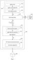
- FIG 1 is a schematic illustration of a non-confocal point-scan FD-OCT imaging system 100 according to example embodiments herein.
- the FD-OCT imaging system 100 comprises a scanning system 110, a light detector 120 and OCT data processing hardware 130.
- the non-confocal point-scan FD-OCT system 100 may, as in the first example embodiment, be a non-confocal point-scan swept-source OCT (SS-OCT) system 300, as shown in the more detailed illustration of the first example embodiment in Figure 4 .
- SS-OCT non-confocal point-scan swept-source OCT
- non-confocal point-scan FD-OCT imaging system 100 need not be provided in this form and may, for example, take the alternative form of a spectral-domain OCT (SD-OCT) system 400, as in the case of the second example embodiment, which is described below with reference to Figure 6 .
- an example embodiment may be provided as any form of non-confocal point-scan FD-OCT imaging system that is capable of generating complex volumetric OCT data, i.e. Fourier transforms of respective spectral interferograms (interference spectra) representing complex A-scan information obtained for each scan location at which an OCT measurement is made during the two-dimensional point scan.
- complex volumetric OCT data encodes phase information from acquired OCT measurements that can be used by a correction algorithm as described herein to digitally refocus OCT image data.
- the scanning system 110 is arranged to perform a two-dimensional point-scan of a light beam L b across an imaging target 140, and collect light L c which has been scattered by the imaging target 140 during the point scan.
- the scanning system 110 is therefore arranged to acquire A-scans at respective scan locations that are distributed two-dimensionally across a surface of the imaging target 140, by sequentially illuminating the scan locations with the light beam L b , one scan location at a time, and collecting at least some of the light L c scattered by the imaging target 140 at each scan location.
- the scanning system 110 may perform the two-dimensional point-scan using any suitable scan pattern known to those versed in the art, for example a unidirectional scan (wherein a set of parallel scan lines are followed in a common direction, along which they extend), a serpentine scan or spiral scan.
- a unidirectional scan wherein a set of parallel scan lines are followed in a common direction, along which they extend
- serpentine scan or spiral scan.
- the FD-OCT imaging system 100 is an ophthalmic FD-OCT imaging system, which is arranged to acquire OCT data from an imaging target 140 in the form of a region of a retina of an eye, although any other part of the eye that can be imaged by OCT, such as a portion of the anterior segment of the eye, may alternatively or additionally form the imaging target 140.
- the imaging target 140 is not, however, limited to a portion of an eye and may alternatively be any tissue (e.g. skin), biological sample or, more generally, any scattering medium whose sub-subsurface structure is to be imaged by OCT.
- the FD-OCT imaging system 100 may further comprise a light beam generator 150 which includes a light source 152, a light source aperture 155, and a first optical system 157.
- the light source 152 is arranged to emit light through first optical system 157, via the light source aperture 155, to generate the light beam L b , such that the shape and size (e.g. diameter, in case of the light source aperture 155 being circular) of the light source aperture 155 defines the cross-sectional shape and size (e.g. diameter) of the light beam L b (i.e. so that these sizes and shapes are the same).
- the light beam generator 150 may comprise further components (not shown in Figure 1 ), such as one or more collimating lenses for collimating light from the light source 152, for example.
- the light detector 120 is arranged to generate a detection signal S d based on an interference light L i resulting from an interference between a reference light L r and the light L c collected by the scanning system 110 during the point scan.
- the reference light and the light collected by the scanning system during the point scan are guided to coincide and interfere with one another, and the resulting interference light L i is directed to and received by light detecting components (not shown) of the light detector 120 via a second optical system 121 and a light detection aperture 122 of the light detector 120.
- the light detector 120 can thus detect the interference light L i propagating through the detection aperture 122 via the second optical system 121.
- the size e.g.
- the aperture size herein refers to a projection area on a plane perpendicular to the direction of light propagation through the aperture.
- the light detector 120 generates the detection signal S d by performing photoelectric conversion of the received interference light L i .
- the light detector 120 may take will depend on the form in which the non-confocal point-scan FD-OCT imaging system 100 is implemented.
- the light detector 120 comprises a spectrometer, which may have a diffraction grating, Fourier transform lend, and a detector array (or a line scan camera).
- the FD-OCT imaging system 100 is implemented as a SS-OCT imaging system, as in the present example embodiment, the light detector 120 may comprise a balanced photodetector set-up comprising two photodetectors (e.g.
- the detection signal S d is then processed by the OCT data processing hardware 130.
- the OCT data processing hardware 130 is arranged to generate complex volumetric OCT data of the imaging target 140, based on the detection signal S d , using well-known data processing techniques.
- the complex volumetric OCT data when processed to generate an enface projection of the complex volumetric OCT data (using any well-known projection technique, such as summed-voxel projection (SVP), or restricted SVP (RSVP), which restricts the SVP to a selected slab of the imaged sample), provides an enface projection having a defocussing (blurring) and/or a distortion in the enface projection image.
- the OCT data includes a component (e.g.
- phase errors which, when the OCT data (or only a subset thereof) is processed to generate an enface projection of the OCT data (using any well-known projection technique, as noted above), provides a defocusing (blurring) and/or a distortion in the enface projection image.
- the defocusing and/or distortion in the enface projection may originate from aberrations in some of the optics within the FD-OCT imaging system 100, for example in one of more curved mirrors that may be provided in the scanning system 110.
- the defocusing and/or distortion may be caused by optical imperfections in the imaging target.
- this defocusing and/or a distortion in the enface projection image is less significant in OCT data generated by such an imaging system, and may be supressed using known numerical refocusing algorithms, for example as disclosed in the article titled " Digital focusing of OCT images based on scalar diffraction theory and information entropy" by G. Liu et al., Biomedical Optic Express, Vol. 3, Issue 11, pp. 2774-2783 , the content of which is hereby incorporated by reference in its entirety.
- the OCT data processing hardware 130 is further arranged to generate corrected complex volumetric OCT data 160 by executing a correction algorithm 132, which processes phase information encoded in the complex volumetric OCT data to correct the complex volumetric OCT data, such that the corrected complex volumetric OCT data 160, when processed to generate an enface projection of the corrected complex volumetric OCT data 160, provides an enface projection having less of the defocusing and/or distortion (i.e. a smaller degree (magnitude) of defocusing and/or distortion) than the enface projection of the complex volumetric OCT data.
- the OCT data processing hardware 130 is further arranged to generate corrected complex volumetric OCT data 160 by executing a correction algorithm 132, which processes phase information encoded in the complex volumetric OCT data to remove or reduce at least some of the aforementioned component (i.e. the source of the defocusing and/or distortion present in the enface projection, which source lies in the complex volumetric OCT data) from the complex volumetric OCT data.
- a correction algorithm 132 processes phase information encoded in the complex volumetric OCT data to remove or reduce at least some of the aforementioned component (i.e. the source of the defocusing and/or distortion present in the enface projection, which source lies in the complex volumetric OCT data) from the complex volumetric OCT data.
- complex data encoding the phase information can be obtained from a discrete Fourier transform (DFT) of the optical spectrum of the interference as measured by the FD-OCT imaging system.
- DFT discrete Fourier transform
- the OCT data processing hardware 130 thus takes the complex volumetric OCT data as an input to the correction algorithm 132, which is run to generate and output corrected complex volumetric OCT data 160, such that an enface projection of the corrected complex volumetric OCT data 160 has less of the defocusing and/or distortion than an enface projection of the input complex volumetric OCT data.
- the corrected complex volumetric OCT data 160 thus has at least some of the above-mentioned component (source) from the complex volumetric OCT data removed or reduced.
- enface projections of the corrected OCT data 160 show a decrease in defocusing and/or aberration-induced distortion, and so an improved lateral resolution relative to enface projections of the complex volumetric OCT data serving as input to the correction algorithm 132.
- the degree of (de)focussing in an enface projection image may be quantified using any one of a number of different ways known to those versed in the art.
- the degree of defocusing may be quantified using a gradient-based, Laplacian-based, wavelet-based, statistics-based or discrete cosine transform-based focus measure operators.
- Various examples of such focus measure operators are provided in the article titled " Analysis of focus measure operators from shape-from-focus" by S. Pertuz et al., published in Pattern Recognition 46 (2013), pages 1415-1432 , the content of which is hereby incorporated by reference in its entirety.
- the correction algorithm 132 may be any numerical refocusing and/or aberration correction algorithm known in the art, which is capable of improving the lateral resolution in the enface projections of the corrected volumetric OCT data 260 by use of complex field information in the volumetric OCT data.
- the correction algorithm 132 applies a phase filter to the complex volumetric OCT data in the Fourier domain, before taking the inverse Fourier transform of the result.
- the phase filter is selected to reduce or remove phase errors which would produce the defocusing/distortion in an enface projection of the complex volumetric OCT data.
- An appropriate phase filter can be derived from a mathematical model of the FD-OCT imaging system.
- the correction algorithm 132 may take the form of the fully automated aberration correction algorithm as described in the article titled " Computational high-resolution optical imaging of the living human retina” by N. D. Shemonski et al., Nature Photonics Vol. 9 (2015): pp. 440-443 , the content of which is hereby incorporated by reference in its entirety (including the supplementary sections therein).
- a Fourier transform of the complex volumetric OCT data is multiplied by a phase filter, before an inverse Fourier transform is applied.
- This phase filter computationally mimics the function of a Shack-Hartmann wavefront sensor, although it may also be adapted to include a defocusing correction, as explained in the aforementioned article by N. D. Shemonski et al.
- a peak detection metric may be applied in conjunction with a guide-star based algorithm to iteratively fine-tune the aberration correction.
- the correction algorithm 132 may take the form of the digital refocusing method in " Digital focusing of OCT images based on scalar diffraction theory and information entropy" by G. Liu et al., Biomed. Opt. Express 3, pp. 2774-2783 (2012 ), the content of which is hereby incorporated by reference in its entirety.
- the described digital refocusing method comprises taking the Fourier transform of the complex volumetric OCT data and rescaling it into linear k-space. This data is then resampled in the axial direction to obtain a sequence of enface frames along the axial direction.
- These enface frames are then digitally refocused onto a new focal plane by performing a search for a focal distance that minimises an entropy function of the image as it varies with each distance (such as a distance corresponding to the image with the minimum Shannon entropy out of a range of refocussed images at differing focal distances).
- a focal distance that minimises an entropy function of the image as it varies with each distance (such as a distance corresponding to the image with the minimum Shannon entropy out of a range of refocussed images at differing focal distances).
- correction algorithm 132 is not limited to the examples set out above.
- the correction algorithm 132 may, for example, take the alternative form of one of the computational aberration correction algorithms, digital refocussing algorithms and interferometric synthetic aperture microscopy algorithms disclosed and/or referenced in " Computational optical coherence tomography [Invited]" by Y. Liu et al., Biomed. Opt. Express 8, pp. 1549-1574 (2017 ), the content of which is hereby incorporated by reference in its entirety.
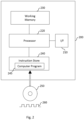
- the OCT data processing hardware 130 may be provided in any suitable form, for example as a programmable signal processing hardware 200 of the kind illustrated schematically in Figure 2 .
- the programmable signal processing apparatus 200 comprises a communication interface (I/F) 210, for receiving the detection signal S d from the light detector 120, and outputting the corrected complex volumetric OCT data 160 and/or a graphical representation thereof (for example, in the form of an enface projection of the corrected complex volumetric OCT data 160) for displaying on a display, such a computer screen or the like.
- the signal processing hardware 200 further comprises a processor (e.g. a Central Processing Unit, CPU, and/or a Graphics Processing Unit, GPU) 220, a working memory 230 (e.g.
- the instruction store 240 may comprise a ROM (e.g. in the form of an electrically erasable programmable read-only memory (EEPROM) or flash memory) which is pre-loaded with the computer-readable instructions.
- EEPROM electrically erasable programmable read-only memory
- the instruction store 240 may comprise a RAM or similar type of memory, and the computer-readable instructions of the computer program 245 can be input thereto from a computer program product, such as a non-transitory, computer-readable storage medium 250 in the form of a CD-ROM, DVDROM, etc. or a computer-readable signal 260 carrying the computer-readable instructions.
- a computer program product such as a non-transitory, computer-readable storage medium 250 in the form of a CD-ROM, DVDROM, etc. or a computer-readable signal 260 carrying the computer-readable instructions.
- the computer program 245 when executed by the processor 220, causes the processor 220 to perform the functions of the OCT data processing hardware 130 as described herein.
- the OCT data processing hardware 130 of the example embodiment may comprise a computer processor 220 and a memory 240 storing computer-readable instructions which, when executed by the computer processor 220, cause the computer processor 220 to generate complex volumetric OCT data of the imaging target based on the detection signal S d from the light detector 120, wherein the complex volumetric OCT data, when processed to generate an enface projection of the complex volumetric OCT data, provides an enface projection having at least one of a defocusing or a distortion in the enface projection.
- the computer-readable instructions when executed by the computer processor 220, cause the computer processor 220 to execute the correction algorithm 132 to remove at least some of the component from the OCT data to produce corrected OCT data 160, as described herein.
- the OCT data processing hardware 130 may alternatively be implemented in non-programmable hardware, such as an ASIC, an FPGA or other integrated circuit dedicated to performing the functions of the OCT data processing hardware 130 described above, or a combination of such non-programmable hardware and programmable hardware as described above with reference to Figure 2 .
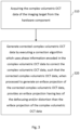
- Figure 3 is a flow diagram illustrating a process (complex volumetric OCT data correction algorithm) by which the OCT data processing hardware 130 of the example embodiment generates the corrected complex volumetric OCT data 160 by executing the correction algorithm 132, which processes phase information encoded in the complex volumetric OCT data to correct the complex volumetric OCT data.
- the OCT data processing hardware 130 acquires the complex volumetric OCT data of the imaging target 140 that has been previously generated thereby, for example by retrieving this data from a memory (e.g. working memory 230 shown in Figure 2 ) of the OCT data processing hardware 130.
- a memory e.g. working memory 230 shown in Figure 2
- the OCT data processing hardware 130 generates the corrected complex volumetric OCT data 160 by executing the correction algorithm 132 described above, thus removing at least some of the component from the complex volumetric OCT data.
- the process of Figure 3 may be performed by OCT data processing hardware 130 implemented in the form of a programmable signal processing hardware 200 as described above with reference to Figure 2 , which operates in accordance with instructions included in a complex volumetric OCT data correction computer program when the computer program is executed by one or more processors.
- This computer program may be stored in a computer program product, such as a non-transitory, computer-readable storage medium in the form of a CD-ROM, DVDROM, etc. or a computer-readable signal carrying the computer-readable instructions.
- the complex volumetric OCT data correction computer program may form part of a computer program which also generates the complex volumetric OCT data of the imaging target 140 based on the detection signal S d , or it may alternatively be a separate program, which may or may not be executed by the same one or more processors that generate the complex volumetric OCT data of the imaging target 140 based on the detection signal S d .
- the first set of one or more processors may acquire the complex volumetric OCT data of the imaging target 140 in process S10 of Figure 3 by receiving this data from the second set of one or more processors via appropriate interfaces between the two sets of processors.
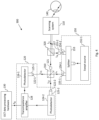
- Figure 4 shows further details of the non-confocal point-scan FD-OCT system of the first example embodiment herein and, in particular, how its component parts may be implemented in case the FD-OCT imaging system 100 is provided in the form of a non-confocal point-scan swept-source OCT (SS-OCT) imaging system 300.
- SS-OCT non-confocal point-scan swept-source OCT
- the light beam generator 150 comprises a swept light source 152-1 in the form of a wavelength-swept (or "tuneable") laser, for example, which is arranged to vary the wavelength of the laser light output thereby across a range of wavelengths over time (preferably linearly), whilst maintaining a narrow instantaneous linewidth.
- the tuneable laser may be of type known to those versed in the art, such as one based on a Fourier-domain mode-locking (FDML) laser with a Fabry-Perot tuneable filter or polygonal scanning mirror, or a microcavity tuneable laser with microelectromechanical systems (MEMS), for example.
- the median frequency of the swept source 152-1 is selected in dependence on the imaging target, and is usually in the near-infrared or infrared part of the spectrum (typically about 1050 nm) in ophthalmic applications, for example.
- the light output by the swept source 152-1 is coupled into an optical fibre and then split into two parts by splitter 153, which may, as in the fibre-optic implementation of the present example embodiment, be a fibre-optic coupler.
- the splitter 153 may alternatively be provided in the form of a beam splitter in an alternative, free-space implementation of the SS-OCT imaging system 300.
- One of the outputs of the splitter 153 follows a first optical path to beam splitter 310 via a first optical fibre 154-1.
- a second output of the splitter 153 follows a second optical path to a beam splitter 320 via a second optical fibre 154-2.
- the first optical fibre 154-2 is thus arranged to guide light from the swept source 152-1 to the scanning system 110 (via the optional beam splitter 320).
- the optical fibres 154-1 and 154-2 are preferably single-mode optical fibres.
- the size of light beam L b and the reference light beam L r may be set by the swept light source 152-1 via a pinhole, window or the like that is a part of the swept light source 152-1.
- the beam splitter 320 reflects light beam L b to the scanning system 110, which is arranged to perform a two-dimensional point-scan of the light beam L b across the imaging target 140, and collect light scattered by the imaging target 140 during the point-scan.
- the scanning system 110 may, as in the present example embodiment, comprise a scanning element and a mirror, wherein the scanning system 110 is arranged to perform the two-dimensional point scan by the scanning element scanning the light beam L b across the imaging target 140 via the mirror.
- a scanning system which is capable of performing a wide-field retinal scan, is described in WO 2014/53824 A1 , the content of which is hereby incorporated by reference in its entirety.
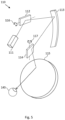
- Components of such a scanning system are shown in Figure 5 and comprise an optical coupler 111, a first scanning element 112, a first curved mirror 113, a second scanning element 114 and a second curved mirror 115.
- the light beam L b enters the scanning system 110 via the optical coupler 111.
- the light beam L b is then reflected, in sequence, by the first scanning element 112, the first curved mirror 113, the second scanning element 114 and the second curved mirror 115, before being incident on the imaging target 140.
- the light L c which has been scattered by the imaging target 140 and collected by the scanning system 110 follows the same optical path through the scanning system 110 as the light beam L b but in reverse order, and exits the scanning system 110 via the optical coupler 111.
- the two-dimensional point scan is performed by the first scanning element 112 rotating around a first axis 116 to scan the light beam L b in a first direction across the imaging target 140, and by the second scanning element 114 rotating around a second axis 117 to scan the light beam L b in a second direction across the imaging target 140 (which may, as in the present example embodiment, be orthogonal to the first direction).
- the rotation of the first scanning element 112 and the second scanning element 114 may be coordinated by a scanning system controller (not shown) such that the light beam L b is scanned across the imaging target 140 in accordance with a predefined scan pattern, as discussed above.
- the first curved mirror 113 is an ellipsoidal mirror (and referred to as a slit mirror), and the second curved mirror 115 is also an ellipsoidal mirror.
- Each of the ellipsoidal mirrors has two focal points.
- the first scanning element 112 is disposed at a first focal point of the first curved mirror 113
- the second scanning element 114 is disposed at a second focal point of the first curved mirror 113.
- the second scanning element 114 is also disposed at a first focal point of the second curved mirror 115
- the imaging target 140 (more specifically, the pupil of the eye in the present example) is disposed at a second focal point of the second curved mirror 115.
- the first scanning element 112 and the second scanning element 114 may, as in the present example embodiment, each be a galvanometer optical scanner (or "galvo"), although another type of scanning element could alternatively be used, such as a MEMS scanning mirror or a resonant scanning mirror, for example.
- galvo galvanometer optical scanner
- the light detector 120 may, as in the present example embodiment, be a balanced detector comprising a first photodetector 124-1 and a second photodetector 124-2, each photodetector being provided in the form of a photodiode in this example (although other forms of photodetector could alternatively be used).
- the light detector 120 also has a transimpedance amplifier 128, which generates a voltage detection signal S d based on a difference between the output photocurrents of the first photodetector 124-1 and second photodetector 124-2.
- the first photodetector 124-1 and the second photodetector 124-2 are arranged to detect interference light L i1 and L i2 , respectively, which result from an interference between the reference light L r and the light L c collected by the scanning system 110 during the point scan, which are superimposed at the beam splitter 310.
- the first photodetector 124-1 receives interference light L i1 via a first light detection aperture 122-1, which is provided in the form of an end of a core of a third optical fibre 125-1
- the second photodetector 124-2 receives interference light L i2 via a second light detection aperture 122-2, which is provided in the form of an end of a core of a fourth optical fibre 125-2.
- the third optical fibre 125-1 and the fourth optical fibre 125-2 may, as in the present example embodiment, both be multi-mode optical fibres and serve to guide light from the detection aperture 122-1 and 122-2, respectively, to the respective photodetectors 124-1 and 124-2. These multi-mode optical fibres may or may not have the same diameter. It should be noted, however, that interference lights L i1 and L i2 need not be guided to photodetectors 124-1 and 124-2 by optical fibres 125-1 and 125-2, and may be collected by the photodetectors 124-1 and 124-2 directly, via respective detection apertures each provided in the form of a pinhole, window or the like that is formed as part of the photodetector.
- Reference light L r interferes with all of the light L c collected by the scanning system 110 during the point scan.
- the light L c includes a degree of defocusing, it may have a larger beam size than the light beam L b generated by the light beam generator 150.
- it may also have a larger beam size than the reference light L r
- the reference light aperture 155-1 and light source aperture 155-2 are the same size in the present example embodiment because the same kind of single mode fibre is used for both the first optical fibre 154-1 and the second optical fibre 154-2.
- the first optical system 121 e.g.
- the reference light beam L r may be enlarged, either by an optical element (e.g. one or more lenses) through which the reference light L r passes or by using a larger reference light aperture 155-1, e.g. by using a larger diameter optical fibre as optical fibre 154-1 than optical fibre 154-2.
- an optical element e.g. one or more lenses
- a balanced photodetector is generally preferable for achieving increased signal-to-noise, it may be replaced with a single photodetector in some example embodiments. In such variants, only one of photodetectors 124-1 and 124-2 as described above would be retained, and the transimpedance amplifier 128 would be omitted, with the single photodetector outputting the detection signal S d to the OCT data processing hardware 130.
- multi-mode optical fibres 125-1 and 125-2 are used to provide respective detection apertures 122-1 and 122-2 and guide the interference lights L i1 and L i2 to the photodetectors 124-1 and 124-2.
- This is a notable difference from conventional confocal point-scan FD-OCT imaging systems, where single-mode optical fibres normally serve these purposes. This is because the sample arm and reference arm of the interferometer in such conventional systems are typically implemented using single-mode optical fibres (as the use of multi-mode optical fibres would introduce modal dispersion into the light beams therein).
- the same single-mode optical fibre is normally used to both transmit the sample beam to the imaging target and transmit light scattered from the imaging target back to the optical coupler that divides the light from the OCT light source to travel along the sample and reference arms of the interferometer. Interference between the scattered light and reference light occurs at the optical coupler.
- an end of a single-mode optical fibre therefore effectively provides both a light source aperture and a detection aperture, which stands in contrast to the asymmetric arrangement in the present example embodiment, where these apertures are provided by ends of different optical fibres.
- optical fibres 125-1 and 125-2 of the light detector 120 serve to guide interference lights L i1 and L i2 to respective photodetectors 124-1 and 124-2, modal dispersion is not a concern (as it is only the photon counts at the photodetectors that matter) so there is no requirement for optical fibres 125-1 and 125-2 to be single-mode fibres.
- Figure 6 is a schematic illustration of a non-confocal point-scan spectral-domain OCT (SD-OCT) imaging system 400 according to a second example embodiment herein.
- SD-OCT spectral-domain OCT
- the SD-OCT imaging system 400 of the present example embodiment comprises a scanning system 110, OCT data processing hardware 130, beam splitters 310 and 320, and a first optical system 121 that are the same as in the first example embodiment. These components, and other components of the SD-OCT imaging system 400 that are labelled with the same reference numerals as in the first example embodiment of Figure 5 , will therefore not be described again.
- the present embodiment differs from the first example embodiment of Figure 5 by the configurations of the light detector 120' and the light beam generator 150', and these will now be described with reference to Figure 6 .
- the light beam generator 150' comprises a broadband light source 152-2, which may, as in the present example embodiment, be a super-luminescent diode.
- the light detector 120' comprises a spectrometer 129, which is arranged to measure the spectrum of the interference signal as a function of wavelength of the light.
- the spectral data may be rescaled and sampled evenly in k-space by the OCT data processing hardware 130, before a Fourier transform is applied to obtain an A-scan.
- Some aspects of the examples presented herein may be provided as a computer program, or software, such as one or more programs having instructions or sequences of instructions, included or stored in an article of manufacture such as a machine-accessible or machine-readable medium, an instruction store, or computer-readable storage device, each of which can be non-transitory, in one example embodiment.
- the program or instructions on the non-transitory machine-accessible medium, machine-readable medium, instruction store, or computer-readable storage device may be used to program a computer system or other electronic device.
- the machine- or computer-readable medium, instruction store, and storage device may include, but are not limited to, floppy diskettes, optical disks, and magneto-optical disks or other types of media/machine-readable medium/instruction store/storage device suitable for storing or transmitting electronic instructions.
- the techniques described herein are not limited to any particular software configuration. They may find applicability in any computing or processing environment.
- computer-readable shall include any medium that is capable of storing, encoding, or transmitting instructions or a sequence of instructions for execution by the machine, computer, or computer processor and that causes the machine/computer/computer processor to perform any one of the methods described herein.
- Such expressions are merely a shorthand way of stating that the execution of the software by a processing system causes the processor to perform an action to produce a result.
- OCT data processing hardware 130 may also be implemented by the preparation of application-specific integrated circuits, field-programmable gate arrays, or by interconnecting an appropriate network of conventional component circuits.
- a computer program product may be provided in the form of a storage medium or media, instruction store(s), or storage device(s), having instructions stored thereon or therein which can be used to control, or cause, a computer or computer processor to perform any of the procedures of the example embodiments described herein.
- the storage medium/instruction store/storage device may include, by example and without limitation, an optical disc, a ROM, a RAM, an EPROM, an EEPROM, a DRAM, a VRAM, a flash memory, a flash card, a magnetic card, an optical card, nanosystems, a molecular memory integrated circuit, a RAID, remote data storage/archive/warehousing, and/or any other type of device suitable for storing instructions and/or data.
- some implementations include software for controlling both the hardware of the system and for enabling the system or microprocessor to interact with a human user or other mechanism utilizing the results of the example embodiments described herein.
- Such software may include without limitation device drivers, operating systems, and user applications.
- Such computer-readable media or storage device(s) further include software for performing example aspects of the invention, as described above.
- a module includes software, although in other example embodiments herein, a module includes hardware, or a combination of hardware and software.
Landscapes
- Health & Medical Sciences (AREA)
- Life Sciences & Earth Sciences (AREA)
- Physics & Mathematics (AREA)
- General Physics & Mathematics (AREA)
- General Health & Medical Sciences (AREA)
- Engineering & Computer Science (AREA)
- Surgery (AREA)
- Public Health (AREA)
- Biophysics (AREA)
- Biomedical Technology (AREA)
- Heart & Thoracic Surgery (AREA)
- Medical Informatics (AREA)
- Molecular Biology (AREA)
- Veterinary Medicine (AREA)
- Animal Behavior & Ethology (AREA)
- Nuclear Medicine, Radiotherapy & Molecular Imaging (AREA)
- Radiology & Medical Imaging (AREA)
- Ophthalmology & Optometry (AREA)
- Spectroscopy & Molecular Physics (AREA)
- Pathology (AREA)
- Signal Processing (AREA)
- Eye Examination Apparatus (AREA)
- Investigating Or Analysing Materials By Optical Means (AREA)
Priority Applications (5)
| Application Number | Priority Date | Filing Date | Title |
|---|---|---|---|
| EP22173231.6A EP4276404A1 (de) | 2022-05-13 | 2022-05-13 | Nicht-konfokales optisches kohärenztomografiebildgebungssystem mit punktabtastung im fourier-bereich |
| EP23169185.8A EP4276405B1 (de) | 2022-05-13 | 2023-04-21 | Nichtkonfokales optisches fourierdomänen-kohärenztomographie-bildgebungssystem mit punktabtastung |
| CN202310536498.2A CN117053676A (zh) | 2022-05-13 | 2023-05-12 | 非共焦点扫描傅里叶域光学相干层析成像系统 |
| US18/197,059 US20230363639A1 (en) | 2022-05-13 | 2023-05-13 | Non-confocal Point-scan Fourier-domain Optical Coherence Tomography Imaging System |
| JP2023079911A JP7476394B2 (ja) | 2022-05-13 | 2023-05-15 | 非共焦点点走査式フーリエ領域光干渉断層計撮像システム |
Applications Claiming Priority (1)
| Application Number | Priority Date | Filing Date | Title |
|---|---|---|---|
| EP22173231.6A EP4276404A1 (de) | 2022-05-13 | 2022-05-13 | Nicht-konfokales optisches kohärenztomografiebildgebungssystem mit punktabtastung im fourier-bereich |
Publications (2)
| Publication Number | Publication Date |
|---|---|
| EP4276404A1 true EP4276404A1 (de) | 2023-11-15 |
| EP4276404A8 EP4276404A8 (de) | 2023-12-27 |
Family
ID=81653668
Family Applications (2)
| Application Number | Title | Priority Date | Filing Date |
|---|---|---|---|
| EP22173231.6A Withdrawn EP4276404A1 (de) | 2022-05-13 | 2022-05-13 | Nicht-konfokales optisches kohärenztomografiebildgebungssystem mit punktabtastung im fourier-bereich |
| EP23169185.8A Active EP4276405B1 (de) | 2022-05-13 | 2023-04-21 | Nichtkonfokales optisches fourierdomänen-kohärenztomographie-bildgebungssystem mit punktabtastung |
Family Applications After (1)
| Application Number | Title | Priority Date | Filing Date |
|---|---|---|---|
| EP23169185.8A Active EP4276405B1 (de) | 2022-05-13 | 2023-04-21 | Nichtkonfokales optisches fourierdomänen-kohärenztomographie-bildgebungssystem mit punktabtastung |
Country Status (4)
| Country | Link |
|---|---|
| US (1) | US20230363639A1 (de) |
| EP (2) | EP4276404A1 (de) |
| JP (1) | JP7476394B2 (de) |
| CN (1) | CN117053676A (de) |
Families Citing this family (3)
| Publication number | Priority date | Publication date | Assignee | Title |
|---|---|---|---|---|
| US12578076B2 (en) | 2023-06-05 | 2026-03-17 | Hamamatsu Photonics K.K. | Dual-output laser-driven light source |
| US12085387B1 (en) * | 2023-09-23 | 2024-09-10 | Hamamatsu Photonics K.K. | Optical coherence tomography system for subsurface inspection |
| CN120525885B (zh) * | 2025-07-24 | 2025-09-19 | 沈阳星光新材料有限公司 | 一种基于图像处理的晶舟缺陷监测方法及系统 |
Citations (2)
| Publication number | Priority date | Publication date | Assignee | Title |
|---|---|---|---|---|
| WO2014053824A1 (en) | 2012-10-01 | 2014-04-10 | Optos Plc | Improvements in or relating to scanning laser ophthalmoscopes |
| US20210038074A1 (en) * | 2018-01-26 | 2021-02-11 | Visotec Gmbh | Full-field oct method and system for generating an imaging of an ocular fundus |
Family Cites Families (7)
| Publication number | Priority date | Publication date | Assignee | Title |
|---|---|---|---|---|
| US20140226158A1 (en) * | 2004-03-06 | 2014-08-14 | Michael Trainer | Methods and apparatus for determining particle characteristics |
| US8275226B2 (en) * | 2008-12-09 | 2012-09-25 | Spectral Applied Research Ltd. | Multi-mode fiber optically coupling a radiation source module to a multi-focal confocal microscope |
| JP5735789B2 (ja) | 2010-12-02 | 2015-06-17 | 株式会社ニデック | 眼底撮影装置 |
| US9636011B2 (en) * | 2014-07-03 | 2017-05-02 | Carl Zeiss Meditec, Inc. | Systems and methods for spectrally dispersed illumination optical coherence tomography |
| JP6606846B2 (ja) | 2015-03-31 | 2019-11-20 | 株式会社ニデック | Oct信号処理装置、およびoct信号処理プログラム |
| JP6603074B2 (ja) * | 2015-08-25 | 2019-11-06 | 株式会社トプコン | 眼底撮影装置 |
| EP4007518A1 (de) * | 2019-08-01 | 2022-06-08 | Carl Zeiss Meditec, Inc. | Ophthalmische abbildung mit k-spiegel-abtastung, effizienter interferometrie und pupillenausrichtung durch räumliche frequenzanalyse |
-
2022
- 2022-05-13 EP EP22173231.6A patent/EP4276404A1/de not_active Withdrawn
-
2023
- 2023-04-21 EP EP23169185.8A patent/EP4276405B1/de active Active
- 2023-05-12 CN CN202310536498.2A patent/CN117053676A/zh active Pending
- 2023-05-13 US US18/197,059 patent/US20230363639A1/en active Pending
- 2023-05-15 JP JP2023079911A patent/JP7476394B2/ja active Active
Patent Citations (2)
| Publication number | Priority date | Publication date | Assignee | Title |
|---|---|---|---|---|
| WO2014053824A1 (en) | 2012-10-01 | 2014-04-10 | Optos Plc | Improvements in or relating to scanning laser ophthalmoscopes |
| US20210038074A1 (en) * | 2018-01-26 | 2021-02-11 | Visotec Gmbh | Full-field oct method and system for generating an imaging of an ocular fundus |
Non-Patent Citations (8)
| Title |
|---|
| DIERCK HILLMANN ET AL: "Aberration-free volumetric high-speed imaging of in vivo retina", ARXIV.ORG, CORNELL UNIVERSITY LIBRARY, 201 OLIN LIBRARY CORNELL UNIVERSITY ITHACA, NY 14853, 12 May 2016 (2016-05-12), XP080701062 * |
| FECHTIG DANIEL J ET AL: "High-speed, digitally refocused retinal imaging with line-field parallel swept source OCT", PROGRESS IN BIOMEDICAL OPTICS AND IMAGING, SPIE - INTERNATIONAL SOCIETY FOR OPTICAL ENGINEERING, BELLINGHAM, WA, US, vol. 9312, 2 March 2015 (2015-03-02), pages 931203 - 931203, XP060046159, ISSN: 1605-7422, ISBN: 978-1-5106-0027-0, DOI: 10.1117/12.2081924 * |
| G. LIU ET AL.: "Digital focusing of OCT images based on scalar diffraction theory and information entropy", BIOMED. OPT. EXPRESS, vol. 3, 2012, pages 2774 - 2783 |
| G. LIU ET AL.: "Digital focusing of OCT images based on scalar diffraction theory and information entropy", BIOMEDICAL OPTIC EXPRESS, vol. 3, pages 2774 - 2783 |
| HELGE SUDKAMP ET AL: "Simple approach for aberration-corrected OCT imaging of the human retina", OPTICS LETTERS, vol. 43, no. 17, 27 August 2018 (2018-08-27), US, pages 4224, XP055571705, ISSN: 0146-9592, DOI: 10.1364/OL.43.004224 * |
| N. D. SHEMONSKI ET AL.: "Computational high-resolution optical imaging of the living human retina", NATURE PHOTONICS, vol. 9, 2015, pages 440 - 443 |
| S. PERTUZ ET AL.: "Analysis of focus measure operators from shape-from-focus", PATTERN RECOGNITION, vol. 46, 2013, pages 1415 - 1432, XP055173399, DOI: 10.1016/j.patcog.2012.11.011 |
| Y. LIU ET AL.: "Computational optical coherence tomography [Invited", BIOMED. OPT. EXPRESS, vol. 8, 2017, pages 1549 - 1574 |
Also Published As
| Publication number | Publication date |
|---|---|
| CN117053676A (zh) | 2023-11-14 |
| JP7476394B2 (ja) | 2024-04-30 |
| JP2023168322A (ja) | 2023-11-24 |
| EP4276405B1 (de) | 2025-08-27 |
| EP4276405A8 (de) | 2024-01-10 |
| EP4276404A8 (de) | 2023-12-27 |
| EP4276405A1 (de) | 2023-11-15 |
| US20230363639A1 (en) | 2023-11-16 |
Similar Documents
| Publication | Publication Date | Title |
|---|---|---|
| EP4276405A1 (de) | Nichtkonfokales optisches kohärenztomographie-bildgebungssystem mit punktscan-fourierdomäne | |
| JP6768747B2 (ja) | Oct光源および走査光学系を使用する2次元の共焦点撮像 | |
| US10571243B2 (en) | Systems and methods for improved OCT measurements | |
| US10602925B2 (en) | Coherence-gated wavefront-sensorless adaptive-optics multi-photon microscopy, and associated systems and methods | |
| US9492078B2 (en) | Extended range imaging | |
| DK2675338T3 (en) | System and method for measuring internal dimensions of an object by means of optical coherence tomography | |
| US10349829B2 (en) | Ophthalmic imaging apparatus | |
| US20220257111A1 (en) | Ophthalmic imaging with k-mirror scanning, efficient interferometry, and pupil alignment through spatial frequency analysis | |
| JP2016220735A (ja) | 光干渉断層計およびその制御方法 | |
| JP7339447B2 (ja) | ライン走査マイクロスコピー用の装置および方法 | |
| Huang et al. | Full-range space-division multiplexing optical coherence tomography angiography | |
| JP7848263B2 (ja) | 切り替え可能マルチ構成oct | |
| EP4439002B1 (de) | Optisches bildgebungssystem für die linienfeldfourierdomänenkohärenztomografie | |
| EP4421440A1 (de) | Techniken mit hoher dispersion für komplexe konjugatauflösung und verwandte aspekte | |
| JP2026510703A (ja) | 複素共役分解能のための分散を有するハイブリッドファイバベース干渉計設計および関連する態様 | |
| WO2024175753A1 (en) | High dispersion fibre-based interferometer design for extended depth imaging and related aspects |
Legal Events
| Date | Code | Title | Description |
|---|---|---|---|
| PUAI | Public reference made under article 153(3) epc to a published international application that has entered the european phase |
Free format text: ORIGINAL CODE: 0009012 |
|
| STAA | Information on the status of an ep patent application or granted ep patent |
Free format text: STATUS: REQUEST FOR EXAMINATION WAS MADE |
|
| 17P | Request for examination filed |
Effective date: 20220513 |
|
| AK | Designated contracting states |
Kind code of ref document: A1 Designated state(s): AL AT BE BG CH CY CZ DE DK EE ES FI FR GB GR HR HU IE IS IT LI LT LU LV MC MK MT NL NO PL PT RO RS SE SI SK SM TR |
|
| RAP3 | Party data changed (applicant data changed or rights of an application transferred) |
Owner name: OPTOS PLC |
|
| STAA | Information on the status of an ep patent application or granted ep patent |
Free format text: STATUS: THE APPLICATION IS DEEMED TO BE WITHDRAWN |
|
| 18D | Application deemed to be withdrawn |
Effective date: 20240516 |