EP4276705A1 - Procédé et appareil d'apprentissage fédéré basés sur une configuration de serveur multi-antenne et d'utilisateur à antenne unique - Google Patents
Procédé et appareil d'apprentissage fédéré basés sur une configuration de serveur multi-antenne et d'utilisateur à antenne unique Download PDFInfo
- Publication number
- EP4276705A1 EP4276705A1 EP21917804.3A EP21917804A EP4276705A1 EP 4276705 A1 EP4276705 A1 EP 4276705A1 EP 21917804 A EP21917804 A EP 21917804A EP 4276705 A1 EP4276705 A1 EP 4276705A1
- Authority
- EP
- European Patent Office
- Prior art keywords
- base station
- information
- link
- terminal
- transceiver
- Prior art date
- Legal status (The legal status is an assumption and is not a legal conclusion. Google has not performed a legal analysis and makes no representation as to the accuracy of the status listed.)
- Pending
Links
Images













Classifications
-
- H—ELECTRICITY
- H04—ELECTRIC COMMUNICATION TECHNIQUE
- H04L—TRANSMISSION OF DIGITAL INFORMATION, e.g. TELEGRAPHIC COMMUNICATION
- H04L25/00—Baseband systems
- H04L25/02—Details ; arrangements for supplying electrical power along data transmission lines
- H04L25/03—Shaping networks in transmitter or receiver, e.g. adaptive shaping networks
- H04L25/03006—Arrangements for removing intersymbol interference
-
- H—ELECTRICITY
- H04—ELECTRIC COMMUNICATION TECHNIQUE
- H04W—WIRELESS COMMUNICATION NETWORKS
- H04W74/00—Wireless channel access
- H04W74/08—Non-scheduled access, e.g. ALOHA
- H04W74/0833—Random access procedures, e.g. with 4-step access
-
- G—PHYSICS
- G06—COMPUTING OR CALCULATING; COUNTING
- G06N—COMPUTING ARRANGEMENTS BASED ON SPECIFIC COMPUTATIONAL MODELS
- G06N3/00—Computing arrangements based on biological models
- G06N3/02—Neural networks
- G06N3/04—Architecture, e.g. interconnection topology
- G06N3/044—Recurrent networks, e.g. Hopfield networks
-
- G—PHYSICS
- G06—COMPUTING OR CALCULATING; COUNTING
- G06N—COMPUTING ARRANGEMENTS BASED ON SPECIFIC COMPUTATIONAL MODELS
- G06N3/00—Computing arrangements based on biological models
- G06N3/02—Neural networks
- G06N3/04—Architecture, e.g. interconnection topology
- G06N3/0464—Convolutional networks [CNN, ConvNet]
-
- G—PHYSICS
- G06—COMPUTING OR CALCULATING; COUNTING
- G06N—COMPUTING ARRANGEMENTS BASED ON SPECIFIC COMPUTATIONAL MODELS
- G06N3/00—Computing arrangements based on biological models
- G06N3/02—Neural networks
- G06N3/08—Learning methods
- G06N3/098—Distributed learning, e.g. federated learning
-
- H—ELECTRICITY
- H04—ELECTRIC COMMUNICATION TECHNIQUE
- H04B—TRANSMISSION
- H04B7/00—Radio transmission systems, i.e. using radiation field
- H04B7/02—Diversity systems; Multi-antenna system, i.e. transmission or reception using multiple antennas
- H04B7/04—Diversity systems; Multi-antenna system, i.e. transmission or reception using multiple antennas using two or more spaced independent antennas
- H04B7/0413—MIMO systems
- H04B7/0456—Selection of precoding matrices or codebooks, e.g. using matrices antenna weighting
- H04B7/046—Selection of precoding matrices or codebooks, e.g. using matrices antenna weighting taking physical layer constraints into account
- H04B7/0465—Selection of precoding matrices or codebooks, e.g. using matrices antenna weighting taking physical layer constraints into account taking power constraints at power amplifier or emission constraints, e.g. constant modulus, into account
-
- H—ELECTRICITY
- H04—ELECTRIC COMMUNICATION TECHNIQUE
- H04B—TRANSMISSION
- H04B7/00—Radio transmission systems, i.e. using radiation field
- H04B7/02—Diversity systems; Multi-antenna system, i.e. transmission or reception using multiple antennas
- H04B7/04—Diversity systems; Multi-antenna system, i.e. transmission or reception using multiple antennas using two or more spaced independent antennas
- H04B7/06—Diversity systems; Multi-antenna system, i.e. transmission or reception using multiple antennas using two or more spaced independent antennas at the transmitting station
- H04B7/0613—Diversity systems; Multi-antenna system, i.e. transmission or reception using multiple antennas using two or more spaced independent antennas at the transmitting station using simultaneous transmission
- H04B7/0615—Diversity systems; Multi-antenna system, i.e. transmission or reception using multiple antennas using two or more spaced independent antennas at the transmitting station using simultaneous transmission of weighted versions of same signal
- H04B7/0617—Diversity systems; Multi-antenna system, i.e. transmission or reception using multiple antennas using two or more spaced independent antennas at the transmitting station using simultaneous transmission of weighted versions of same signal for beam forming
-
- H—ELECTRICITY
- H04—ELECTRIC COMMUNICATION TECHNIQUE
- H04L—TRANSMISSION OF DIGITAL INFORMATION, e.g. TELEGRAPHIC COMMUNICATION
- H04L25/00—Baseband systems
- H04L25/02—Details ; arrangements for supplying electrical power along data transmission lines
- H04L25/03—Shaping networks in transmitter or receiver, e.g. adaptive shaping networks
- H04L25/03006—Arrangements for removing intersymbol interference
- H04L25/03343—Arrangements at the transmitter end
-
- H—ELECTRICITY
- H04—ELECTRIC COMMUNICATION TECHNIQUE
- H04W—WIRELESS COMMUNICATION NETWORKS
- H04W74/00—Wireless channel access
- H04W74/002—Transmission of channel access control information
-
- H—ELECTRICITY
- H04—ELECTRIC COMMUNICATION TECHNIQUE
- H04L—TRANSMISSION OF DIGITAL INFORMATION, e.g. TELEGRAPHIC COMMUNICATION
- H04L27/00—Modulated-carrier systems
- H04L27/26—Systems using multi-frequency codes
- H04L27/2601—Multicarrier modulation systems
- H04L27/2614—Peak power aspects
Definitions
- the present disclosure relates to Over-the-Air Computation (airComp).
- Wireless communication systems are widely deployed to provide various types of communication services such as voice and data, and attempts to apply artificial intelligence (AI) to communication systems are rapidly increasing.
- AI integration methods that are being tried can be broadly categorized into communications for AI (C4AI), which develops communication technology to support AI, and AI for communications (AI4C), which utilizes AI to improve communication performance.
- C4AI communications for AI
- AI4C AI for communications
- a method and apparatus characterized by receiving information about whether a pre-equalization factor is received directly from a base station, and transmitting data over an airComp link based on the information.
- the terminal may be clear as to which method to perform the airComp.
- a or B may mean “only A”, “only B” or “both A and B”.
- a or B may be interpreted as “A and/or B” in the present disclosure.
- A, B or C may mean “only A”, “only B”, “only C”, or "any combination of A, B and C”.
- a slash (/) or a comma used in the present disclosure may mean “and/or”.
- A/B may mean “A and/or B”.
- A/B may mean “only A”, “only B”, or “both A and B”.
- A, B, C may mean “A, B, or C”.
- At least one of A and B may mean “only A”, “only B” or “both A and B”. Also, in the present disclosure, the expression “at least one of A or B” or “at least one of A and/or B” may be interpreted the same as “at least one of A and B”.
- At least one of A, B and C may mean “only A”, “only B”, “only C”, or “any combination of A, B and C”. Also, “at least one of A, B or C” or “at least one of A, B and/or C” may mean “at least one of A, B and C”.
- parentheses used in the present disclosure may mean “for example”. Specifically, when “control information (PDCCH)" is indicated, “PDCCH” may be proposed as an example of "control information”. When separately expressed, “control information” in the present disclosure may be not limited to "intra prediction”, and “PDCCH” may be proposed as an example of "control information”. Further, when “control information (i.e., PDCCH)” is indicated, “PDCCH” may be proposed as an example of "control information”.
- new radio access technology new RAT, NR
- next-generation communication As more and more communication devices require greater communication capacity, a need for improved mobile broadband communication compared to conventional radio access technology (RAT) has emerged.
- massive machine type communications MTC
- MTC massive machine type communications
- URLLC Ultra-Reliable and Low Latency Communication
- FIG. 1 illustrates a system structure of a New Generation Radio Access Network (NG-RAN) to which NR is applied.
- NG-RAN New Generation Radio Access Network
- a Next Generation - Radio Access Network may include a next generation-Node B (gNB) and/or eNB providing a user plane and control plane protocol termination to a user.
- FIG. 1 shows a case where the NG-RAN includes only the gNB.
- the gNB and the eNB are connected to one another via Xn interface.
- the gNB and the eNB are connected to one another via 5th Generation (5G) Core Network (5GC) and NG interface. More specifically, the gNB and the eNB are connected to an access and mobility management function (AMF) via NG-C interface, and the gNB and the eNB are connected to a user plane function (UPF) via NG-U interface.
- AMF access and mobility management function
- UPF user plane function
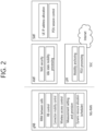
- FIG. 2 illustrates the functional split between NG-RAN and 5GC.
- the gNB may provide functions, such as Inter Cell Radio Resource Management (RRM), Radio Bearer (RB) control, Connection Mobility Control, Radio Admission Control, Measurement Configuration & Provision, Dynamic Resource Allocation, and so on.
- RRM Inter Cell Radio Resource Management
- RB Radio Bearer
- An AMF may provide functions, such as Non-Access Stratum (NAS) security, idle state mobility processing, and so on.
- a UPF may provide functions, such as Mobility Anchoring, Protocol Data Unit (PDU) processing, and so on.
- a Session Management Function (SMF) may provide functions, such as user equipment (UE) Internet Protocol (IP) address allocation, PDU session control, and so on.
- UE user equipment
- IP Internet Protocol
- FIG. 3 illustrates examples of 5G usage scenarios to which the technical features of the present disclosure can be applied.
- the 5G usage scenarios shown in FIG. 3 are only exemplary, and the technical features of the present disclosure can be applied to other 5G usage scenarios which are not shown in FIG. 3 .
- the three main requirements areas of 5G include (1) enhanced mobile broadband (eMBB) domain, (2) massive machine type communication (mMTC) area, and (3) ultra-reliable and low latency communications (URLLC) area.
- eMBB enhanced mobile broadband
- mMTC massive machine type communication
- URLLC ultra-reliable and low latency communications
- Some use cases may require multiple areas for optimization and, other use cases may only focus on only one key performance indicator (KPI).
- KPI key performance indicator
- eMBB focuses on across-the-board enhancements to the data rate, latency, user density, capacity and coverage of mobile broadband access.
- the eMBB aims ⁇ 10 Gbps of throughput.
- eMBB far surpasses basic mobile Internet access and covers rich interactive work and media and entertainment applications in cloud and/or augmented reality.
- Data is one of the key drivers of 5G and may not be able to see dedicated voice services for the first time in the 5G era.
- the voice is expected to be processed as an application simply using the data connection provided by the communication system.
- the main reason for the increased volume of traffic is an increase in the size of the content and an increase in the number of applications requiring high data rates.
- Streaming services (audio and video), interactive video and mobile Internet connectivity will become more common as more devices connect to the Internet. Many of these applications require always-on connectivity to push real-time information and notifications to the user.
- Cloud storage and applications are growing rapidly in mobile communication platforms, which can be applied to both work and entertainment.
- Cloud storage is a special use case that drives growth of uplink data rate.
- 5G is also used for remote tasks on the cloud and requires much lower end-to-end delay to maintain a good user experience when the tactile interface is used.
- cloud games and video streaming are another key factor that increases the demand for mobile broadband capabilities. Entertainment is essential in smartphones and tablets anywhere, including high mobility environments such as trains, cars and airplanes.
- Another use case is augmented reality and information retrieval for entertainment.
- augmented reality requires very low latency and instantaneous data amount.
- mMTC is designed to enable communication between devices that are low-cost, massive in number and battery-driven, intended to support applications such as smart metering, logistics, and field and body sensors.
- mMTC aims ⁇ 10 years on battery and/or ⁇ 1 million devices/km 2 .
- mMTC allows seamless integration of embedded sensors in all areas and is one of the most widely used 5G applications. Potentially by 2020, IoT devices are expected to reach 20.4 billion.
- Industrial IoT is one of the areas where 5G plays a key role in enabling smart cities, asset tracking, smart utilities, agriculture and security infrastructures.
- URLLC will make it possible for devices and machines to communicate with ultra-reliability, very low latency and high availability, making it ideal for vehicular communication, industrial control, factory automation, remote surgery, smart grids and public safety applications.
- URLLC aims ⁇ 1ms of latency.
- URLLC includes new services that will change the industry through links with ultra-reliability / low latency, such as remote control of key infrastructure and self-driving vehicles.
- the level of reliability and latency is essential for smart grid control, industrial automation, robotics, drone control and coordination.
- 5G can complement fiber-to-the-home (FTTH) and cable-based broadband (or DOCSIS) as a means of delivering streams rated from hundreds of megabits per second to gigabits per second.
- This high speed can be required to deliver TVs with resolutions of 4K or more (6K, 8K and above) as well as virtual reality (VR) and augmented reality (AR).
- VR and AR applications include mostly immersive sporting events. Certain applications may require special network settings. For example, in the case of a VR game, a game company may need to integrate a core server with an edge network server of a network operator to minimize delay.
- Automotive is expected to become an important new driver for 5G, with many use cases for mobile communications to vehicles. For example, entertainment for passengers demands high capacity and high mobile broadband at the same time. This is because future users will continue to expect high-quality connections regardless of their location and speed.
- Another use case in the automotive sector is an augmented reality dashboard.
- the driver can identify an object in the dark on top of what is being viewed through the front window through the augmented reality dashboard.
- the augmented reality dashboard displays information that will inform the driver about the object's distance and movement.
- the wireless module enables communication between vehicles, information exchange between the vehicle and the supporting infrastructure, and information exchange between the vehicle and other connected devices (e.g., devices accompanied by a pedestrian).
- the safety system allows the driver to guide the alternative course of action so that he can drive more safely, thereby reducing the risk of accidents.
- the next step will be a remotely controlled vehicle or self-driving vehicle. This requires a very reliable and very fast communication between different self-driving vehicles and between vehicles and infrastructure. In the future, a self-driving vehicle will perform all driving activities, and the driver will focus only on traffic that the vehicle itself cannot identify.
- the technical requirements of self-driving vehicles require ultra-low latency and high-speed reliability to increase traffic safety to a level not achievable by humans.
- Smart cities and smart homes which are referred to as smart societies, will be embedded in high density wireless sensor networks.
- the distributed network of intelligent sensors will identify conditions for cost and energy-efficient maintenance of a city or house. A similar setting can be performed for each home.
- Temperature sensors, windows and heating controllers, burglar alarms and appliances are all wirelessly connected. Many of these sensors typically require low data rate, low power and low cost. However, for example, real-time HD video may be required for certain types of devices for monitoring.
- the smart grid interconnects these sensors using digital information and communication technologies to collect and act on information. This information can include supplier and consumer behavior, allowing the smart grid to improve the distribution of fuel, such as electricity, in terms of efficiency, reliability, economy, production sustainability, and automated methods.
- the smart grid can be viewed as another sensor network with low latency.
- the health sector has many applications that can benefit from mobile communications.
- Communication systems can support telemedicine to provide clinical care in remote locations. This can help to reduce barriers to distance and improve access to health services that are not continuously available in distant rural areas. It is also used to save lives in critical care and emergency situations.
- Mobile communication based wireless sensor networks can provide remote monitoring and sensors for parameters such as heart rate and blood pressure.
- Wireless and mobile communications are becoming increasingly important in industrial applications. Wiring costs are high for installation and maintenance. Thus, the possibility of replacing a cable with a wireless link that can be reconfigured is an attractive opportunity in many industries. However, achieving this requires that wireless connections operate with similar delay, reliability, and capacity as cables and that their management is simplified. Low latency and very low error probabilities are new requirements that need to be connected to 5G.
- Logistics and freight tracking are important use cases of mobile communications that enable tracking of inventory and packages anywhere using location-based information systems. Use cases of logistics and freight tracking typically require low data rates, but require a large range and reliable location information.
- next-generation communication e.g., 6G
- 6G next-generation communication
- a 6G (wireless communication) system has purposes such as (i) very high data rate per device, (ii) a very large number of connected devices, (iii) global connectivity, (iv) very low latency, (v) decrease in energy consumption of battery-free IoT devices, (vi) ultra-reliable connectivity, and (vii) connected intelligence with machine learning capacity.
- the vision of the 6G system may include four aspects such as “intelligent connectivity”, “deep connectivity”, “holographic connectivity” and “ubiquitous connectivity", and the 6G system may satisfy the requirements shown in Table 1 below. That is, Table 1 shows the requirements of the 6G system. [Table 1] Per device peak data rate 1 Tbps E2E latency 1 ms Maximum spectral efficiency 100bps/Hz Mobility support Up to 1000km/hr Satellite integration Fully AI Fully Autonomous vehicle Fully XR Fully Haptic Communication Fully
- the 6G system may have key factors such as enhanced mobile broadband (eMBB), ultra-reliable low latency communications (URLLC), massive machine type communications (mMTC), AI integrated communication, tactile Internet, high throughput, high network capacity, high energy efficiency, low backhaul and access network congestion and enhanced data security.
- FIG. 4 is a diagram illustrating an example of a communication structure that can be provided in a 6G system.
- the 6G system will have 50 times higher simultaneous wireless communication connectivity than a 5G wireless communication system.
- URLLC which is the key feature of 5G, will become more important technology by providing end-to-end latency less than 1 ms in 6G communication.
- the 6G system may have much better volumetric spectrum efficiency unlike frequently used domain spectrum efficiency.
- the 6G system may provide advanced battery technology for energy harvesting and very long battery life and thus mobile devices may not need to be separately charged in the 6G system.
- new network characteristics may be as follows.
- AI was not involved in the 4G system.
- a 5G system will support partial or very limited AI.
- the 6G system will support AI for full automation.
- Advance in machine learning will create a more intelligent network for real-time communication in 6G.
- AI may determine a method of performing complicated target tasks using countless analysis. That is, AI may increase efficiency and reduce processing delay.
- AI may play an important role even in M2M, machine-to-human and human-to-machine communication.
- AI may be rapid communication in a brain computer interface (BCI).
- An AI based communication system may be supported by meta materials, intelligent structures, intelligent networks, intelligent devices, intelligent recognition radios, self-maintaining wireless networks and machine learning.
- AI-based physical layer transmission means applying a signal processing and communication mechanism based on an AI driver rather than a traditional communication framework in a fundamental signal processing and communication mechanism. For example, channel coding and decoding based on deep learning, signal estimation and detection based on deep learning, multiple input multiple output (MIMO) mechanisms based on deep learning, resource scheduling and allocation based on AI, etc. may be included.
- MIMO multiple input multiple output
- Machine learning may be used for channel estimation and channel tracking and may be used for power allocation, interference cancellation, etc. in the physical layer of DL. In addition, machine learning may be used for antenna selection, power control, symbol detection, etc. in the MIMO system.
- DNN deep neutral network
- Deep learning-based AI algorithms require a lot of training data in order to optimize training parameters.
- a lot of training data is used offline.
- Static training for training data in a specific channel environment may cause a contradiction between the diversity and dynamic characteristics of a radio channel.
- the signals of the physical layer of wireless communication are complex signals.
- studies on a neural network for detecting a complex domain signal are further required.
- Machine learning refers to a series of operations to train a machine in order to create a machine which can perform tasks which cannot be performed or are difficult to be performed by people.
- Machine learning requires data and learning models.
- data learning methods may be roughly divided into three methods, that is, supervised learning, unsupervised learning and reinforcement learning.
- Neural network learning is to minimize output error.
- Neural network learning refers to a process of repeatedly inputting training data to a neural network, calculating the error of the output and target of the neural network for the training data, backpropagating the error of the neural network from the output layer of the neural network to an input layer in order to reduce the error and updating the weight of each node of the neural network.
- Supervised learning may use training data labeled with a correct answer and the unsupervised learning may use training data which is not labeled with a correct answer. That is, for example, in case of supervised learning for data classification, training data may be labeled with a category.
- the labeled training data may be input to the neural network, and the output (category) of the neural network may be compared with the label of the training data, thereby calculating the error.
- the calculated error is backpropagated from the neural network backward (that is, from the output layer to the input layer), and the connection weight of each node of each layer of the neural network may be updated according to backpropagation. Change in updated connection weight of each node may be determined according to the learning rate.
- Calculation of the neural network for input data and backpropagation of the error may configure a learning cycle (epoch).
- the learning data is differently applicable according to the number of repetitions of the learning cycle of the neural network. For example, in the early phase of learning of the neural network, a high learning rate may be used to increase efficiency such that the neural network rapidly ensures a certain level of performance and, in the late phase of learning, a low learning rate may be used to increase accuracy.
- the learning method may vary according to the feature of data. For example, for the purpose of accurately predicting data transmitted from a transmitter in a receiver in a communication system, learning may be performed using supervised learning rather than unsupervised learning or reinforcement learning.
- the learning model corresponds to the human brain and may be regarded as the most basic linear model.
- a paradigm of machine learning using a neural network structure having high complexity, such as artificial neural networks, as a learning model is referred to as deep learning.
- Neural network cores used as a learning method may roughly include a deep neural network (DNN) method, a convolutional deep neural network (CNN) method and a recurrent Boltzmman machine (RNN) method. Such a learning model is applicable.
- DNN deep neural network
- CNN convolutional deep neural network
- RNN recurrent Boltzmman machine
- An artificial neural network is an example of connecting several perceptrons.
- FIG. 5 schematically illustrates an example of a perceptron structure.
- the huge artificial neural network structure may extend the simplified perceptron structure shown in FIG. 5 and apply input vectors to different multi-dimensional perceptrons.
- an input value or an output value is referred to as a node.
- the perceptron structure shown in FIG. 5 can be described as being composed of a total of three layers based on input values and output values.
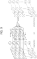
- An artificial neural network in which H number of (d + 1) dimensional perceptrons exist between the 1st layer and the 2nd layer and K number of (H + 1) dimensional perceptrons between the 2nd layer and the 3rd layer can be expressed as shown in FIG. 6 .
- FIG. 6 schematically illustrates an example of a multilayer perceptron structure.
- the layer where the input vector is located is called the input layer
- the layer where the final output value is located is called the output layer
- all the layers located between the input layer and the output layer are called hidden layers.
- three layers are disclosed, but when counting the number of layers of an actual artificial neural network, since the count excludes the input layer, it can be regarded as a total of two layers.
- the artificial neural network is composed of two-dimensionally connected perceptrons of basic blocks.
- the above-described input layer, hidden layer, and output layer can be jointly applied to various artificial neural network structures such as CNN and RNN, which will be described later, as well as multi-layer perceptrons.
- CNN neural network
- RNN multi-layer perceptrons
- DNN deep neural network
- FIG. 7 schematically illustrates a deep neural network example.
- the deep neural network shown in FIG. 7 is a multi-layer perceptron consisting of 8 hidden layers + 8 output layers.
- the multilayer perceptron structure is expressed as a fully-connected neural network.
- a fully-connected neural network there is no connection relationship between nodes located on the same layer, and there is a connection relationship only between nodes located on adjacent layers.
- DNN has a fully connected neural network structure and is composed of a combination of multiple hidden layers and activation functions, so it can be usefully applied to identify the correlation characteristics between inputs and outputs.
- the correlation characteristic may mean a joint probability of input and output.
- FIG. 8 schematically illustrates an example of a convolutional neural network.
- nodes located inside one layer are arranged in a one-dimensional vertical direction.
- the nodes are two-dimensionally arranged with w nodes horizontally and h nodes vertically (convolutional neural network structure of FIG. 8 ).
- a weight is added for each connection in the connection process from one input node to the hidden layer, a total of hXw weights must be considered.
- hXw nodes in the input layer a total of h2w2 weights are required between two adjacent layers.
- the convolutional neural network of FIG. 8 has a problem that the number of weights increases exponentially according to the number of connections, so instead of considering all mode connections between adjacent layers, assuming that a filter having a small size exists, as shown in FIG. 9 , a weighted sum and an activation function operation are performed on a portion where the filters overlap.
- FIG. 9 schematically illustrates an example of a filter operation in a convolutional neural network.
- One filter has weights corresponding to the number of filters, and learning of weights can be performed so that a specific feature on an image can be extracted as a factor and output.
- a 3X3 size filter is applied to the 3X3 area at the top left of the input layer, and the weighted sum and activation function calculations are performed on the corresponding node, and the resulting output value is stored in z22.
- the filter scans the input layer while moving horizontally and vertically at regular intervals, performs weighted sum and activation function calculations, and places the output value at the position of the current filter.
- This operation method is similar to the convolution operation for images in the field of computer vision, so the deep neural network of this structure is called a convolutional neural network (CNN), a hidden layer generated as a result of the convolution operation is called a convolutional layer.
- a neural network having a plurality of convolutional layers is referred to as a deep convolutional neural network (DCNN).
- the number of weights may be reduced by calculating a weighted sum by including only nodes located in a region covered by the filter in the node where the current filter is located. This allows one filter to be used to focus on features for a local area. Accordingly, CNN can be effectively applied to image data processing in which a physical distance in a 2D area is an important criterion. Meanwhile, in the CNN, a plurality of filters may be applied immediately before the convolution layer, and a plurality of output results may be generated through a convolution operation of each filter.
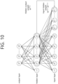
- a structure in which an output vector (hidden vector) of a hidden layer output at a specific point in time is input together with the next element in a sequence to an artificial neural network is called a recurrent neural network structure.
- FIG. 10 schematically illustrates an example of a neural network structure in which a cyclic loop exists.
- a recurrent neural network is a structure that applies a weighted sum and an activation function in the process of inputting an element (x1(t), x2(t)..., xd(t)) of any gaze t on the data sequence to the fully connected neural network, by entering together the hidden vector (z1(t-1), z2(t-1)..., zH(t-1)) of the immediately preceding time point t-1.
- the reason why the hidden vector is transmitted to the next time point in this way is that information in the input vector at previous time points is regarded as being accumulated in the hidden vector of the current time point.
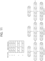
- FIG. 11 schematically illustrates an example of an operating structure of a recurrent neural network.
- the recurrent neural network operates in a sequence of predetermined views with respect to an input data sequence.
- a deep recurrent neural network a recurrent neural network
- Recurrent neural networks are designed to be usefully applied to sequence data (e.g., natural language processing).
- a neural network core used as a learning method, in addition to DNN, CNN, and RNN, various deep learning techniques such as Restricted Boltzmann Machine (RBM), deep belief networks (DBN), and deep Q-Network may be included. It can be applied to fields such as computer vision, voice recognition, natural language processing, and voice/signal processing.
- RBM Restricted Boltzmann Machine
- DNN deep belief networks
- Q-Network deep Q-Network
- AI-based physical layer transmission means applying a signal processing and communication mechanism based on an AI driver rather than a traditional communication framework in fundamental signal processing and communication mechanisms. For example, deep learning-based channel coding and decoding, deep learning-based signal estimation and detection, deep learning-based MIMO mechanism, AI-based resource scheduling and may include allocations, etc.
- a data rate may increase by increasing bandwidth. This may be performed by using sub-TH communication with wide bandwidth and applying advanced massive MIMO technology.
- THz waves which are known as sub-millimeter radiation, generally indicates a frequency band between 0.1 THz and 10 THz with a corresponding wavelength in a range of 0.03 mm to 3 mm.
- a band range of 100 GHz to 300 GHz (sub THz band) is regarded as a main part of the THz band for cellular communication.
- the 6G cellular communication capacity increases.
- 300 GHz to 3 THz of the defined THz band is in a far infrared (IR) frequency band.
- IR far infrared
- a band of 300 GHz to 3 THz is a part of an optical band but is at the border of the optical band and is just behind an RF band. Accordingly, the band of 300 GHz to 3 THz has similarity with RF.
- FIG. 12 illustrates an example of an electromagnetic spectrum.
- the main characteristics of THz communication include (i) bandwidth widely available to support a very high data rate and (ii) high path loss occurring at a high frequency (a high directional antenna is indispensable).
- a narrow beam width generated in the high directional antenna reduces interference.
- the small wavelength of a THz signal allows a larger number of antenna elements to be integrated with a device and BS operating in this band. Therefore, an advanced adaptive arrangement technology capable of overcoming a range limitation may be used.
- Optical wireless communication (OWC) technology is planned for 6G communication in addition to RF based communication for all possible device-to-access networks. This network is connected to a network-to-backhaul/fronthaul network connection.
- OWC technology has already been used since 4G communication systems but will be more widely used to satisfy the requirements of the 6G communication system.
- OWC technologies such as light fidelity/visible light communication, optical camera communication and free space optical (FSO) communication based on wide band are well-known technologies. Communication based on optical wireless technology may provide a very high data rate, low latency and safe communication.
- Light detection and ranging (LiDAR) may also be used for ultra high resolution 3D mapping in 6G communication based on wide band.
- FSO may be a good technology for providing backhaul connection in the 6G system along with the optical fiber network.
- FSO supports mass backhaul connections for remote and non-remote areas such as sea, space, underwater and isolated islands.
- FSO also supports cellular base station connections.
- MIMO technology One of core technologies for improving spectrum efficiency is MIMO technology.
- MIMO technology When MIMO technology is improved, spectrum efficiency is also improved. Accordingly, massive MIMO technology will be important in the 6G system. Since MIMO technology uses multiple paths, multiplexing technology and beam generation and management technology suitable for the THz band should be significantly considered such that data signals are transmitted through one or more paths.
- a blockchain will be important technology for managing large amounts of data in future communication systems.
- the blockchain is a form of distributed ledger technology, and distributed ledger is a database distributed across numerous nodes or computing devices. Each node duplicates and stores the same copy of the ledger.
- the blockchain is managed through a peer-to-peer (P2P) network. This may exist without being managed by a centralized institution or server.
- P2P peer-to-peer
- Blockchain data is collected together and organized into blocks. The blocks are connected to each other and protected using encryption.
- the blockchain completely complements large-scale IoT through improved interoperability, security, privacy, stability and scalability. Accordingly, the blockchain technology provides several functions such as interoperability between devices, high-capacity data traceability, autonomous interaction of different IoT systems, and large-scale connection stability of 6G communication systems.
- the 6G system integrates terrestrial and public networks to support vertical expansion of user communication.
- a 3D BS will be provided through low-orbit satellites and UAVs. Adding new dimensions in terms of altitude and related degrees of freedom makes 3D connections significantly different from existing 2D networks.
- unsupervised reinforcement learning of the network is promising.
- the supervised learning method cannot label the vast amount of data generated in 6G. Labeling is not required for unsupervised learning.
- this technique can be used to autonomously build a representation of a complex network. Combining reinforcement learning with unsupervised learning may enable the network to operate in a truly autonomous way.
- UAV unmanned aerial vehicle
- a base station entity is installed in the UAV to provide cellular connectivity.
- UAVs have certain features, which are not found in fixed base station infrastructures, such as easy deployment, strong line-of-sight links, and mobility-controlled degrees of freedom.
- the UAV can easily handle this situation.
- the UAV will be a new paradigm in the field of wireless communications. This technology facilitates the three basic requirements of wireless networks, such as eMBB, URLLC and mMTC.
- the UAV can also serve a number of purposes, such as network connectivity improvement, fire detection, disaster emergency services, security and surveillance, pollution monitoring, parking monitoring, and accident monitoring. Therefore, UAV technology is recognized as one of the most important technologies for 6G communication.
- the tight integration of multiple frequencies and heterogeneous communication technologies is very important in the 6G system. As a result, a user can seamlessly move from network to network without having to make any manual configuration in the device. The best network is automatically selected from the available communication technologies. This will break the limitations of the cell concept in wireless communication. Currently, user movement from one cell to another cell causes too many handovers in a high-density network, and causes handover failure, handover delay, data loss and ping-pong effects. 6G cell-free communication will overcome all of them and provide better QoS. Cell-free communication will be achieved through multi-connectivity and multi-tier hybrid technologies and different heterogeneous radios in the device.
- WIET uses the same field and wave as a wireless communication system.
- a sensor and a smartphone will be charged using wireless power transfer during communication.
- WIET is a promising technology for extending the life of battery charging wireless systems. Therefore, devices without batteries will be supported in 6G communication.
- An autonomous wireless network is a function for continuously detecting a dynamically changing environment state and exchanging information between different nodes.
- sensing will be tightly integrated with communication to support autonomous systems.
- each access network is connected by optical fiber and backhaul connection such as FSO network.
- FSO network optical fiber and backhaul connection
- Beamforming is a signal processing procedure that adjusts an antenna array to transmit radio signals in a specific direction. This is a subset of smart antennas or advanced antenna systems. Beamforming technology has several advantages, such as high signal-to-noise ratio, interference prevention and rejection, and high network efficiency.
- Hologram beamforming (HBF) is a new beamforming method that differs significantly from MIMO systems because this uses a software-defined antenna. HBF will be a very effective approach for efficient and flexible transmission and reception of signals in multi-antenna communication devices in 6G.
- Big data analysis is a complex process for analyzing various large data sets or big data. This process finds information such as hidden data, unknown correlations, and customer disposition to ensure complete data management. Big data is collected from various sources such as video, social networks, images and sensors. This technology is widely used for processing massive data in the 6G system.
- the LIS is an artificial surface made of electromagnetic materials, and can change propagation of incoming and outgoing radio waves.
- the LIS can be viewed as an extension of massive MIMO, but differs from the massive MIMO in array structures and operating mechanisms.
- the LIS has an advantage such as low power consumption, because this operates as a reconfigurable reflector with passive elements, that is, signals are only passively reflected without using active RF chains.
- each of the passive reflectors of the LIS must independently adjust the phase shift of an incident signal, this may be advantageous for wireless communication channels.
- the reflected signal can be collected at a target receiver to boost the received signal power.
- the THz wave is located between radio frequency (RF)/millimeter (mm) and infrared bands, and (i) transmits non-metallic/non-polarizable materials better than visible/infrared rays and has a shorter wavelength than the RF/millimeter wave and thus high straightness and is capable of beam convergence.
- the photon energy of the THz wave is only a few meV and thus is harmless to the human body.
- a frequency band which will be used for THz wireless communication may be a D-band (110 GHz to 170 GHz) or a H-band (220 GHz to 325 GHz) band with low propagation loss due to molecular absorption in air.
- Standardization discussion on THz wireless communication is being discussed mainly in IEEE 802.15 THz working group (WG), in addition to 3GPP, and standard documents issued by a task group (TG) of IEEE 802.15 (e.g., TG3d, TG3e) specify and supplement the description of this disclosure.
- the THz wireless communication may be applied to wireless cognition, sensing, imaging, wireless communication, and THz navigation.
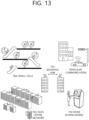
- FIG. 13 is a diagram illustrating an example of a THz communication application.
- a THz wireless communication scenario may be classified into a macro network, a micro network, and a nanoscale network.
- THz wireless communication may be applied to vehicle-to-vehicle (V2V) connection and backhaul/fronthaul connection.
- V2V vehicle-to-vehicle
- THz wireless communication may be applied to near-field communication such as indoor small cells, fixed point-to-point or multi-point connection such as wireless connection in a data center or kiosk downloading.
- Table 2 below is a table showing an example of a technology that can be used in a THz wave.
- Transceivers Device Available immature UTC-PD, RTD and SBD Modulation and coding Low order modulation techniques (OOK, QPSK), LDPC, Reed Soloman, Hamming, Polar, Turbo Antenna Omni and Directional, phased array with low number of antenna elements Bandwidth 69GHz (or 23 GHz) at 300GHz Channel models Partially Data rate 100Gbps Outdoor deployment No Free space loss High Coverage Low Radio Measurements 300GHz indoor Device size Few micrometers
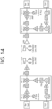
- FIG. 14 is a diagram illustrating an example of an electronic element-based THz wireless communication transceiver, the method of generating THz using an electronic device includes a method using a semiconductor device such as a resonance tunneling diode (RTD), a method using a local oscillator and a multiplier, a monolithic microwave integrated circuit (MMIC) method using a compound semiconductor high electron mobility transistor (HEMT) based integrated circuit, and a method using a Si-CMOS-based integrated circuit.
- a semiconductor device such as a resonance tunneling diode (RTD), a method using a local oscillator and a multiplier, a monolithic microwave integrated circuit (MMIC) method using a compound semiconductor high electron mobility transistor (HEMT) based integrated circuit, and a method using a Si-CMOS-based integrated circuit.
- RTD resonance tunneling diode
- MMIC monolithic microwave integrated circuit
- HEMT compound semiconductor high electron mobility transistor
- a multiplier (doubler, tripler, multiplier) is applied to increase the frequency, and radiation is performed by an antenna through a subharmonic mixer. Since the THz band forms a high frequency, a multiplier is essential.
- the multiplier is a circuit having an output frequency which is N times an input frequency, and matches a desired harmonic frequency, and filters out all other frequencies.
- beamforming may be implemented by applying an array antenna or the like to the antenna of FIG. 14 .
- IF represents an intermediate frequency
- a tripler and a multiplier represents a multiplier
- PA represents a power amplifier
- LNA represents a low noise amplifier
- PLL represents a phase-locked loop.
- FIG. 15 is a diagram illustrating an example of a method for generating a THz signal based on an optical device
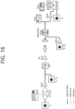
- FIG. 16 is a diagram illustrating an example of a THz wireless communication transceiver based on an optical device.
- the optical device-based THz wireless communication technology means a method of generating and modulating a THz signal using an optical device.
- the optical device-based THz signal generation technology refers to a technology that generates an ultrahigh-speed optical signal using a laser and an optical modulator, and converts it into a THz signal using an ultrahigh-speed photodetector. This technology is easy to increase the frequency compared to the technology using only the electronic device, can generate a high-power signal, and can obtain a flat response characteristic in a wide frequency band.
- a laser diode, a broadband optical modulator, and an ultrahigh-speed photodetector are required. In the case of FIG.
- an optical coupler refers to a semiconductor device that transmits an electrical signal using light waves to provide coupling with electrical isolation between circuits or systems
- a uni-travelling carrier photo-detector (UTC-PD) is one of photodetectors, which uses electrons as an active carrier and reduces the travel time of electrons by bandgap grading.
- the UTC-PD is capable of photodetection at 150 GHz or more.
- an erbium-doped fiber amplifier represents an optical fiber amplifier to which erbium is added
- a photo detector represents a semiconductor device capable of converting an optical signal into an electrical signal
- OSA represents an optical sub assembly in which various optical communication functions (e.g., photoelectric conversion, electrophotic conversion, etc.) are modularized as one component
- DSO represents a digital storage oscilloscope.
- FIG. 17 illustrates a structure of a transmitter based on a photonic source
- FIG. 18 illustrates a structure of an optical modulator.
- the optical source of the laser may change the phase of a signal by passing through the optical wave guide.
- data is carried by changing electrical characteristics through microwave contact or the like.
- the optical modulator output is formed in the form of a modulated waveform.
- a photoelectric modulator (O/E converter) may generate THz pulses according to optical rectification operation by a nonlinear crystal, photoelectric conversion (O/E conversion) by a photoconductive antenna, and emission from a bunch of relativistic electrons.
- the terahertz pulse (THz pulse) generated in the above manner may have a length of a unit from femto second to pico second.
- the photoelectric converter (O/E converter) performs down conversion using non-linearity of the device.
- available bandwidth may be classified based on oxygen attenuation 10 ⁇ 2 dB/km in the spectrum of up to 1 THz. Accordingly, a framework in which the available bandwidth is composed of several band chunks may be considered. As an example of the framework, if the length of the terahertz pulse (THz pulse) for one carrier (carrier) is set to 50 ps, the bandwidth (BW) is about 20 GHz.
- THz pulse terahertz pulse
- BW bandwidth
- Effective down conversion from the infrared band to the terahertz band depends on how to utilize the nonlinearity of the O/E converter. That is, for down-conversion into a desired terahertz band (THz band), design of the photoelectric converter (O/E converter) having the most ideal non-linearity to move to the corresponding terahertz band (THz band) is required. If a photoelectric converter (O/E converter) which is not suitable for a target frequency band is used, there is a high possibility that an error occurs with respect to the amplitude and phase of the corresponding pulse.
- a terahertz transmission/reception system may be implemented using one photoelectric converter.
- a multi-carrier system as many photoelectric converters as the number of carriers may be required, which may vary depending on the channel environment. Particularly, in the case of a multi-carrier system using multiple broadbands according to the plan related to the above-described spectrum usage, the phenomenon will be prominent.
- a frame structure for the multi-carrier system can be considered.
- the down-frequency-converted signal based on the photoelectric converter may be transmitted in a specific resource region (e.g., a specific frame).
- the frequency domain of the specific resource region may include a plurality of chunks. Each chunk may be composed of at least one component carrier (CC).
- CC component carrier
- Wireless communication systems are widely deployed to provide various types of communication services such as voice and data, and attempts to apply AI to communication systems are rapidly increasing.
- the AI integration methods that are being tried can be broadly categorized into communications for AI (C4AI), which develops communication technology to support AI, and AI for communications (AI4C), which utilizes AI to improve communication performance.
- C4AI communications for AI
- AI4C AI for communications
- federated learning a technique of distributed learning, is a way to update a common prediction model while protecting privacy by sharing only the weights or gradients of the model with the server without sharing the raw data of the device.
- methods such as split inference to distribute the load on devices, network edges, and cloud servers.
- Federated learning is one of the techniques of distributed machine learning, in which multiple devices that are the subject of learning share parameters such as weights and gradients of local models with the server, and the server aggregates the local model parameters of each device to update the global parameters.
- the raw data of each device is not shared, which reduces the communication overhead in the data transmission process and protects privacy.
- FIG. 19 schematically illustrates an orthogonal division access based federated learning operation process.
- Orthogonal multiple access based federated learning works as shown in FIG. 19 .
- Devices transmit local parameters over their respective allocated resources, and the server performs offline aggregation on the parameters received from the devices.
- the server derives a global parameter by averaging over all local parameters and transmits it back to the device.
- the time to update the global parameters is delayed as the number of devices participating in learning increases.
- FIG. 20 schematically illustrates airComp-based federated learning operation process.
- airComp is a method in which all devices utilize the same resources to transmit local parameters, as shown in FIG. 20 , and the signal received by the server can naturally obtain the sum of the local parameters due to the superposition property of the analog waveform.
- the transmitting end performs a pre-equalizer in the case of a single antenna, or a ZF beamforming technique in the case of multiple antennas to remove channel effects before transmission.
- channel inversion and ZF are characterized by a significant increase in Tx power in deep fading environments, which leads to performance degradation.
- the user transmits the signal by applying a pre-equalizer, and the server beamforms the received signal.
- the Rx beamforming cannot be designed in consideration of a specific user, but is determined in consideration of all users.
- the pre-equalizer cannot be performed as a simple channel inversion pre-equalization because it should remove the channels of two receiving antennas for one transmitting antenna in a situation where Rx beamforming is considered.
- the transmit signal should be transmitted in such a way that channel diversity is obtained by considering the multiple antennas of the server.
- FIG. 21 schematically illustrates an example of a deep fading channel.
- the user In order for the user to perform a channel inversion pre-equalizer, the user generates a transmit signal by multiplying the information by the Tx weight.
- the Tx weight is generated with the inversion value of the Uplink (UL) channel information
- the server performs Rx beamforming using multiple receiving antennas
- the Tx weight for the channel inversion pre-equalizer should remove the effects of both the UL channel and Rx beamforming, so the UL channel information and the Rx beamforming weight are used to generate the user's Tx weight.
- the Rx beamforming weight is determined using the UL channel information of all users and is common to all users, since all terminals should be considered instead of targeting a specific user.
- the method of generating Tx weight may be configured in many ways, and in the present disclosure, a method of effectively generating Tx beam weight when multiple antennas are present on the server in federated learning with airComp is provided.
- x ,x, X and means scalar, vector, matrix, and set.
- real(x) and imag(x) denote the real and imag parts of x.
- the present disclosure relates to a method and apparatus used in AI radio - C4AI.
- Te present disclosure describes a transmitter and receiver apparatus for improving reception reliability by mitigating the phenomenon of increased Peak-to-Average-Ratio (PAPR) or increased power of a transmit signal that may occur when pre-equalization is applied in a situation where the transmittable signal amplitude range of each transmitter is fixed.
- PAPR Peak-to-Average-Ratio
- CDMA may be implemented in radio technologies such as Universal Terrestrial Radio Access (UTRA) or CDMA2000.
- TDMA may be implemented in wireless technologies such as Global System for Mobile communications (GSM)/General Packet Radio Service (GPRS)/Enhanced Data Rates for GSM Evolution (EDGE).
- OFDMA may be implemented in wireless technologies such as IEEE 802.11 (Wi-Fi), IEEE 802.16 (WiMAX), IEEE 802-20, Evolved UTRA (E-UTRA), etc.
- UTRA is part of the Universal Mobile Telecommunications System (UMTS).
- 3rd Generation Partnership Project (3GPP) LTE Long Term Evolution
- E-UMTS Evolved UMTS
- LTE-Advanced (LTE-A)/LTE-A pro is an evolved version of 3GPP LTE.
- 3GPP New Radio or New Radio Access Technology (NR) is an evolution of 3GPP LTE/LTE-A/LTE-A pro.
- 3GPP 6G may be an evolution of 3GPP NR.
- LTE refers to 3GPP TS 36.xxx Release 8 and later technologies. More specifically, LTE technology after 3GPP TS 36.xxx Release 10 is referred to as LTE-A, and LTE technology after 3GPP TS 36.xxx Release 13 is referred to as LTE-A pro.
- 3GPP NR refers to technologies after TS 38.xxx Release 15.
- 3GPP 6G may refer to technology after TS Release 17 and/or Release 18.
- "xxx" means standard document detail number.
- LTE/NR/6G may be referred to collectively as the 3GPP system.
- terms, abbreviations, etc. used in the descriptions in the present disclosure reference may be made to standards documents published prior to the present disclosure.
- FIG. 22 is a flowchart of a method of receiving information, according to an embodiment of the present disclosure.
- the terminal may receive information about whether a pre-equalization factor is received directly from the base station (S2210). Since more specific details thereof are as described above and/or as will be described hereinafter, for the sake of simplicity of explanation, repetitive descriptions will be omitted.
- the terminal may transmit data over the airComp link based on the information (S2220). Since more specific details thereof are as described above and/or as will be described hereinafter, for the sake of simplicity of explanation, repetitive descriptions will be omitted.
- the terminal may receive the pre-equalization factor from the base station. Since more specific details thereof are as described above and/or as will be described hereinafter, for the sake of simplicity of explanation, repetitive descriptions will be omitted.
- the terminal may transmit the data over the airComp link based on the received pre-equalization factor. Since more specific details thereof are as described above and/or as will be described hereinafter, for the sake of simplicity of explanation, repetitive descriptions will be omitted.
- the terminal may receive from the base station a receive beamforming weight of the base station, and the terminal may receive from the base station channel information between the terminal and the base station. Since more specific details thereof are as described above and/or as will be described hereinafter, for the sake of simplicity of explanation, repetitive descriptions will be omitted.
- the terminal may receive the receive beamforming weight from the base station via broadcasting based on digital transmission link. Since more specific details thereof are as described above and/or as will be described hereinafter, for the sake of simplicity of explanation, repetitive descriptions will be omitted.
- the terminal may receive the channel information from the base station via dedicated signaling based on the digital transmission link. Since more specific details thereof are as described above and/or as will be described hereinafter, for the sake of simplicity of explanation, repetitive descriptions will be omitted.
- the terminal may derive the pre-equalization factor based on the receive beamforming weight and the channel information, and the terminal may transmit the data to the base station over the airComp link based on the derived pre-equalization factor. Since more specific details thereof are as described above and/or as will be described hereinafter, for the sake of simplicity of explanation, repetitive descriptions will be omitted.
- the terminal may receive the information over the digital communication link. Since more specific details thereof are as described above and/or as will be described hereinafter, for the sake of simplicity of explanation, repetitive descriptions will be omitted.
- the digital communication link may be a link based on Long Term Evolution (LTE) communication or New RAT (NR) communication
- the airComp link may be a link that supports a plurality of terminals, including the terminal, to transmit local parameters analogically or digitally utilizing the same resources. Since more specific details thereof are as described above and/or as will be described hereinafter, for the sake of simplicity of explanation, repetitive descriptions will be omitted.
- FIG. 23 schematically illustrates an example of pre-equalization.
- FIG. 21 is a conceptual diagram illustrating a process of a server receiving a signal from the u-th user when N is 2.
- the u-th user generates a signal s_(u,k) that is sent over the k-th resource from the n-th gradient ⁇ _(u,n).
- s_(u,k) is multiplied by a pre-equalization factor b_(u,k) to transmit a transmit signal x_(u,k) from the antenna.
- the signal After passing through the channels H_(u,0,k), H_(u,1,k), the signal reaches the server's antenna and is multiplied by the Rx beamforming weight a_(0,k), a_(1,k). Finally, the receive signal y_(0,k), y_(1,k) multiplied by the Rx beamforming weight is added to estimate the transmit signal s_(u,k) and detect the gradient from it.
- the pre-equalizer factor (Tx weight) at the transmitting end is as follows.
- b u , k 1 a 0 , k ⁇ H u , 0 , k + a 1 , k ⁇ H u , 1 , k
- a_(0,k) and a_(1,k) are common values applied to all users and are determined by the base station considering the UL channel information and Tx power limitation of the users transmitting signals over the k-th resource.
- the base station estimates the UL channel and informs the user. In this case, the base station calculates the Rx beamforming weight from the estimated UL channel information. Also, using the estimated UL channel information and the calculated Rx beamforming weight value, the base station determines a_(0,k), a_(1,k) and informs the terminals.
- y_(0,k), y_(1,k) are expressed by the following equation.
- y_k is expressed as the sum of the signals s_(u,k).
- N may be generalized and expressed as follows.
- the signal received by the server's n-th receiving antenna may be expressed as follows.
- the server needs to know the UL channel information of all users.
- the server needs to estimate the UL channel information of all users and transmit channel and Rx beamforming information and b_(u,k) information to each user, which requires a large overhead. Therefore, a more efficient way to update Rx beamforming weight and b_(u,k) is needed.
- method for delivering b_(u,k) to the user may be distinguished as follows.
- the base station delivers the calculated b_(u,k) to each user, and the base station calculates the Rx beamforming information using the UL channel estimation results of the users, and calculates b_(u,k) using the UL channel estimation results and the Rx beamforming information (direct delivery).
- the base station provides the UL channel estimation information and Rx beamforming information of the users to the terminal, and each user calculates its own b_(u,k), and the Rx beamforming information is common to the users within the base station (indirect delivery).
- the base station delivers control information to the user to choose between method 1 and method 2.
- the terminal may receive the above information (e.g., control information to choose between Method 1 and Method 2) about whether the pre-equalization factor is received directly from the base station.
- Terminals operated by each of method 1 and method 2 may coexist within a cell of a base station.
- FIG. 24 schematically illustrates a conceptual diagram of method 1 and method 2.
- the overhead per user in method 1 (b_(u,k) per user) is about 1/N compared to method 2 (channel information per user), except for the Rx beamforming information that is communicated in common. Therefore, if users move fast and b_(u,k) needs to be updated frequently, Method 1 may have less overhead than method 2, depending on the b_(u,k) update frequency. However, if users move slowly and b_(u,k) does not need to be updated frequently, method 2 may have less overhead by initially delivering channel information per user and then updating b_(u,k) by delivering common information, Rx beamforming information, to the user according to the situation in the base station (movement of other users).
- one of method 1 and method 2 is selected and operated.
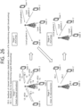
- FIG. 25 schematically illustrates of an example of method 2.
- FIG. 25 illustrates the application of Rx beamforming weight and b_(u,k) updating scheme proposed in method 2 when a new connection is present during an airComp federated learning already in progress.
- the procedure proceeds as follows.
- Stage 1 The server performs initial UL channel estimation for all users.
- the server forwards the estimated UL channel information and the calculated Rx beamforming weight information to the user (FB 1).
- the server estimates the UL channel of user 4 and estimates a new Rx beamforming weight using the already estimated UL channel of other users and the UL channel of user 4.
- the server(s) sends the estimated UL channel and Rx beamforming weight to user 4 (FB1) and only the Rx beamforming weight to other users (FB2).
- User 4 uses the obtained UL channel estimates and Rx beamforming weight to calculate b_(u,k).
- the other users update b_(u,k) using the already obtained UL channel estimates and the newly estimated Rx beamforming weight.
- the only user with a new UL channel estimate is the newly joined user 4, which greatly reduces the overhead compared to the method in Stage 1. Since the Rx beamforming weight information is common to all users, it may be broadcasted.
- AirComp federated learning is performed including user 4.
- FIG. 26 schematically illustrates another example of method 2.
- FIG. 26 illustrates the application of Rx beamforming weight and b_(u,k) updating scheme proposed in method 2 when a disconnection is present during an airComp federated learning already in progress.
- the procedure proceeds as follows.
- Stage 1 The server performs initial UL channel estimation for all users.
- the server forwards the estimated UL channel information and the calculated Rx beamforming weight information to the user (FB 1).
- the server calculates a new Rx beamforming weight by excluding UL channel of user 4 from other already estimated users.
- the server(s) communicate only the Rx beamforming weight to the users (FB2).
- the users update b_(u,k) using the already obtained UL channel estimates and the newly estimated Rx beamforming weight.
- the only user with a new UL channel estimate is the newly joined user 4, which greatly reduces the overhead compared to the method in Stage 1. Since the Rx beamforming weight information is common to all users, it may be broadcasted.
- AirComp federated learning is performed including user 4.
- a method may be provided in which the base station informs the user of selecting one of method 1 and method 2 in airComp federated learning in a single antenna user, multiple antenna server situation, and then the base station delivers and updates the Tx weight in the selected manner to the user.
- a method may be provided in which the base station delivers and updates the Tx weight by selecting between method 1 and method 2 depending on the movement speed of the user in the base station.
- a method and procedure for updating the Tx weight when there is a new connection and a disconnection during the airComp federated learning already being performed in a single antenna user, multiple antenna server situation may be provided.
- a method for calculating the Tx weight at the user side using UL channel information and Rx beamforming weight may be provided.
- a procedure for updating the Rx beamforming and Tx weight when a new user joins the airComp federated learning may be provided.
- a procedure for updating Rx beamforming and Tx weight may be provided when a user who was participating in the airComp federated learning is no longer participating in the learning.
- the terminal even if the terminal does not receive the above information, it is possible for the terminal to transmit data to the base station according to the example of method 1 described above, or to transmit data to the base station according to the example of method 2 described above.
- a particular terminal may support receiving the above information and may follow the example of method 1 or method 2 based on the above information. Or, another particular terminal may not support receiving the above information and may follow the example of method 1 or method 2 as predefined. Or, yet another particular terminal may support receiving the above information, but may follow the example of method 1 or method 2 under certain conditions or as predefined (either not receiving the above information, or ignoring the received information even if the above information is received).
- the terminal may perform pre-equalization and transmit the data to the base station according to the predefined method of either method 1 or method 2.
- the terminal may mean that the terminal does not receive or decode the above information on a certain channel (or a certain time, or a certain time interval) on which the above information is received.
- the predefined may mean that the base station instructs in advance in the initial access procedure to follow either method 1 or method 2 (or instructs after initial access, through dedicated signaling or broadcasting, to follow either method 1 or method 2).
- the predefined may mean that the specification defines that either method 1 or method 2 is to be followed.
- the predefined may mean that, as a device implementation issue, the device defines that either method 1 or method 2 is to be followed.
- the number of antennas of the user may also be considered. That is, the preceding description assumes that the user has one antenna, but the concepts and claims of the present disclosure are extensible to multiple antennas of the user.
- the embodiments of the present disclosure are applicable not only to a single antenna of a user, but also to multiple antennas of a user.
- the terminal performs communication via method 1 or receives communication via method 2.
- the problem that the base station performs many unnecessary operations and the problem that the base station transmits information to the terminal through dedicated signaling, which occupies a lot of radio resources can be solved.
- FIG. 27 is a flowchart of a method of receiving information, according to another embodiment of the present disclosure.
- the terminal may transmit a random access (RA) preamble to the base station (S2710). Since more specific details thereof are as described above and/or as will be described hereinafter, for the sake of simplicity of explanation, repetitive descriptions will be omitted.
- RA random access
- the terminal may receive a random access response (RAR) from the base station in response to the RA preamble (S2720). Since more specific details thereof are as described above and/or as will be described hereinafter, for the sake of simplicity of explanation, repetitive descriptions will be omitted.
- RAR random access response
- the terminal may perform a radio resource control (RRC) connection procedure with the base station (S2730). Since more specific details thereof are as described above and/or as will be described hereinafter, for the sake of simplicity of explanation, repetitive descriptions will be omitted.
- RRC radio resource control
- the terminal may establish a digital transmission link with the base station based on the RRC connection procedure (S2740). Since more specific details thereof are as described above and/or as will be described hereinafter, for the sake of simplicity of explanation, repetitive descriptions will be omitted.
- the terminal may establish an airComp link, which is a link for federated learning, with the base station (S2750). Since more specific details thereof are as described above and/or as will be described hereinafter, for the sake of simplicity of explanation, repetitive descriptions will be omitted.
- the terminal may receive information about whether a pre-equalization factor is received directly from the base station (S2760). Since more specific details thereof are as described above and/or as will be described hereinafter, for the sake of simplicity of explanation, repetitive descriptions will be omitted.
- the terminal may transmit data over said airComp link (S2770). Since more specific details thereof are as described above and/or as will be described hereinafter, for the sake of simplicity of explanation, repetitive descriptions will be omitted.
- FIG. 28 is a flowchart of a method of receiving information, from a terminal perspective, according to an embodiment of the present disclosure.
- the terminal may receive information about whether a pre-equalization factor is received directly from the base station (S2810). Since more specific details thereof are as described above and/or as will be described hereinafter, for the sake of simplicity of explanation, repetitive descriptions will be omitted.
- the terminal may transmit data over the airComp link (S2820). Since more specific details thereof are as described above and/or as will be described hereinafter, for the sake of simplicity of explanation, repetitive descriptions will be omitted.
- FIG. 29 is a block diagram of an example of a device for receiving information, from a terminal perspective, according to an embodiment of the present disclosure.
- a processor 2900 may include an information receiver 2910 and a data transmitter 2920.
- the processor 2900 may be the processor of FIGS. 29 through 41 .
- the information receiver 2910 may be configured to receive information about whether a pre-equalization factor is received directly from the base station. Since more specific details thereof are as described above and/or as will be described hereinafter, for the sake of simplicity of explanation, repetitive descriptions will be omitted.
- the data transmitter 2920 may be configured to transmit data over the airComp link based on the information. Since more specific details thereof are as described above and/or as will be described hereinafter, for the sake of simplicity of explanation, repetitive descriptions will be omitted.
- a terminal includes a transceiver, at least one memory, and at least one processor operably coupled to the at least one memory and the transceiver, and may be characterized in that the processor is configured to control the transceiver to transmit a random access (RA) preamble to a base station, configured to control the transceiver to receive a random access response (RAR) from the base station in response to the RA preamble, configured to perform a radio resource control (RRC) connection procedure with the base station, configured to establish a digital transmission link with the base station based on the RRC connection procedure, and configured to establish an airComp link, which is a link for federated learning, with the base station, the processor is configured to control the transceiver to receive information about whether a pre-equalization factor is received directly from the base station, and the processor is configured to control the transceiver to transmit data over the airComp link based on the information.
- RA random access
- RAR random access response
- RRC radio resource control
- a device includes at least one memory, and at least one processor operably coupled to the at least one memory, and may be characterized in that the processor is configured to control a transceiver to transmit a random access (RA) preamble to a base station, configured to control the transceiver to receive a random access response (RAR) from the base station in response to the RA preamble, configured to perform a radio resource control (RRC) connection procedure with the base station, configured to establish a digital transmission link with the base station based on the RRC connection procedure, and configured to establish an airComp link, which is a link for federated learning, with the base station, the processor is configured to control the transceiver to receive information about whether a pre-equalization factor is received directly from the base station, and the processor is configured to control the transceiver to transmit data over the airComp link based on the information.
- RA random access
- RAR random access response
- RRC radio resource control
- At least one computer readable medium comprising instructions, based on being executed by at least one processor, may be characterized in that the at least one processor is configured to control a transceiver to transmit a random access (RA) preamble to a base station, configured to control the transceiver to receive a random access response (RAR) from the base station in response to the RA preamble, configured to perform a radio resource control (RRC) connection procedure with the base station, configured to establish a digital transmission link with the base station based on the RRC connection procedure, and configured to establish an airComp link, which is a link for federated learning, with the base station, the at least one processor is configured to control the transceiver to receive information about whether a pre-equalization factor is received directly from the base station, and the at least one processor is configured to control the transceiver to transmit data over the airComp link based on the information.
- RA random access
- RAR random access response
- RRC radio resource control
- FIG. 30 is a flowchart of a method of transmitting information, from a base station perspective, according to an embodiment of the present disclosure.
- the base station may transmit information about whether a pre-equalization factor is received directly to the terminal (S3010). Since more specific details thereof are as described above and/or as will be described hereinafter, for the sake of simplicity of explanation, repetitive descriptions will be omitted.
- the base station may receive data over the airComp link (S3020). Since more specific details thereof are as described above and/or as will be described hereinafter, for the sake of simplicity of explanation, repetitive descriptions will be omitted.
- FIG. 31 is a block diagram of an example of a device for transmitting information, from a base station perspective, according to an embodiment of the present disclosure.
- a processor 3100 may include an information transmitter 3110 and a data receiver 3120.
- the processor 3100 may be the processor of FIGS. 29 through 41 .
- the information transmitter 3110 may be configured to transmit information about whether a pre-equalization factor is received directly to the terminal. Since more specific details thereof are as described above and/or as will be described hereinafter, for the sake of simplicity of explanation, repetitive descriptions will be omitted.
- the data receiver 3120 may be configured to receive data over the airComp link based on the information. Since more specific details thereof are as described above and/or as will be described hereinafter, for the sake of simplicity of explanation, repetitive descriptions will be omitted.
- FIG. 32 illustrates a communication system 1 applied to the present disclosure.
- a communication system 1 to which various embodiments of the present disclosure are applied includes wireless devices, Base Stations (BSs), and a network.
- the wireless devices represent devices performing communication using Radio Access Technology (RAT) (e.g., 5G New RAT (NR)) or Long-Term Evolution (LTE)) and may be referred to as communication/radio/5G devices.
- RAT Radio Access Technology
- the wireless devices may include, without being limited to, a robot 100a, vehicles 100b-1, 100b-2, an eXtended Reality (XR) device 100c, a hand-held device 100d, a home appliance 100e, an Internet of Things (IoT) device 100f, and an Artificial Intelligence (AI) device/server 400.
- RAT Radio Access Technology
- NR 5G New RAT
- LTE Long-Term Evolution
- the wireless devices may include, without being limited to, a robot 100a, vehicles 100b-1, 100b-2, an eXtended Reality (XR) device 100c, a hand-held device 100d
- the vehicles may include a vehicle having a wireless communication function, an autonomous vehicle, and a vehicle capable of performing communication between vehicles.
- the vehicles may include an Unmanned Aerial Vehicle (UAV) (e.g., a drone).
- UAV Unmanned Aerial Vehicle
- the XR device may include an Augmented Reality (AR)/Virtual Reality (VR)/Mixed Reality (MR) device and may be implemented in the form of a Head-Mounted Device (HMD), a Head-Up Display (HUD) mounted in a vehicle, a television, a smartphone, a computer, a wearable device, a home appliance device, a digital signage, a vehicle, a robot, and so on.
- the hand-held device may include a smartphone, a smartpad, a wearable device (e.g., a smartwatch or a smartglasses), and a computer (e.g., a notebook).
- the home appliance may include a TV, a refrigerator, and a washing machine.
- the IoT device may include a sensor and a smartmeter.
- the BSs and the network may be implemented as wireless devices and a specific wireless device 200a may operate as a BS/network node with respect to other wireless devices.
- the radio communication technologies implemented in the wireless devices in the present disclosure may include NarrowBand IoT (NB-IoT) technology for low-power communication as well as LTE, NR and 6G.
- NB-IoT technology may be an example of Low Power Wide Area Network (LPWAN) technology, may be implemented in specifications such as LTE Cat NB1 and/or LTE Cat NB2, and may not be limited to the above-mentioned names.
- LPWAN Low Power Wide Area Network
- the radio communication technologies implemented in the wireless devices in the present disclosure may communicate based on LTE-M technology.
- LTE-M technology may be an example of LPWAN technology and be called by various names such as enhanced MTC (eMTC).
- eMTC enhanced MTC
- LTE-M technology may be implemented in at least one of the various specifications, such as 1) LTE Cat 0, 2) LTE Cat M1, 3) LTE Cat M2, 4) LTE non-bandwidth limited (non-BL), 5) LTE-MTC, 6) LTE Machine Type Communication, and/or 7) LTE M, and may not be limited to the above-mentioned names.
- the radio communication technologies implemented in the wireless devices in the present disclosure may include at least one of ZigBee, Bluetooth, and/or LPWAN which take into account low-power communication, and may not be limited to the above-mentioned names.
- ZigBee technology may generate Personal Area Networks (PANs) associated with small/low-power digital communication based on various specifications such as IEEE 802.15.4 and may be called various names.
- PANs Personal Area Networks
- the wireless devices 100a ⁇ 100f may be connected to the network 300 via the BSs 200.
- An AI technology may be applied to the wireless devices 100a ⁇ 100f and the wireless devices 100a ⁇ 100f may be connected to the AI server 400 via the network 300.
- the network 300 may be configured using a 3G network, a 4G (e.g., LTE) network, or a 5G (e.g., NR) network.
- the wireless devices 100a ⁇ 100f may communicate with each other through the BSs 200/network 300, the wireless devices 100a ⁇ 100f may perform direct communication (e.g., sidelink communication) with each other without passing through the BSs/network.
- the vehicles 100b-1, 100b-2 may perform direct communication (e.g., Vehicle-to-Vehicle (V2V)/Vehicle-to-everything (V2X) communication).
- the IoT device e.g., a sensor
- the IoT device may perform direct communication with other IoT devices (e.g., sensors) or other wireless devices 100a ⁇ 100f.
- Wireless communication/connections 150a, 150b, 150c may be established between the wireless devices 100a ⁇ 100f/BS 200, or BS 200/BS 200.
- the wireless communication/connections may be established through various RATs (e.g., 5G NR) such as uplink/downlink communication 150a, sidelink communication 150b (or, D2D communication), or inter BS communication (e.g. relay, Integrated Access Backhaul (IAB)).
- the wireless devices and the BSs/the wireless devices may transmit/receive radio signals to/from each other through the wireless communication/connections 150a, 150b.
- the wireless communication/connections 150a, 150b may transmit/receive signals through various physical channels.
- various configuration information configuring processes various signal processing processes (e.g., channel encoding/decoding, modulation/demodulation, and resource mapping/demapping), and resource allocating processes, for transmitting/receiving radio signals, may be performed based on the various proposals of the present disclosure.
- various signal processing processes e.g., channel encoding/decoding, modulation/demodulation, and resource mapping/demapping
- resource allocating processes for transmitting/receiving radio signals
- NR supports a number of numerologies (or subcarrier spacing (SCS)) to support various 5G services.
- SCS subcarrier spacing
- SCS subcarrier spacing
- the NR frequency band may be defined as a frequency range of two types (FR1 and FR2).
- the number of frequency ranges may be changed, and for example, the frequency ranges of the two types (FR1 and FR2) may be shown in Table 3 below.
- FR1 may mean "sub 6 GHz range”
- FR2 may mean "above 6 GHz range” and may be called millimeter wave (mmW).
- mmW millimeter wave
- FR1 may include a band of 410 MHz to 7125 MHz as shown in Table 4 below. That is, FR1 may include a frequency band of 6 GHz (or 5850, 5900, 5925 MHz, etc.) or higher. For example, a frequency band of 6 GHz (or 5850, 5900, 5925 MHz, etc.) or higher included in FR1 may include an unlicensed band. The unlicensed band may be used for various purposes, and may be used, for example, for vehicle communication (e.g., autonomous driving). [Table 4] Frequency Range designation Corresponding frequency range Subcarrier Spacing FR1 410MHz - 7125MHz 15, 30, 60kHz FR2 24250MHz - 52600MHz 60, 120, 240kHz
- FIG. 33 illustrates an example of a wireless device that may be applicable to the present disclosure.
- a first wireless device 100 and a second wireless device 200 may transmit radio signals through a variety of RATs (e.g., LTE and NR).
- ⁇ the first wireless device 100 and the second wireless device 200 ⁇ may correspond to ⁇ the wireless device 100x, the BS 200 ⁇ and/or ⁇ the wireless device 100x, the wireless device 100x ⁇ of FIG. 32 .
- the first wireless device 100 may include one or more processors 102 and one or more memories 104 and additionally further include one or more transceivers 106 and/or one or more antennas 108.
- the processor(s) 102 may control the memory(s) 104 and/or the transceiver(s) 106 and may be configured to implement the descriptions, functions, procedures, proposals, methods, and/or operational flowcharts disclosed in this document.
- the processor(s) 102 may process information within the memory(s) 104 to generate first information/signals and then transmit radio signals including the first information/signals through the transceiver(s) 106.
- the processor(s) 102 may receive radio signals including second information/signals through the transceiver 106 and then store information obtained by processing the second information/signals in the memory(s) 104.
- the memory(s) 104 may be connected to the processor(s) 102 and may store a variety of information related to operations of the processor(s) 102.
- the memory(s) 104 may store software code including commands for performing a part or the entirety of processes controlled by the processor(s) 102 or for performing the descriptions, functions, procedures, proposals, methods, and/or operational flowcharts disclosed in this document.
- the processor(s) 102 and the memory(s) 104 may be a part of a communication modem/circuit/chip designed to implement RAT (e.g., LTE or NR).
- the transceiver(s) 106 may be connected to the processor(s) 102 and transmit and/or receive radio signals through one or more antennas 108.
- Each of the transceiver(s) 106 may include a transmitter and/or a receiver.
- the transceiver(s) 106 may be interchangeably used with Radio Frequency (RF) unit(s).
- the wireless device may represent a communication modem/circuit/chip.
- the second wireless device 200 may include one or more processors 202 and one or more memories 204 and additionally further include one or more transceivers 206 and/or one or more antennas 208.
- the processor(s) 202 may control the memory(s) 204 and/or the transceiver(s) 206 and may be configured to implement the descriptions, functions, procedures, proposals, methods, and/or operational flowcharts disclosed in this document.
- the processor(s) 202 may process information within the memory(s) 204 to generate third information/signals and then transmit radio signals including the third information/signals through the transceiver(s) 206.
- the processor(s) 202 may receive radio signals including fourth information/signals through the transceiver(s) 106 and then store information obtained by processing the fourth information/signals in the memory(s) 204.
- the memory(s) 204 may be connected to the processor(s) 202 and may store a variety of information related to operations of the processor(s) 202.
- the memory(s) 204 may store software code including commands for performing a part or the entirety of processes controlled by the processor(s) 202 or for performing the descriptions, functions, procedures, proposals, methods, and/or operational flowcharts disclosed in this document.
- the processor(s) 202 and the memory(s) 204 may be a part of a communication modem/circuit/chip designed to implement RAT (e.g., LTE or NR).
- the transceiver(s) 206 may be connected to the processor(s) 202 and transmit and/or receive radio signals through one or more antennas 208.
- Each of the transceiver(s) 206 may include a transmitter and/or a receiver.
- the transceiver(s) 206 may be interchangeably used with RF unit(s).
- the wireless device may represent a communication modem/circuit/chip.
- One or more protocol layers may be implemented by, without being limited to, one or more processors 102, 202.
- the one or more processors 102, 202 may implement one or more layers (e.g., functional layers such as PHY, MAC, RLC, PDCP, RRC, and SDAP).
- the one or more processors 102, 202 may generate one or more Protocol Data Units (PDUs) and/or one or more Service Data Unit (SDUs) according to the descriptions, functions, procedures, proposals, methods, and/or operational flowcharts disclosed in this document.
- PDUs Protocol Data Units
- SDUs Service Data Unit
- the one or more processors 102, 202 may generate messages, control information, data, or information according to the descriptions, functions, procedures, proposals, methods, and/or operational flowcharts disclosed in this document.
- the one or more processors 102, 202 may generate signals (e.g., baseband signals) including PDUs, SDUs, messages, control information, data, or information according to the descriptions, functions, procedures, proposals, methods, and/or operational flowcharts disclosed in this document and provide the generated signals to the one or more transceivers 106, 206.
- the one or more processors 102, 202 may receive the signals (e.g., baseband signals) from the one or more transceivers 106, 206 and obtain the PDUs, SDUs, messages, control information, data, or information according to the descriptions, functions, procedures, proposals, methods, and/or operational flowcharts disclosed in this document.
- signals e.g., baseband signals
- the one or more processors 102, 202 may be referred to as controllers, microcontrollers, microprocessors, or microcomputers.
- the one or more processors 102, 202 may be implemented by hardware, firmware, software, or a combination thereof.
- ASICs Application Specific Integrated Circuits
- DSPs Digital Signal Processors
- DSPDs Digital Signal Processing Devices
- PLDs Programmable Logic Devices
- FPGAs Field Programmable Gate Arrays
- the descriptions, functions, procedures, proposals, methods, and/or operational flowcharts disclosed in this document may be implemented using firmware or software and the firmware or software may be configured to include the modules, procedures, or functions.
- Firmware or software configured to perform the descriptions, functions, procedures, proposals, methods, and/or operational flowcharts disclosed in this document may be included in the one or more processors 102, 202 or stored in the one or more memories 104, 204 so as to be driven by the one or more processors 102, 202.
- the descriptions, functions, procedures, proposals, methods, and/or operational flowcharts disclosed in this document may be implemented using firmware or software in the form of code, commands, and/or a set of commands.
- the one or more memories 104, 204 may be connected to the one or more processors 102, 202 and store various types of data, signals, messages, information, programs, code, instructions, and/or commands.
- the one or more memories 104, 204 may be configured by Read-Only Memories (ROMs), Random Access Memories (RAMs), Electrically Erasable Programmable Read-Only Memories (EPROMs), flash memories, hard drives, registers, cash memories, computer-readable storage media, and/or combinations thereof.
- the one or more memories 104, 204 may be located at the interior and/or exterior of the one or more processors 102, 202.
- the one or more memories 104, 204 may be connected to the one or more processors 102, 202 through various technologies such as wired or wireless connection.
- the one or more transceivers 106, 206 may transmit user data, control information, and/or radio signals/channels, mentioned in the methods and/or operational flowcharts of this document, to one or more other devices.
- the one or more transceivers 106, 206 may receive user data, control information, and/or radio signals/channels, mentioned in the descriptions, functions, procedures, proposals, methods, and/or operational flowcharts disclosed in this document, from one or more other devices.
- the one or more transceivers 106, 206 may be connected to the one or more processors 102, 202 and transmit and receive radio signals.
- the one or more processors 102, 202 may perform control so that the one or more transceivers 106, 206 may transmit user data, control information, or radio signals to one or more other devices.
- the one or more processors 102, 202 may perform control so that the one or more transceivers 106, 206 may receive user data, control information, or radio signals from one or more other devices.
- the one or more transceivers 106, 206 may be connected to the one or more antennas 108, 208 and the one or more transceivers 106, 206 may be configured to transmit and receive user data, control information, and/or radio signals/channels, mentioned in the descriptions, functions, procedures, proposals, methods, and/or operational flowcharts disclosed in this document, through the one or more antennas 108, 208.
- the one or more antennas may be a plurality of physical antennas or a plurality of logical antennas (e.g., antenna ports).
- the one or more transceivers 106, 206 may convert received radio signals/channels, and so on, from RF band signals into baseband signals in order to process received user data, control information, radio signals/channels, and so on, using the one or more processors 102, 202.
- the one or more transceivers 106, 206 may convert the user data, control information, radio signals/channels, and so on, processed using the one or more processors 102, 202 from the base band signals into the RF band signals.
- the one or more transceivers 106, 206 may include (analog) oscillators and/or filters.
- FIG. 34 illustrates another example of a wireless device that may be applicable to the present disclosure.
- a wireless device may include at least one processor 102, 202, at least one memory 104, 204, at least one transceiver 106, 206, and one or more antennas 108, 208.
- FIG. 33 As a difference between the example of the wireless device described above in FIG. 33 and the example of the wireless device in FIG. 34 , in FIG. 33 , the processors 102 and 202 and the memories 104 and 204 are separated, but in the example of FIG. 34 , the memory 104, 204 is included in the processor 102, 202.
- processors 102 and 202 the memories 104 and 204, the transceivers 106 and 206, and one or more antennas 108 and 208 is as described above, in order to avoid unnecessary repetition of description, description of repeated description is omitted.
- FIG. 35 illustrates an example of a signal processing circuit for a transmission signal.
- a signal processing circuit 1000 may include scramblers 1010, modulators 1020, a layer mapper 1030, a precoder 1040, resource mappers 1050, and signal generators 1060.
- An operation/function of FIG. 35 may be performed, without being limited to, the processors 102, 202 and/or the transceivers 106, 206 of FIG. 33 .
- Hardware elements of FIG. 35 may be implemented by the processors 102, 202 and/or the transceivers 106, 206 of FIG. 33 .
- blocks 1010-1060 may be implemented by the processors 102, 202 of FIG. 33 .
- the blocks 1010-1050 may be implemented by the processors 102, 202 of FIG. 33 and the block 1060 may be implemented by the transceivers 106, 206 of FIG. 33 .
- Codewords may be converted into radio signals via the signal processing circuit 1000 of FIG. 35 .
- the codewords are encoded bit sequences of information blocks.
- the information blocks may include transport blocks (e.g., a UL-SCH transport block, a DL-SCH transport block).
- the radio signals may be transmitted through various physical channels (e.g., a PUSCH and a PDSCH).
- the codewords may be converted into scrambled bit sequences by the scramblers 1010.
- Scramble sequences used for scrambling may be generated based on an initialization value, and the initialization value may include ID information of a wireless device.
- the scrambled bit sequences may be modulated to modulation symbol sequences by the modulators 1020.
- a modulation scheme may include pi/2-Binary Phase Shift Keying (pi/2-BPSK), m-Phase Shift Keying (m-PSK), and m-Quadrature Amplitude Modulation (m-QAM).
- Complex modulation symbol sequences may be mapped to one or more transport layers by the layer mapper 1030.
- Modulation symbols of each transport layer may be mapped (precoded) to corresponding antenna port(s) by the precoder 1040.
- Outputs z of the precoder 1040 may be obtained by multiplying outputs y of the layer mapper 1030 by an N*M precoding matrix W.
- N is the number of antenna ports and M is the number of transport layers.
- the precoder 1040 may perform precoding after performing transform precoding (e.g., DFT) for complex modulation symbols. Alternatively, the precoder 1040 may perform precoding without performing transform precoding.
- transform precoding e.g., DFT
- the resource mappers 1050 may map modulation symbols of each antenna port to time-frequency resources.
- the time-frequency resources may include a plurality of symbols (e.g., a CP-OFDMA symbols and DFT-s-OFDMA symbols) in the time domain and a plurality of subcarriers in the frequency domain.
- the signal generators 1060 may generate radio signals from the mapped modulation symbols and the generated radio signals may be transmitted to other devices through each antenna.
- the signal generators 1060 may include Inverse Fast Fourier Transform (IFFT) modules, Cyclic Prefix (CP) inserters, Digital-to-Analog Converters (DACs), and frequency up-converters.
- IFFT Inverse Fast Fourier Transform
- CP Cyclic Prefix
- DACs Digital-to-Analog Converters
- Signal processing procedures for a signal received in the wireless device may be configured in a reverse manner of the signal processing procedures 1010-1060 of FIG. 35 .
- the wireless devices e.g., 100, 200 of FIG. 34
- the received radio signals may be converted into baseband signals through signal restorers.
- the signal restorers may include frequency downlink converters, Analog-to-Digital Converters (ADCs), CP remover, and Fast Fourier Transform (FFT) modules.
- ADCs Analog-to-Digital Converters
- FFT Fast Fourier Transform
- the baseband signals may be restored to codewords through a resource demapping procedure, a postcoding procedure, a demodulation processor, and a descrambling procedure.
- a signal processing circuit for a reception signal may include signal restorers, resource demappers, a postcoder, demodulators, descramblers, and decoders.
- FIG. 36 illustrates another example of a wireless device applied to the present disclosure.
- the wireless device may be implemented in various forms according to a use-case/service (refer to FIG. 32 ).
- wireless devices 100, 200 may correspond to the wireless devices 100, 200 of FIG. 33 and may be configured by various elements, components, units/portions, and/or modules.
- each of the wireless devices 100, 200 may include a communication unit 110, a control unit 120, a memory unit 130, and additional components 140.
- the communication unit may include a communication circuit 112 and transceiver(s) 114.
- the communication circuit 112 may include the one or more processors 102, 202 and/or the one or more memories 104, 204 of FIG. 33 .
- the transceiver(s) 114 may include the one or more transceivers 106, 206 and/or the one or more antennas 108, 208 of FIG. 33 .
- the control unit 120 is electrically connected to the communication unit 110, the memory 130, and the additional components 140 and controls overall operation of the wireless devices. For example, the control unit 120 may control an electric/mechanical operation of the wireless device based on programs/code/commands/information stored in the memory unit 130.
- the control unit 120 may transmit the information stored in the memory unit 130 to the exterior (e.g., other communication devices) via the communication unit 110 through a wireless/wired interface or store, in the memory unit 130, information received through the wireless/wired interface from the exterior (e.g., other communication devices) via the communication unit 110.
- the additional components 140 may be variously configured according to types of wireless devices.
- the additional components 140 may include at least one of a power unit/battery, input/output (I/O) unit, a driving unit, and a computing unit.
- the wireless device may be implemented in the form of, without being limited to, the robot (100a of FIG. 32 ), the vehicles (100b-1, 100b-2 of FIG. 32 ), the XR device (100c of FIG. 32 ), the hand-held device (100d of FIG. 32 ), the home appliance (100e of FIG. 32 ), the IoT device (100f of FIG.
- the wireless device may be used in a mobile or fixed place according to a use-example/service.
- the entirety of the various elements, components, units/portions, and/or modules in the wireless devices 100, 200 may be connected to each other through a wired interface or at least a part thereof may be wirelessly connected through the communication unit 110.
- the control unit 120 and the communication unit 110 may be connected by wire and the control unit 120 and first units (e.g., 130, 140) may be wirelessly connected through the communication unit 110.
- Each element, component, unit/portion, and/or module within the wireless devices 100, 200 may further include one or more elements.
- the control unit 120 may be configured by a set of one or more processors.
- control unit 120 may be configured by a set of a communication control processor, an application processor, an Electronic Control Unit (ECU), a graphical processing unit, and a memory control processor.
- memory 130 may be configured by a Random Access Memory (RAM), a Dynamic RAM (DRAM), a Read Only Memory (ROM)), a flash memory, a volatile memory, a non-volatile memory, and/or a combination thereof.
- RAM Random Access Memory
- DRAM Dynamic RAM
- ROM Read Only Memory
- flash memory a volatile memory
- non-volatile memory and/or a combination thereof.
- FIG. 36 An example of implementing FIG. 36 will be described in detail with reference to the drawings.
- FIG. 37 illustrates an example of a hand-held device applied to the present disclosure.
- the hand-held device may include smartphones, smartpads, wearable devices (e.g., smartwatches, smartglasses), and portable computers (e.g., laptops).
- a hand-held device may be referred to as a Mobile Station (MS), User Terminal (UT), Mobile Subscriber Station (MSS), Subscriber Station (SS), Advanced Mobile Station (AMS), or Wireless Terminal (WT).
- MS Mobile Station
- UT User Terminal
- MSS Mobile Subscriber Station
- SS Subscriber Station
- AMS Advanced Mobile Station
- WT Wireless Terminal
- a hand-held device 100 may include an antenna unit 108, a communication unit 110, a control unit 120, a memory unit 130, a power supply unit 140a, an interface unit 140b, and an I/O unit 140c.
- the antenna unit 108 may be configured as a part of the communication unit 110.
- Blocks 110-130/140a-140c correspond to the blocks 110-130/140 of FIG. 36 , respectively.
- the communication unit 110 may transmit and receive signals (e.g., data and control signals) to and from other wireless devices or BSs.
- the control unit 120 may perform various operations by controlling constituent elements of the hand-held device 100.
- the control unit 120 may include an Application Processor (AP).
- the memory unit 130 may store data/parameters/programs/code/commands needed to drive the hand-held device 100.
- the memory unit 130 may store input/output data/information.
- the power supply unit 140a may supply power to the hand-held device 100 and include a wired/wireless charging circuit, a battery, and so on.
- the interface unit 140b may support connection of the hand-held device 100 to other external devices.
- the interface unit 140b may include various ports (e.g., an audio I/O port and a video I/O port) for connection with external devices.
- the I/O unit 140c may input or output video information/signals, audio information/signals, data, and/or information input by a user.
- the I/O unit 140c may include a camera, a microphone, a user input unit, a display unit 140d, a speaker, and/or a haptic module.
- the I/O unit 140c may obtain information/signals (e.g., touch, text, voice, images, or video) input by a user and the obtained information/signals may be stored in the memory unit 130.
- the communication unit 110 may convert the information/signals stored in the memory into radio signals and transmit the converted radio signals to other wireless devices directly or to a BS.
- the communication unit 110 may receive radio signals from other wireless devices or the BS and then restore the received radio signals into original information/signals.
- the restored information/signals may be stored in the memory unit 130 and may be output as various types (e.g., text, voice, images, video, or haptic) through the I/O unit 140c.
- FIG. 38 illustrates an example of a vehicle or autonomous vehicle applied to the present disclosure.
- the vehicle or autonomous vehicle may be implemented by a mobile robot, a car, a train, a manned/unmanned Aerial Vehicle (AV), a ship, and so on.
- AV Aerial Vehicle
- a vehicle or autonomous vehicle 100 may include an antenna unit 108, a communication unit 110, a control unit 120, a driving unit 140a, a power supply unit 140b, a sensor unit 140c, and an autonomous driving unit 140d.
- the antenna unit 108 may be configured as a part of the communication unit 110.
- the blocks 110/130/140a-140d correspond to the blocks 110/130/140 of FIG. 36 , respectively.
- the communication unit 110 may transmit and receive signals (e.g., data and control signals) to and from external devices such as other vehicles, BSs (e.g., gNBs and road side units), and servers.
- the control unit 120 may perform various operations by controlling elements of the vehicle or the autonomous vehicle 100.
- the control unit 120 may include an Electronic Control Unit (ECU).
- the driving unit 140a may cause the vehicle or the autonomous vehicle 100 to drive on a road.
- the driving unit 140a may include an engine, a motor, a powertrain, a wheel, a brake, a steering device, and so on.
- the power supply unit 140b may supply power to the vehicle or the autonomous vehicle 100 and include a wired/wireless charging circuit, a battery, and so on.
- the sensor unit 140c may obtain a vehicle state, ambient environment information, user information, and so on.
- the sensor unit 140c may include an Inertial Measurement Unit (IMU) sensor, a collision sensor, a wheel sensor, a speed sensor, a slope sensor, a weight sensor, a heading sensor, a position module, a vehicle forward/backward sensor, a battery sensor, a fuel sensor, a tire sensor, a steering sensor, a temperature sensor, a humidity sensor, an ultrasonic sensor, an illumination sensor, a pedal position sensor, and so on.
- IMU Inertial Measurement Unit
- the autonomous driving unit 140d may implement technology for maintaining a lane on which a vehicle is driving, technology for automatically adjusting speed, such as adaptive cruise control, technology for autonomously driving along a determined path, technology for driving by automatically setting a path if a destination is set, and the like.
- the communication unit 110 may receive map data, traffic information data, and so on, from an external server.
- the autonomous driving unit 140d may generate an autonomous driving path and a driving plan from the obtained data.
- the control unit 120 may control the driving unit 140a such that the vehicle or the autonomous vehicle 100 may move along the autonomous driving path according to the driving plan (e.g., speed/direction control).
- the communication unit 110 may aperiodically/periodically obtain recent traffic information data from the external server and obtain surrounding traffic information data from neighboring vehicles.
- the sensor unit 140c may obtain a vehicle state and/or surrounding environment information.
- the autonomous driving unit 140d may update the autonomous driving path and the driving plan based on the newly obtained data/information.
- the communication unit 110 may transfer information on a vehicle position, the autonomous driving path, and/or the driving plan to the external server.
- the external server may predict traffic information data using AI technology, and so on, based on the information collected from vehicles or autonomous vehicles and provide the predicted traffic information data to the vehicles or the autonomous vehicles.
- FIG. 39 illustrates an example of a vehicle applied to the present disclosure.
- the vehicle may be implemented as a transport means, an aerial vehicle, a ship, and so on.
- a vehicle 100 may include a communication unit 110, a control unit 120, a memory unit 130, an I/O unit 140a, and a positioning unit 140b.
- the blocks 110-130/140a-140b correspond to blocks 110-130/140 of FIG. X3.
- the communication unit 110 may transmit and receive signals (e.g., data and control signals) to and from external devices such as other vehicles or BSs.
- the control unit 120 may perform various operations by controlling constituent elements of the vehicle 100.
- the memory unit 130 may store data/parameters/programs/code/commands for supporting various functions of the vehicle 100.
- the I/O unit 140a may output an AR/VR object based on information within the memory unit 130.
- the I/O unit 140a may include an HUD.
- the positioning unit 140b may obtain information on the position of the vehicle 100.
- the position information may include information on an absolute position of the vehicle 100, information on the position of the vehicle 100 within a traveling lane, acceleration information, and information on the position of the vehicle 100 from a neighboring vehicle.
- the positioning unit 140b may include a GPS and various sensors.
- the communication unit 110 of the vehicle 100 may receive map information and traffic information from an external server and store the received information in the memory unit 130.
- the positioning unit 140b may obtain the vehicle position information through the GPS and various sensors and store the obtained information in the memory unit 130.
- the control unit 120 may generate a virtual object based on the map information, traffic information, and vehicle position information and the I/O unit 140a may display the generated virtual object in a window in the vehicle 1410, 1420.
- the control unit 120 may determine whether the vehicle 100 normally drives within a traveling lane, based on the vehicle position information. If the vehicle 100 abnormally exits from the traveling lane, the control unit 120 may display a warning on the window in the vehicle through the I/O unit 140a. In addition, the control unit 120 may broadcast a warning message regarding driving abnormity to neighboring vehicles through the communication unit 110. According to situation, the control unit 120 may transmit the vehicle position information and the information on driving/vehicle abnormality to related organizations.
- FIG. 40 illustrates an example of an XR device applied to the present disclosure.
- the XR device may be implemented by an HMD, an HUD mounted in a vehicle, a television, a smartphone, a computer, a wearable device, a home appliance, a digital signage, a vehicle, a robot, and so on.
- an XR device 100a may include a communication unit 110, a control unit 120, a memory unit 130, an I/O unit 140a, a sensor unit 140b, and a power supply unit 140c.
- the blocks 110-130/140a-140c correspond to the blocks 110-130/140 of FIG. X3, respectively.
- the communication unit 110 may transmit and receive signals (e.g., media data and control signals) to and from external devices such as other wireless devices, hand-held devices, or media servers.
- the media data may include video, images, and sound.
- the control unit 120 may perform various operations by controlling constituent elements of the XR device 100a.
- the control unit 120 may be configured to control and/or perform procedures such as video/image acquisition, (video/image) encoding, and metadata generation and processing.
- the memory unit 130 may store data/parameters/programs/code/commands needed to drive the XR device 100a/generate XR object.
- the I/O unit 140a may obtain control information and data from the exterior and output the generated XR object.
- the I/O unit 140a may include a camera, a microphone, a user input unit, a display unit, a speaker, and/or a haptic module.
- the sensor unit 140b may obtain an XR device state, surrounding environment information, user information, and so on.
- the sensor unit 140b may include a proximity sensor, an illumination sensor, an acceleration sensor, a magnetic sensor, a gyro sensor, an inertial sensor, an RGB sensor, an IR sensor, a fingerprint recognition sensor, an ultrasonic sensor, a light sensor, a microphone and/or a radar.
- the power supply unit 140c may supply power to the XR device 100a and include a wired/wireless charging circuit, a battery, and so on.
- the memory unit 130 of the XR device 100a may include information (e.g., data) needed to generate the XR object (e.g., an AR/VR/MR object).
- the I/O unit 140a may receive a command for manipulating the XR device 100a from a user and the control unit 120 may drive the XR device 100a according to a driving command of a user. For example, when a user desires to watch a film or news through the XR device 100a, the control unit 120 transmits content request information to another device (e.g., a hand-held device 100b) or a media server through the communication unit 130.
- another device e.g., a hand-held device 100b
- a media server e.g., a media server
- the communication unit 130 may download/stream content such as films or news from another device (e.g., the hand-held device 100b) or the media server to the memory unit 130.
- the control unit 120 may control and/or perform procedures such as video/image acquisition, (video/image) encoding, and metadata generation/processing with respect to the content and generate/output the XR object based on information on a surrounding space or a real object obtained through the I/O unit 140a/sensor unit 140b.
- the XR device 100a may be wirelessly connected to the hand-held device 100b through the communication unit 110 and the operation of the XR device 100a may be controlled by the hand-held device 100b.
- the hand-held device 100b may operate as a controller of the XR device 100a.
- the XR device 100a may obtain information on a 3D position of the hand-held device 100b and generate and output an XR object corresponding to the hand-held device 100b.
- FIG. 41 illustrates an example of a robot applied to the present disclosure.
- the robot may be categorized into an industrial robot, a medical robot, a household robot, a military robot, and so on, according to a used purpose or field.
- a robot 100 may include a communication unit 110, a control unit 120, a memory unit 130, an I/O unit 140a, a sensor unit 140b, and a driving unit 140c.
- the blocks 110-130/140a-140c correspond to the blocks 110-130/140 of FIG. X3, respectively.
- the communication unit 110 may transmit and receive signals (e.g., driving information and control signals) to and from external devices such as other wireless devices, other robots, or control servers.
- the control unit 120 may perform various operations by controlling constituent elements of the robot 100.
- the memory unit 130 may store data/parameters/programs/code/commands for supporting various functions of the robot 100.
- the I/O unit 140a may obtain information from the exterior of the robot 100 and output information to the exterior of the robot 100.
- the I/O unit 140a may include a camera, a microphone, a user input unit, a display unit, a speaker, and/or a haptic module.
- the sensor unit 140b may obtain internal information of the robot 100, surrounding environment information, user information, and so on.
- the sensor unit 140b may include a proximity sensor, an illumination sensor, an acceleration sensor, a magnetic sensor, a gyro sensor, an inertial sensor, an IR sensor, a fingerprint recognition sensor, an ultrasonic sensor, a light sensor, a microphone, a radar, and so on.
- the driving unit 140c may perform various physical operations such as movement of robot joints. In addition, the driving unit 140c may cause the robot 100 to travel on the road or to fly.
- the driving unit 140c may include an actuator, a motor, a wheel, a brake, a propeller, and so on.
- FIG. 42 illustrates an example of an AI device applied to the present disclosure.
- the AI device may be implemented by a fixed device or a mobile device, such as a TV, a projector, a smartphone, a PC, a notebook, a digital broadcast terminal, a tablet PC, a wearable device, a Set Top Box (STB), a radio, a washing machine, a refrigerator, a digital signage, a robot, a vehicle, and so on.
- a fixed device such as a TV, a projector, a smartphone, a PC, a notebook, a digital broadcast terminal, a tablet PC, a wearable device, a Set Top Box (STB), a radio, a washing machine, a refrigerator, a digital signage, a robot, a vehicle, and so on.
- STB Set Top Box
- an AI device 100 may include a communication unit 110, a control unit 120, a memory unit 130, an I/O unit 140a/140b, a learning processor unit 140c, and a sensor unit 140d.
- the blocks 110-130/140a-140d correspond to blocks 110 ⁇ 130/140 of FIG. X3, respectively.
- the communication unit 110 may transmit and receive wired/radio signals (e.g., sensor information, user input, learning models, or control signals) to and from external devices such as other AI devices (e.g., 100x, 200, 400 of FIG. W1) or an AI server 200 using wired/wireless communication technology. To this end, the communication unit 110 may transmit information within the memory unit 130 to an external device and transmit a signal received from the external device to the memory unit 130.
- wired/radio signals e.g., sensor information, user input, learning models, or control signals
- external devices e.g., 100x, 200, 400 of FIG. W1
- an AI server 200 e.g., 100x, 200, 400 of FIG. W1
- the communication unit 110 may transmit information within the memory unit 130 to an external device and transmit a signal received from the external device to the memory unit 130.
- the control unit 120 may determine at least one feasible operation of the AI device 100, based on information which is determined or generated using a data analysis algorithm or a machine learning algorithm.
- the control unit 120 may perform an operation determined by controlling constituent elements of the AI device 100.
- the control unit 120 may request, search, receive, or use data of the learning processor unit 140c or the memory unit 130 and control the constituent elements of the AI device 100 to perform a predicted operation or an operation determined to be preferred among at least one feasible operation.
- the control unit 120 may collect history information including the operation contents of the AI device 100 and operation feedback by a user and store the collected information in the memory unit 130 or the learning processor unit 140c or transmit the collected information to an external device such as an AI server (400 of FIG. W1). The collected history information may be used to update a learning model.
- the memory unit 130 may store data for supporting various functions of the AI device 100.
- the memory unit 130 may store data obtained from the input unit 140a, data obtained from the communication unit 110, output data of the learning processor unit 140c, and data obtained from the sensor unit 140.
- the memory unit 130 may store control information and/or software code needed to operate/drive the control unit 120.
- the input unit 140a may obtain various types of data from the exterior of the AI device 100.
- the input unit 140a may obtain learning data for model learning, and input data to which the learning model is to be applied.
- the input unit 140a may include a camera, a microphone, and/or a user input unit.
- the output unit 140b may generate output related to a visual, auditory, or tactile sense.
- the output unit 140b may include a display unit, a speaker, and/or a haptic module.
- the sensing unit 140 may obtain at least one of internal information of the AI device 100, surrounding environment information of the AI device 100, and user information, using various sensors.
- the sensor unit 140 may include a proximity sensor, an illumination sensor, an acceleration sensor, a magnetic sensor, a gyro sensor, an inertial sensor, an RGB sensor, an IR sensor, a fingerprint recognition sensor, an ultrasonic sensor, a light sensor, a microphone, and/or a radar.
- the learning processor unit 140c may learn a model consisting of artificial neural networks, using learning data.
- the learning processor unit 140c may perform AI processing together with the learning processor unit of the AI server (400 of FIG. W1).
- the learning processor unit 140c may process information received from an external device through the communication unit 110 and/or information stored in the memory unit 130.
- an output value of the learning processor unit 140c may be transmitted to the external device through the communication unit 110 and may be stored in the memory unit 130.
Landscapes
- Engineering & Computer Science (AREA)
- Physics & Mathematics (AREA)
- Theoretical Computer Science (AREA)
- Computer Networks & Wireless Communication (AREA)
- Signal Processing (AREA)
- Data Mining & Analysis (AREA)
- Computing Systems (AREA)
- Biomedical Technology (AREA)
- Biophysics (AREA)
- Computational Linguistics (AREA)
- Life Sciences & Earth Sciences (AREA)
- Evolutionary Computation (AREA)
- General Health & Medical Sciences (AREA)
- Molecular Biology (AREA)
- Artificial Intelligence (AREA)
- General Engineering & Computer Science (AREA)
- General Physics & Mathematics (AREA)
- Mathematical Physics (AREA)
- Software Systems (AREA)
- Health & Medical Sciences (AREA)
- Power Engineering (AREA)
- Mobile Radio Communication Systems (AREA)
Applications Claiming Priority (1)
| Application Number | Priority Date | Filing Date | Title |
|---|---|---|---|
| PCT/KR2021/000337 WO2022149641A1 (fr) | 2021-01-11 | 2021-01-11 | Procédé et appareil d'apprentissage fédéré basés sur une configuration de serveur multi-antenne et d'utilisateur à antenne unique |
Publications (2)
| Publication Number | Publication Date |
|---|---|
| EP4276705A1 true EP4276705A1 (fr) | 2023-11-15 |
| EP4276705A4 EP4276705A4 (fr) | 2024-10-30 |
Family
ID=82357476
Family Applications (1)
| Application Number | Title | Priority Date | Filing Date |
|---|---|---|---|
| EP21917804.3A Pending EP4276705A4 (fr) | 2021-01-11 | 2021-01-11 | Procédé et appareil d'apprentissage fédéré basés sur une configuration de serveur multi-antenne et d'utilisateur à antenne unique |
Country Status (3)
| Country | Link |
|---|---|
| EP (1) | EP4276705A4 (fr) |
| KR (1) | KR20230131840A (fr) |
| WO (1) | WO2022149641A1 (fr) |
Cited By (1)
| Publication number | Priority date | Publication date | Assignee | Title |
|---|---|---|---|---|
| US20240250853A1 (en) * | 2021-05-21 | 2024-07-25 | Lenovo (Singapore) Pte. Ltd. | Determining a magnitude of a composite zero-forcing equalizer |
Families Citing this family (2)
| Publication number | Priority date | Publication date | Assignee | Title |
|---|---|---|---|---|
| CN117151249B (zh) * | 2023-08-08 | 2025-10-24 | 上海科技大学 | 一种基于空中计算和能量收集的联邦学习模型聚合方法 |
| KR102836697B1 (ko) | 2024-02-20 | 2025-07-21 | 국립부경대학교 산학협력단 | 다중 안테나를 활용한 차등 정보보호 제공 시스템 및 방법 |
Family Cites Families (4)
| Publication number | Priority date | Publication date | Assignee | Title |
|---|---|---|---|---|
| US8098776B2 (en) * | 2004-10-06 | 2012-01-17 | Broadcom Corporation | Method and system for pre-equalization in a single weight spatial multiplexing MIMO system |
| US7242961B2 (en) * | 2005-07-13 | 2007-07-10 | Broadcom Corporation | Channel reciprocity matrix determination in a wireless MIMO communication system |
| US10419086B2 (en) * | 2016-04-26 | 2019-09-17 | Samsung Electronics Co., Ltd. | Method and apparatus for enabling uplink MIMO |
| KR102406365B1 (ko) * | 2017-07-28 | 2022-06-08 | 삼성전자주식회사 | 단말 및 기지국 간의 rach 절차 수행 방법 및 이를 위한 기지국 및 단말 |
-
2021
- 2021-01-11 WO PCT/KR2021/000337 patent/WO2022149641A1/fr not_active Ceased
- 2021-01-11 EP EP21917804.3A patent/EP4276705A4/fr active Pending
- 2021-01-11 KR KR1020237023048A patent/KR20230131840A/ko active Pending
Cited By (2)
| Publication number | Priority date | Publication date | Assignee | Title |
|---|---|---|---|---|
| US20240250853A1 (en) * | 2021-05-21 | 2024-07-25 | Lenovo (Singapore) Pte. Ltd. | Determining a magnitude of a composite zero-forcing equalizer |
| US12483443B2 (en) * | 2021-05-21 | 2025-11-25 | Lenovo (Singapore) Pte. Ltd. | Determining a magnitude of a composite zero-forcing equalizer |
Also Published As
| Publication number | Publication date |
|---|---|
| WO2022149641A1 (fr) | 2022-07-14 |
| KR20230131840A (ko) | 2023-09-14 |
| EP4276705A4 (fr) | 2024-10-30 |
Similar Documents
| Publication | Publication Date | Title |
|---|---|---|
| US12506552B2 (en) | Method and apparatus for estimating channel in wireless communication system | |
| EP4187986A1 (fr) | Procédé et appareil de transmission et de réception de signal pour un terminal et une station de base dans un système de communication sans fil | |
| US12568000B2 (en) | Method and device for performing federated learning in wireless communication system | |
| KR20240133688A (ko) | 양자 통신 시스템에서 임의의 n-큐비트 얽힘 상태에 대하여 얽힘 오류를 검출하고 정정하기 위한 장치 및 방법 | |
| US20250038846A1 (en) | Device and method for performing quantum secure direct communication with reduced complexity in quantum communication system | |
| KR20230131820A (ko) | 차등 프라이버시를 고려한 신호 송수신 방법 및 상기 방법을 이용하는 장치 | |
| US20230308150A1 (en) | Method for generating beam of antenna in wireless communication system supporting thz band, and apparatus therefor | |
| US20230291476A1 (en) | Phase control device for continuous beam scanning in effective scan range and method therefor | |
| US12549967B2 (en) | Data partition-based modulation method and apparatus for federated learning | |
| US12362834B2 (en) | Frequency comb power control apparatus for 4D beamforming, and method therefor | |
| US12284273B2 (en) | Method and apparatus for correcting polarization distortion of faraday rotating mirror in plug-and-play quantum key distribution system | |
| KR20230131840A (ko) | 다중 안테나 서버 및 단일 안테나 유저 설정 기반 연합러닝 방법 및 장치 | |
| US20240414746A1 (en) | Device and method for performing, on basis of channel information, device grouping for federated learning-based aircomp of non-iid data environment in communication system | |
| US12176985B2 (en) | Method and device for adapting learning class-based system to AI MIMO | |
| US12294414B2 (en) | Method and device for multi-wavelength plug-and-play quantum key distribution without time delay due to wavelength conversion | |
| KR102938179B1 (ko) | 무선 통신 시스템에서 단말 및 기지국의 신호 송수신 방법 및 장치 | |
| KR102764497B1 (ko) | 다중 경로 및 파장 분할에 기반한 플러그 앤드 플레이 퀀텀 키 분배 방법 및 상기 방법을 이용하는 장치 | |
| KR20230146001A (ko) | 뉴럴 네트워크 기반 하향링크 제어 채널 송수신 방법 | |
| EP4239962A1 (fr) | Procédé et appareil permettant d'atténuer une limitation de puissance de transmission par transmission en chevauchement | |
| KR20250164247A (ko) | 양자 통신 시스템에서 비국소 잡음 특성을 갖는 간섭 채널에 대한 채널 코딩을 수행하기 위한 장치 및 방법 | |
| KR102938180B1 (ko) | 무선 통신 시스템에서 단말 및 기지국의 신호 송수신 방법 및 장치 | |
| US12513754B2 (en) | Hybrid transmission method and device using side information of local gradients | |
| KR20230131821A (ko) | 모델 스플릿 기반 추론 방법 및 상기 방법을 이용하는 장치 | |
| KR20260040158A (ko) | 양자 통신 시스템에서 얽힘 라우팅의 경로를 결정하기 위한 장치 및 방법 | |
| KR20260039716A (ko) | 무선 통신 시스템에서 멀티 모달 ai/ml 모델의 온라인 학습을 수행하기 위한 하기 위한 장치 및 방법 |
Legal Events
| Date | Code | Title | Description |
|---|---|---|---|
| STAA | Information on the status of an ep patent application or granted ep patent |
Free format text: STATUS: THE INTERNATIONAL PUBLICATION HAS BEEN MADE |
|
| PUAI | Public reference made under article 153(3) epc to a published international application that has entered the european phase |
Free format text: ORIGINAL CODE: 0009012 |
|
| STAA | Information on the status of an ep patent application or granted ep patent |
Free format text: STATUS: REQUEST FOR EXAMINATION WAS MADE |
|
| 17P | Request for examination filed |
Effective date: 20230718 |
|
| AK | Designated contracting states |
Kind code of ref document: A1 Designated state(s): AL AT BE BG CH CY CZ DE DK EE ES FI FR GB GR HR HU IE IS IT LI LT LU LV MC MK MT NL NO PL PT RO RS SE SI SK SM TR |
|
| DAV | Request for validation of the european patent (deleted) | ||
| DAX | Request for extension of the european patent (deleted) | ||
| REG | Reference to a national code |
Ref country code: DE Ref legal event code: R079 Free format text: PREVIOUS MAIN CLASS: G06N0020000000 Ipc: H04B0007045600 |
|
| A4 | Supplementary search report drawn up and despatched |
Effective date: 20240927 |
|
| RIC1 | Information provided on ipc code assigned before grant |
Ipc: H04L 27/26 20060101ALN20240923BHEP Ipc: H04L 25/03 20060101ALI20240923BHEP Ipc: G06N 3/098 20230101ALI20240923BHEP Ipc: G06N 3/0464 20230101ALI20240923BHEP Ipc: G06N 3/044 20230101ALI20240923BHEP Ipc: H04W 74/08 20090101ALI20240923BHEP Ipc: G06N 3/08 20230101ALI20240923BHEP Ipc: G06N 20/00 20190101ALI20240923BHEP Ipc: H04B 7/0456 20170101AFI20240923BHEP |