EP4276874B1 - Appareil de commutation moyenne tension - Google Patents
Appareil de commutation moyenne tension Download PDFInfo
- Publication number
- EP4276874B1 EP4276874B1 EP22173028.6A EP22173028A EP4276874B1 EP 4276874 B1 EP4276874 B1 EP 4276874B1 EP 22173028 A EP22173028 A EP 22173028A EP 4276874 B1 EP4276874 B1 EP 4276874B1
- Authority
- EP
- European Patent Office
- Prior art keywords
- contact
- movable
- fixed
- switching apparatus
- configuration
- Prior art date
- Legal status (The legal status is an assumption and is not a legal conclusion. Google has not performed a legal analysis and makes no representation as to the accuracy of the status listed.)
- Active
Links
Images




Classifications
-
- H—ELECTRICITY
- H01—ELECTRIC ELEMENTS
- H01H—ELECTRIC SWITCHES; RELAYS; SELECTORS; EMERGENCY PROTECTIVE DEVICES
- H01H33/00—High-tension or heavy-current switches with arc-extinguishing or arc-preventing means
- H01H33/60—Switches wherein the means for extinguishing or preventing the arc do not include separate means for obtaining or increasing flow of arc-extinguishing fluid
- H01H33/66—Vacuum switches
- H01H33/666—Operating arrangements
-
- H—ELECTRICITY
- H01—ELECTRIC ELEMENTS
- H01H—ELECTRIC SWITCHES; RELAYS; SELECTORS; EMERGENCY PROTECTIVE DEVICES
- H01H33/00—High-tension or heavy-current switches with arc-extinguishing or arc-preventing means
- H01H33/60—Switches wherein the means for extinguishing or preventing the arc do not include separate means for obtaining or increasing flow of arc-extinguishing fluid
- H01H33/66—Vacuum switches
- H01H33/666—Operating arrangements
- H01H33/6661—Combination with other type of switch, e.g. for load break switches
-
- H—ELECTRICITY
- H01—ELECTRIC ELEMENTS
- H01H—ELECTRIC SWITCHES; RELAYS; SELECTORS; EMERGENCY PROTECTIVE DEVICES
- H01H33/00—High-tension or heavy-current switches with arc-extinguishing or arc-preventing means
- H01H33/60—Switches wherein the means for extinguishing or preventing the arc do not include separate means for obtaining or increasing flow of arc-extinguishing fluid
- H01H33/66—Vacuum switches
- H01H33/662—Housings or protective screens
-
- H—ELECTRICITY
- H01—ELECTRIC ELEMENTS
- H01H—ELECTRIC SWITCHES; RELAYS; SELECTORS; EMERGENCY PROTECTIVE DEVICES
- H01H33/00—High-tension or heavy-current switches with arc-extinguishing or arc-preventing means
- H01H33/02—Details
- H01H33/28—Power arrangements internal to the switch for operating the driving mechanism
-
- H—ELECTRICITY
- H01—ELECTRIC ELEMENTS
- H01H—ELECTRIC SWITCHES; RELAYS; SELECTORS; EMERGENCY PROTECTIVE DEVICES
- H01H33/00—High-tension or heavy-current switches with arc-extinguishing or arc-preventing means
- H01H33/60—Switches wherein the means for extinguishing or preventing the arc do not include separate means for obtaining or increasing flow of arc-extinguishing fluid
- H01H33/66—Vacuum switches
- H01H33/6606—Terminal arrangements
-
- H—ELECTRICITY
- H01—ELECTRIC ELEMENTS
- H01H—ELECTRIC SWITCHES; RELAYS; SELECTORS; EMERGENCY PROTECTIVE DEVICES
- H01H33/00—High-tension or heavy-current switches with arc-extinguishing or arc-preventing means
- H01H33/60—Switches wherein the means for extinguishing or preventing the arc do not include separate means for obtaining or increasing flow of arc-extinguishing fluid
- H01H33/66—Vacuum switches
- H01H33/664—Contacts; Arc-extinguishing means, e.g. arcing rings
-
- H—ELECTRICITY
- H01—ELECTRIC ELEMENTS
- H01H—ELECTRIC SWITCHES; RELAYS; SELECTORS; EMERGENCY PROTECTIVE DEVICES
- H01H33/00—High-tension or heavy-current switches with arc-extinguishing or arc-preventing means
- H01H33/60—Switches wherein the means for extinguishing or preventing the arc do not include separate means for obtaining or increasing flow of arc-extinguishing fluid
- H01H33/66—Vacuum switches
- H01H33/666—Operating arrangements
- H01H2033/6667—Details concerning lever type driving rod arrangements
-
- H—ELECTRICITY
- H01—ELECTRIC ELEMENTS
- H01H—ELECTRIC SWITCHES; RELAYS; SELECTORS; EMERGENCY PROTECTIVE DEVICES
- H01H31/00—Air-break switches for high tension without arc-extinguishing or arc-preventing means
- H01H31/003—Earthing switches
-
- H—ELECTRICITY
- H01—ELECTRIC ELEMENTS
- H01H—ELECTRIC SWITCHES; RELAYS; SELECTORS; EMERGENCY PROTECTIVE DEVICES
- H01H31/00—Air-break switches for high tension without arc-extinguishing or arc-preventing means
- H01H31/26—Air-break switches for high tension without arc-extinguishing or arc-preventing means with movable contact that remains electrically connected to one line in open position of switch
- H01H31/28—Air-break switches for high tension without arc-extinguishing or arc-preventing means with movable contact that remains electrically connected to one line in open position of switch with angularly-movable contact
Definitions
- the present invention relates to a switching apparatus for medium voltage electric systems, more particularly to a load-break switch for medium voltage electric systems.
- Load-break switches are well known in the state of the art.
- These switching apparatuses which are generally used in secondary distribution electric grids, are capable of providing circuit-breaking functionalities (namely breaking and making a current) under specified circuit conditions (typically nominal or overload conditions) as well as providing circuit-disconnecting functionalities (namely grounding a load-side section of an electric circuit).
- Some load-break switches have been developed, in which electric poles are immersed in pressurized dry air or an environment-friendly insulation gas, such as a mixture of oxygen, nitrogen, carbon dioxide and/or a fluorinated gas.
- an environment-friendly insulation gas such as a mixture of oxygen, nitrogen, carbon dioxide and/or a fluorinated gas.
- a contact arrangement has electric contacts operating in an atmosphere filled with an environment-friendly insulating gas or air and it is designed for carrying most of the current flowing along the electric pole as well as driving possible switching manoeuvres.
- Another contact arrangement instead, has electric contacts operating in a vacuum atmosphere and it is specifically designed for quenching the electric arcs arising when the current flowing along the electric pole is interrupted.
- the main aim of the present invention is to provide a switching apparatus for MV electric systems that allows solving or mitigating the above-mentioned technical problems.
- Another object of the present invention is to provide a switching apparatus showing high levels of reliability in operation.
- Another object of the present invention is to provide a switching apparatus having electric poles with high compactness and structural simplicity.
- Another object of the present invention is to provide a switching apparatus that can be easily manufactured at industrial level, at competitive costs with respect to the solutions of the state of the art.
- the present invention provides a switching apparatus, according to the following claim 1 and the related dependent claims.
- the switching apparatus of the invention comprises one or more electric poles.
- the switching apparatus For each electric pole, the switching apparatus comprises a first pole terminal, a second pole terminal and a ground terminal.
- the first pole terminal can be electrically coupled to a first conductor of an electric line
- the second pole terminal can be electrically coupled to a second conductor of said electric line
- the ground terminal can be electrically coupled to a grounding conductor.
- the switching apparatus For each electric pole, the switching apparatus comprises a plurality of fixed contacts spaced apart one from another around a main longitudinal axis of the switching apparatus.
- a plurality of fixed contacts comprises a first fixed contact electrically connected to the first pole terminal, a second fixed contact electrically connected to the second pole terminal, a third fixed contact electrically connected to the ground terminal and a fourth fixed contact, which, in operation, is electrically connectable with the second fixed contact.
- the switching apparatus further comprises a movable contact, which is reversibly movable about a corresponding rotation axis according to opposite first and second rotation directions, so that said movable contact can be coupled to or uncoupled from one or more of the above-mentioned fixed contacts, and a vacuum interrupter, which comprises a fixed arc contact electrically connected to the first pole terminal, a movable arc contact electrically connected to the fourth fixed contact and reversibly movable along a corresponding translation axis between a coupled position with the fixed arc contact and an uncoupled position from the fixed arc contact.
- the vacuum interrupter further comprises a vacuum chamber, in which the fixed arc contact and the movable arc contact are enclosed and can be coupled or decoupled.
- the switching apparatus further comprises a motion transmission mechanism operatively coupled to the movable arc contact.
- the motion transmission mechanism is actuatable by the movable contact to cause a movement of said movable arc contact along said translation axis, when said movable contact moves about said rotation axis.
- the motion transmission mechanism comprises a first lever element pivoted on a fixed support at a first hinge point and a second lever element pivoted on the contact shaft at a second hinge point. Said first and second lever elements are pivoted one on another at a third hinge point.
- said motion transmission mechanism is configured to take a first configuration, at which the movable third hinge point is in a first position and the movable arc contact is in a coupled position with the fixed arc contact, and a second configuration, at which the movable third hinge point is in a second position, spaced apart from said first position, and the movable arc contact is in an uncoupled position from the fixed arc contact.
- the motion transmission mechanism is configured to maintain stably said first configuration or said second configuration, if said motion transmission mechanism is not actuated by said movable contact.
- the motion transmission mechanism is configured to change its configuration, if said motion transmission mechanism is actuated by said movable contact.
- the motion transmission mechanism is configured to switch from said first configuration to said second configuration upon an actuation by said movable contact, when the movable contact moves according to said first rotation direction and electrically connects the fourth fixed contact to the second fixed contact.
- a transition of the motion transmission mechanism from said first configuration to said second configuration causes a movement of the movable arc contact from said coupled position to said uncoupled position.
- the motion transmission mechanism is configured to switch from said second configuration to said first configuration upon an actuation by said movable contact, when the movable contact moves according to said second rotation direction and electrically connects the first fixed contact to the second fixed contact.
- a transition of the motion transmission mechanism from said second configuration to said first configuration causes a movement of the movable arc contact from said uncoupled position to said coupled position.
- the motion transmission mechanism is configured to switch from said first configuration to said second configuration or, vice-versa, from said second configuration to said first configuration, upon an actuation of the first lever element by the movable contact.
- the first lever element of the motion transmission mechanism comprises a first lever portion and a second lever portion, which are spaced apart one from another.
- the motion transmission mechanism is configured to switch from the first configuration to the second configuration, upon an actuation of said first lever portion by said movable contact.
- the motion transmission mechanism is configured to switch from the second configuration to the first configuration, upon an actuation of said second lever portion by said movable contact.
- the first and second lever portions of the first lever element are actuated by said movable contact at different points of the motion trajectory of said movable contact.
- the present invention relates to a switching apparatus 1 for medium voltage electric systems.
- MV intermediate voltage
- MV relates to operating voltages at electric power distribution level, which are higher than 1 kV AC and 1.5 kV DC up to some tens of kV, e.g. up to 72 kV AC and 100 kV DC.
- terminal and “contact” should be hereinafter intended, unless otherwise specified, as “electric terminal” and “electric contact”, respectively, thereby referring to electrical components suitably arranged to be electrically connected or coupled to other electrical conductors.
- the switching apparatus 1 is particularly adapted to operate as a load-break switch. It is therefore designed for providing circuit-breaking functionalities under specified circuit conditions (nominal or overload conditions) as well as circuit-disconnecting functionalities, in particular grounding a load-side section of an electric circuit.
- the switching apparatus 1 may be of the "single-disconnection” type (embodiment of figures 1-8 ) or the “double-disconnection” type (embodiment of figures 9-16 ) depending on how the current path through each electric pole is interrupted when the switching apparatus is in an open state.
- the switching apparatus 1 comprises one or more electric poles 2.
- the switching apparatus 1 is of the multi-phase (e.g. three-phase) type and it comprises a plurality (e.g. three) of electric poles 2.
- the switching apparatus 1 is a self-standing product.
- the switching apparatus 1 preferably comprises an insulating housing 4, which conveniently defines an internal volume where the electric poles 2 are accommodated.
- the insulating housing 4 has an elongated shape (e.g. substantially cylindrical) developing along a main longitudinal axis.
- the electric poles 2 are arranged side by side along corresponding transversal planes perpendicular the main longitudinal axis of the switching apparatus.
- the switching apparatus of the invention will be described with reference to these embodiments for the sake of brevity only and without intending to limit the scope of the invention.
- the switching apparatus might be installed in a cubicle together with other electric devices.
- the switching apparatus may not comprise a dedicated housing as shown in the cited figures.
- the internal volume of the switching apparatus 1 is filled with pressurized dry air or another insulating gas having a low environmental impact, such as a mixture of oxygen, nitrogen, carbon dioxide and/or a fluorinated gas.
- pressurized dry air or another insulating gas having a low environmental impact such as a mixture of oxygen, nitrogen, carbon dioxide and/or a fluorinated gas.
- the switching apparatus 1 For each electric pole 2, the switching apparatus 1 comprises a first pole terminal 11, a second pole terminal 12 and a ground terminal 13.
- the first pole terminal 11 is configured to be electrically coupled to a first conductor of an electric line (e.g. a phase conductor electrically connected to an equivalent electric power source), the second pole terminal 12 is configured to be electrically connected to a second conductor of an electric line (e.g. a phase conductor electrically connected to an equivalent electric load) while the ground pole terminal 13 is configured to be electrically connected to a grounding conductor.
- a first conductor of an electric line e.g. a phase conductor electrically connected to an equivalent electric power source
- the second pole terminal 12 is configured to be electrically connected to a second conductor of an electric line (e.g. a phase conductor electrically connected to an equivalent electric load) while the ground pole terminal 13 is configured to be electrically connected to a grounding conductor.
- the switching apparatus 1 for each electric pole 2, the switching apparatus 1 comprises a plurality of fixed contacts, which are spaced apart one from another and are preferably arranged around a main longitudinal axis A1 of the switching apparatus.
- the switching apparatus 1 For each electric pole, the switching apparatus 1 comprises a first fixed contact 5, a second fixed contact 6, a third fixed contact 7 and a fourth fixed contact 8.
- the first fixed contact 5 is electrically connected to the first pole terminal 11
- the second fixed contact 6 is electrically connected to the second pole terminal 12
- the third fixed contact 7 is electrically connected to the ground pole terminal 13
- the fourth fixed contact 8 is electrically connected to a vacuum interrupter of the switching apparatus as better explained in the following.
- the fourth fixed contact 8 can be electrically connected with the second fixed contact 6.
- the third fixed contact 7 and the fourth fixed contact 8 are preferably arranged between the first fixed contact 1 and the second fixed contact 6 on a same side of the switching apparatus, respectively in distal and proximal position with respect to the first fixed contact 5.
- the fixed contacts 5, 6, 7, 8 are made of electrically conductive material.
- the fixed contacts 5, 6, 7 are each formed by a piece of conductive material having one end coupled to the corresponding pole terminal 11, 12, 13 and an opposite blade-shaped free end while the fixed contact 8 is formed by a piece of conductive material electrically connected to the vacuum interrupter and having an arc-shaped free end.
- the second fixed contact 6 has a different configuration and it includes an arc-shaped body extending partially around a main longitudinal axis of the switching apparatus.
- each fixed contact 5, 6, 7, 8 may be realized according to other solutions of known type, which are here not described in details for the sake of brevity.
- the switching apparatus 1 comprises, for each electric pole 2, a movable contact 10 reversibly movable (along a given plane of rotation) about a corresponding first rotation axis A1, which is substantially parallel to or coinciding with the main longitudinal axis of the switching apparatus.
- the movable contact 10 can rotate according to a first rotation direction R1, which is conveniently oriented away from the first fixed contact 5, or according to a second rotation direction R2, which is opposite to the first rotation direction R1 and is oriented towards the first fixed contact 5.
- the above-mentioned first rotation direction R1 is oriented clockwise while the above-mentioned second rotation direction R2 is oriented counter-clockwise.
- the movable contact 6 can be coupled to or uncoupled from one or more of the fixed contacts 5, 6, 7, 8 thereby being electrically connected or electrically disconnected from these fixed contacts.
- the fixed contacts 5, 6, 7, 8 and the movable contact 10 are arranged so that:
- the movable contact 10 comprises a conductive body having a first contact portion 10A ( figure 1 ) that can be coupled to or uncoupled from the first, third and fourth fixed contacts 5, 7, 8 and a second contact portion 10B ( figure 1 ) connected electrically with the second fixed contact 6.
- the electric current path is interrupted only at the first contact portion 10A ("single disconnection"), when the switching apparatus 1 is in an open state ( figure 4 ).
- the movable contact 10 comprises a conductive body having a first contact portion 10A ( figure 9 ) that can be coupled to or uncoupled from the first, second, and fourth fixed contacts 5, 6, 8 and a second contact portion 10B ( figure 9 ) that can be coupled to or uncoupled from the second and third fixed contacts 6, 7.
- the electric current path is interrupted at both the contact portions 10A and 10B ("double disconnection"), when the switching apparatus 1 is in an open state ( figure 12 ).
- the movable contact 10 is formed by a blade-shaped body of conductive material.
- the blade 10 has a free first end forming the first movable contact portion 10A intended to couple to or decouple from the first, third and fourth fixed contacts 5, 7, 8 and an opposite second end forming the second movable contact portion 10B and pivoted on the second contact 6 at the first rotation axis A1.
- the blade 10 is hinged centrally on the first rotation axis A1 and has opposite free ends 10A, 10B intended to couple with the fixed contacts 5, 6, 7, 8.
- the first free end forms the first movable contact portion 10A and is intended to couple to or decouple from the first fixed contact 5, second fixed contact 6 and fourth fixed contact 8 while the second free end forms the second movable contact portion 10B and is intended to couple to or decouple from the second fixed contact 6 and third fixed contact 7.
- the first and second free ends 10A, 10B of the movable contact 10 are preferably aligned one to another along a same direction. However, according to other variants of the invention (not shown), the first and second free ends 10A, 10B of the movable contact 10 are aligned along different directions, which crosses and form an angle at the rotation axis A1. This solution allows reducing the overall size of the second fixed contact 6.
- the movable contact 10 may be realized according to other solutions of known type, which are here not described in details for the sake of brevity.
- the switching apparatus 1 comprises an actuation assembly (not shown) providing suitable actuation forces to actuate the movable contacts 10 of the electric poles.
- an actuation assembly (not shown) providing suitable actuation forces to actuate the movable contacts 10 of the electric poles.
- such an actuation assembly comprises a motion transmission shaft made of electrically insulating material, which can rotate about the first rotation axis A1 and it is coupled to the movable contacts 10 of the electric poles 2.
- the motion transmission shaft thus provides rotational mechanical forces to actuate the movable contacts 10 of the electric poles during the manoeuvres of the switching apparatus.
- the above-mentioned actuation assembly preferably comprises an actuator coupled to the transmission shaft through a suitable kinematic chain.
- the actuator may be, for example, a mechanical actuator, an electric motor or an electromagnetic actuator.
- the actuation assembly of the switching apparatus may be realized according to solutions of known type. Therefore, in the following, it will be described only in relation to the aspects of interest of the invention, for the sake of brevity.
- the switching apparatus 1 for each electric pole 2, the switching apparatus 1 comprises a vacuum interrupter 20.
- the vacuum interrupter 20 comprises a fixed arc contact 21 electrically connected to the first pole terminal 11, preferably in parallel to the first fixed contact 5.
- the fixed arc contact 21 is formed by an elongated piece of conductive material having one end coupled to the first pole terminal 11 and an opposite free end intended to be coupled with or decoupled from another arc contact.
- the fixed arc contact 21 may be realized according to other solutions of known type, which are here not described in details for the sake of brevity.
- the vacuum interrupter 20 comprises a movable arc contact 22 reversibly movable along a corresponding translation axis A ( figure 1 ), which is preferably aligned with a main longitudinal axis of the vacuum interrupter.
- the movable arc contact 22 can be coupled to or uncoupled from the fixed arc contact 21, thereby being electrically connected to or electrically disconnected from this latter.
- the movable arc contact 22 is electrically connected to the fourth fixed contact 8, preferably through a conductor (e.g. a flexible conductor) or other equivalent connection means.
- a conductor e.g. a flexible conductor
- the movable arc contact 22 is solidly coupled to a contact shaft 24, which is configured to transmit motion to the movable arc contact 22 and which is preferably made, at least partially, of an electrically insulating material.
- the contact shaft 24 is aligned with the movable arc contact 22 along the translation axis A.
- the contact shaft 24 is coupled with a compression spring coaxially arranged to exert a constant compression force, which is directed to press the movable arc contact 22 towards the fixed arc contact 21, thereby opposing to any movement of the movable arc contact 22 away from the fixed arc contact 21.
- the movable arc contact 22 is formed by an elongated piece of conductive material having one end coupled to the contact shaft 24 and an opposite free end intended to be couple with or decouple from the fixed contact 21.
- the mobile arc contact 22 may be realized according to other solutions of known type, which are here not described in details for the sake of brevity.
- the vacuum interrupter 20 comprises a vacuum chamber, in which a vacuum atmosphere is present.
- the fixed arc contact 21 and the movable arc contact 22 are enclosed in the vacuum chamber and they are mutually coupled or decoupled inside said vacuum chamber, therefore being permanently immersed in a vacuum atmosphere.
- the switching apparatus 1 comprises a motion transmission mechanism 30 operatively coupled to the movable arc contact 22 (preferably to the contact shaft 24) and actuatable by the movable contact 10 to cause a movement of the movable arc contact 22, when such a movable contact moves about its rotation axis A1.
- the motion transmission mechanism 30 comprises a first lever element 31 pivoted on a fixed support (which may be the first fixed contact 5 as shown in the cited figures) at a fixed first hinge point H1.
- the first hinge point H1 is "fixed” in the sense that it cannot be subject to any translation with respect to the support 5 on which the first lever element 31 is pivoted.
- the first lever element 31 can thus only rotate about a second rotation axis passing through the hinge point H1 and preferably parallel to the rotation axis A1 of the movable contact 10.
- the motion transmission mechanism 30 comprises also a second lever element 32 pivoted on the movable arc contact 22 (preferably on the contact shaft 24 solidly coupled to the movable arc contact 22) at a fixed second hinge point H2.
- the second hinge point H2 cannot be subject to any translation with respect to the movable arc contact 22, on which the second lever element 32 is pivoted.
- the second fixed hinge point 2 moves together with the movable arc contact 22.
- the second lever element 32 can thus rotate only about a third rotation axis passing through the hinge point H2 and preferably parallel to the rotation axis A1 of the movable contact 10.
- first and second lever elements 31, 32 rotate according to opposite directions about the respective fixed hinge points H1, H2 when the motion transmission mechanism 30 is actuated by the movable contact 10.
- the first and second lever element 31 are pivoted one on another at a movable third hinge point H3.
- the third hinge point H3 is "movable" in the sense that it can be subject to opposite translation movements along a reference plane, which preferably includes the hinge points H1, H2. Both the first and second lever elements 31, 32 can therefore rotate (conveniently according to opposite relative rotation directions) about a further rotation axis passing through the hinge point H3 and preferably parallel to the rotation axis A1 of the movable contact 10.
- the lever elements 31, 32 are made of electrically insulating material.
- the first lever element 31 includes first and second portions 311, 312 that are intended to be actuated by the movable contact 10, when this latter rotates about its rotation axis.
- the first and second portions 311, 312 are conveniently spaced apart one from another.
- the first lever element 31 is made by a shaped rod of electrically insulating material (which can be realized in one piece or in multiple pieces solidly coupled one to another) having a first folded rod portion 311 pivoted on the second lever element 32 at the third hinge point H3, a second folded rod portion 312 pivoted on a fixed support 5 at the first hinge point H1 and an intermediate rod portion 313 joining the rod portions 311, 312.
- the first and second rod portions 311, 312 are intended to mechanically interact with the movable contact 10 (particularly with the contact portion 10A of this latter), when this latter rotates about its rotation axis.
- the first and second rod portions 311, 312 have corresponding free ends oriented towards the motion path of the movable contact 10.
- the second lever element 32 is made by a shaped rod of electrically insulating material (which can be realized in one piece or in multiple pieces solidly coupled one to another) having an end pivoted on the first lever element 31 at the third hinge point H3 and an opposite end pivoted on the contact shaft 24.
- first and second lever elements 31, 32 may have different shapes compared to those shown in the cited figures, depending on the relative positions of the hinge points H1, H2, H3.
- first lever element 31 may be formed by a reversed-V shaped piece of electrically insulating material having suitable coupling profiles with the movable contact 10 while the second lever element 32 may be formed by a blade of electrically insulating material.
- the hinge point H3 is subject to translation movements during the operation of the switching apparatus.
- the motion transmission mechanism 30 is configured to take alternatively a first configuration C1, at which the third hinge point H3 is in a first position P1 and a second configuration C2, at which the third hinge point H3 is in a second position P2, which is spaced apart from the first position P1.
- the first configuration C1 of the motion transmission mechanism 30 corresponds to a closed condition of the vacuum interrupter 20, in the sense that when the third hinge point H3 is in the first position P1, the movable arc contact 22 is in a coupled position P3 with the fixed arc contact 21.
- the second configuration C2 of the motion transmission mechanism 30 instead corresponds to an open condition of the vacuum interrupter 20, in the sense that when the third hinge point H3 is in the second position P2, the movable arc contact 22 is in an uncoupled position P4 from the fixed arc contact 21.
- the motion transmission mechanism 30 is configured to maintain stably the first configuration C1 or the second configuration C2, if it is not actuated by the movable contact 10.
- the motion transmission mechanism 10 is configured to switch its configuration, upon an actuation by the movable contact 10. Any transition of configuration of the motion transmission mechanism 30 causes a corresponding movement of the movable arc contact 22 and a consequent change of condition of the vacuum interrupter 20.
- the motion transmission mechanism 30 is configured to switch from the first configuration C1 to the second configuration C2 upon an actuation by the movable contact 10, while this latter is moving according to the first rotation direction R1 and it electrically connects the fourth fixed contact 8 to the second fixed contact 6 (as it is coupled with said fixed contacts).
- the transition of the motion transmission mechanism 30 from the first configuration C1 to the second configuration C2 causes a corresponding movement of the movable arc contact 22 from the coupled position P3 to the uncoupled position P4.
- the motion transmission mechanism 30 is configured to switch from the first configuration C1 to the second configuration C2 upon an actuation of the first lever element 31 by the movable contact 10.
- the motion transmission mechanism 30 switches from the first configuration C1 to the second configuration C2 when the first lever portion 311 of the first lever element 31 is actuated by the movable contact 10, while this latter is rotating according to the first rotation direction R1 and electrically connects the fourth fixed contact 8 to the second fixed contact 6.
- the motion transmission mechanism 30 is configured to switch from the second configuration C2 to the first configuration C1 upon an actuation by the movable contact 10, while this latter is moving according to the second rotation direction R2 and it electrically connects the first fixed contact 5 to the second fixed contact 6 (since it is coupled with said fixed contacts).
- the transition of the motion transmission mechanism 30 from the second configuration C2 to the first configuration C1 causes a corresponding movement of the movable arc contact 22 from the uncoupled position P4 to the coupled position P3.
- the motion transmission mechanism 30 is configured to switch from the second configuration C2 to the first configuration C1 upon an actuation of the first lever element 31 by the movable contact 10.
- the motion transmission mechanism 30 switches from the second configuration C2 to the first configuration C1 when the second lever portion 312 of the first lever element 31 is actuated by the movable contact 10, while this latter is rotating according to the second rotation direction R2 and electrically connects the first fixed contact 5 to the second fixed contact 6.
- the first and second lever portions 311, 312 of the first lever element 31 are actuated by the movable contact 10 at different points of the motion trajectory of this latter.
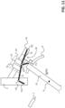
- Figure 17 shows the motion transmission mechanism 30 in the first configuration C1.
- the third hinge point H3 is in the first position P1, at which the movable arc contact 22 is in the coupled position P3 with the fixed arc contact 21.
- the third hinge point H3 is not aligned with the fixed hinge points H1, H2 and the lever elements 31, 32 are relatively positioned one to another, so that the motion transmission mechanism 30 does not exert any force on the contact shaft 24 solidly connected with the movable arc contact 22.
- first and second lever elements 31, 32 rotate according to opposite directions about the respective fixed hinge points H1, H2.
- the third hinge point H3 moves away from the first position P1 and it travels towards the second position P2 (direction D1).
- the motion transmission mechanism 30 starts exerting a force on the contact shaft 24, which is directed to decouple the movable arc contact 22 from the fixed arc contact21 .
- the movable arc contact 22 thus starts moving away (direction D3) from the fixed arc contact 21 notwithstanding the vacuum attraction force generated by the vacuum atmosphere in the vacuum chamber and, possibly, the compression force exerted by the compression spring coupled to the contact shaft 24.
- the third hinge point H3 passes through an intermediate deadlock position PD, which can be defined as a position of the third hinge point H3, in which this latter is aligned with the fixed hinge points H1 and H2 (with reference to figures 17 and 18 , the above-mentioned deadlock position PD lies on the line joining the fixed hinge points H1, H2).
- the movable arc contact 22 continues to move away from the fixed arc contact 21.
- the movable contact 10 decouples from the first lever portion 311 and stops actuating the first lever element 31.
- the third hinge point H3 reaches the second position P2 ( Figure 18 ) and the movable arc contact 22 reaches the uncoupled position P4 from the fixed arc contact 21, which is stably maintained due to the force exerted on the movable arc contact 22 by the motion transmission mechanism 30, which opposes to the vacuum attraction force generated by the vacuum atmosphere in the vacuum chamber and, possibly, the compression force exerted by the compression spring coupled to the contact shaft 24.
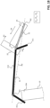
- Figure 18 shows the motion transmission mechanism 30 in the second configuration C2.
- the third hinge point H3 is in the second position P2, at which the movable arc contact 22 is in the uncoupled position P4 from the fixed arc contact 21.
- the third hinge point H3 is not aligned with the fixed hinge points H1, H2 and the lever elements 31, 32 are relatively positioned one to another, so that the motion transmission mechanism 30 exerts a force on the motion transmission element 24, which is directed to maintain the movable arc contact 22 uncoupled from the fixed arc contact 21.
- the third hinge point H3 moves away from the second position P2 and it travels towards the first position P1 (direction D2).
- the motion transmission mechanism 30 exerts a further force on the contact shaft 24, which is directed to decouple the movable arc contact 22 from the fixed arc contact 23.
- the movable arc contact 22 thus initially moves away from the fixed arc contact 21 (direction D3) notwithstanding the vacuum attraction force generated by the vacuum atmosphere in the vacuum chamber and, possibly, the compression force exerted by the compression spring coupled to the contact shaft 24.
- the movable arc contact 22 reaches the maximum distance from the fixed arc contact 21, when the third hinge axis H3 reaches the intermediate deadlock position PD, while moving away from the second position P2.
- the movable contact 10 decouples from the second lever portion 312 and stops actuating the first lever element 31.
- the motion transmission mechanism 30 stops exerting a force on the contact shaft 24 solidly connected with the movable arc contact 22.
- the movable arc contact 22 starts moving towards the fixed arc contact 21 (direction D4) due to the above-mentioned vacuum attraction force and spring compression force.
- the third hinge point H3 finally reaches the first position P1 ( Figure 17 ) and the movable arc contact 22 reaches the coupled position P3 with the fixed arc contact 21, which is stably maintained as the motion transmission mechanism 30 does not exert any force on the movable arc contact 22
- the switching apparatus 1 in operation, is capable of switching in three different operating states.
- the switching apparatus 1 can switch in:
- the switching apparatus 1 in operation, is capable of carrying out different type of manoeuvres, each corresponding to a transition among the above-mentioned operating states.
- the switching apparatus 1 is capable of carrying out:
- the switching apparatus 1 can switch from a closed state to a grounded state by carrying out an opening manoeuvre and subsequently a disconnecting manoeuvre while it can switch from a grounded state to a closed state by carrying out a reconnecting manoeuvre and subsequently a closing opening manoeuvre.
- the movable contact 10 of each electric pole is suitably driven according to the above-mentioned first rotation direction R1 or second rotation direction R2.
- the movable contact 10 moves according to the first rotation direction R1 during an opening manoeuvre or a disconnecting manoeuvre of the switching apparatus and it moves according to the second rotation direction R2 during a closing manoeuvre or a reconnecting manoeuvre of the switching apparatus.
- the movable contact 10 of each electric pole is reversibly movable between a first end-of-run position P A , which corresponds to a closed state of the switching apparatus, and a second end-of-run position P C , which corresponds to a grounded state of the switching apparatus.
- the movable contact 10 passes through an intermediate position P B , which corresponds to an open state of the switching apparatus, when it moves between the first and second end-of-run positions P A , P C .
- the movable contact 10 follows an arc-shaped trajectory when it moves between the first and second end-of-run positions P A , P C .
- each electric pole 2 When the switching apparatus is in a closed state, each electric pole 2 is in the operating condition illustrated in figure 1 ("single-disconnection" configuration) or figure 9 ("double-disconnection" configuration).
- each electric pole 2 has:
- the first lever portion 311 of the first lever element 31 is positioned along the motion trajectory of the first contact portion 10A of the movable contact 10 in such a way to be actuatable by this latter when it moves away towards the second intermediate position P B by rotating along the first rotation direction R1.
- the second lever portion 312 of the first lever element 31 is not positioned along the motion trajectory of the movable contact 10.
- a current can flow through the electric pole between the first and second pole terminals 11, 12 passing through the first fixed contact 5, the movable contact 10 and the second fixed contact 6. No currents can flow through the vacuum interrupter 20 as the fourth fixed contact 8 is electrically disconnected from the second fixed contact 6.
- each electric pole 2 When the switching apparatus is in an open state, each electric pole 2 is in the condition shown in figure 4 ("single-disconnection" configuration) or figure 12 ("double-disconnection" configuration).
- each electric pole 2 has:
- the first lever portion 311 of the first lever element 31 is not positioned along the motion trajectory of the movable contact 10.
- the second lever portion 312 of the first lever element 31 is positioned along the motion trajectory of the first contact portion 10A of the movable contact 10 in such a way to be actuatable by this latter when it moves towards the first end-of-run position P A by rotating along the second rotation direction R2.
- each electric pole 2 When the switching apparatus is in a grounded state, each electric pole 2 is in the condition illustrated in figure 8 ("single-disconnection" configuration) or figure 16 ("double-disconnection" configuration).
- each electric pole 2 has:
- the first lever portion 311 of the first lever element 31 is not positioned along the motion trajectory of the movable contact 10.
- the second lever portion 312 of the first lever element 31 is positioned along the motion trajectory of the first contact portion 10A of the movable contact 10 in such a way to be actuatable by this latter when it moves towards the first end-of-run position P A by rotating along the second rotation direction R2.
- the switching apparatus 1 carries out an opening manoeuvre, when it switches from the closed state to the open state.
- the movable contact 10 moves, according to the first rotation direction R1, between the first end-of-run position P A and the intermediate position P B .
- the movable contact 10 thus moves away from the corresponding first fixed contact 5.
- the movable contact 10 When the movable contact 10 starts moving according to the first rotation direction R1, the movable contact 10 couples to the fourth fixed contact 8 (at the movable contact portion 10A). The movable contact 10 remains coupled to the second fixed contact 6. In this way, the movable contact 10 electrically connects also the fourth fixed contact 8 with the second fixed contact 6 ( figures 2 and 10 ).
- the first and fourth fixed contacts 5 and 8 are mutually positioned so that the movable contact 10 couples with the fourth fixed contact 8 before decoupling from the first fixed contact 5.
- both the first fixed contact 5 and the fourth fixed contact 8 are electrically connected with the second fixed contact 6.
- a current can flow between the first and second pole terminals 11, 12 passing through the first fixed contact 5 and the vacuum interrupter 20 in parallel. Obviously, most of the current will flow along the first fixed contact 5 as the current path passing through this electric contact has a lower equivalent resistance with respect to the current path passing through the vacuum interrupter.
- the movable contact 10 When it finally decouples from the first fixed contact 5, the movable contact 10 electrically disconnects the first fixed contact 5 from the second fixed contact 6. In this situation, a current flowing along the electric pole is fully deviated through the vacuum interrupter 20 as no current can flow through the first fixed contact 5. The formation of electric arcs at the movable contact 10 is thus prevented.
- the movable contact 10 does not interact with the second lever portion 312 of the first lever element 31 as this latter is not positioned along the motion trajectory of the movable contact 10.
- the motion transmission mechanism thus initially maintains the first configuration C1 and the movable arc contact 21 remains initially coupled with the fixed arc contact 21.
- the movable contact 10 couples to the first lever portion 311 and actuates the first lever element 31 while remaining slidingly coupled to the fourth fixed contact 8 ( figures 3 and 11 ).
- the actuation of the first lever element 31 by the movable contact 10 causes a transition of the motion transmission mechanism 30 from the first configuration C1 to the second configuration C2 and a consequent movement D3 of the movable arc contact 22 from the coupled position P3 with the fixed arc contact 21 to the uncoupled position P4 from the fixed arc contact 21.
- the separation of the electric contacts 21, 22 causes the rising of electric arcs between said electric contacts.
- the electric contacts 21, 22 are immersed in a vacuum atmosphere, such electric arcs can be quenched efficiently, thereby quickly leading to the interruption of the current flowing along the electric pole.
- the movable contact 10 Upon a further movement towards the intermediate position P B , according to the first rotation direction R1, the movable contact 10 decouples from the motion transmission mechanism 30, which remains in the second configuration C2, and from the fourth fixed contact 8, thereby electrically disconnecting this latter from the second fixed contact 6.
- the movable contact 10 remains coupled to the second fixed contact 6.
- the movable contact 10 decouples also from the second fixed contact 6.
- the movable contact 10 then reaches the intermediate position P B , which corresponds to an open state of the switching apparatus ( figures 4 and 12 ).
- the switching apparatus 1 carries out a closing manoeuvre, when it switches from the open state to the close state.
- the switching apparatus Before carrying out a closing manoeuvre, the switching apparatus may have carried out a reconnecting manoeuvre in order to switch in an open state.
- the movable contact 10 moves, according to the second rotation direction R2, between the intermediate position P B and the first end-of-run position P A .
- the movable contact 10 thus moves towards the corresponding first fixed contact 5 ( figures 5 and 12 ).
- the movable contact 10 couples with the fourth fixed contact 8 (at the first contact portion 10A), thereby electrically connecting the fourth fixed contact 8 with the second fixed contact 6.
- the movable contact 10 is already coupled to the second fixed contact 6.
- the movable contact 10 couples also to the second fixed contact 6.
- the movable contact 10 does not interact with the motion transmission mechanism 30 as this latter is still in the second configuration C2 ( figures 6 and 14 ) and the first lever portion 311 of the first lever element 31 is not positioned along the motion trajectory of the movable contact 10.
- the motion transmission mechanism thus maintains the second configuration C2 and the movable arc contact 21 remains decoupled from the fixed arc contact 21.
- the movable contact 10 couples to the first fixed contact 5 (at the movable contact portion 10A) while remaining coupled to the second fixed contact 6. In this way, the movable contact 10 electrically connects the first fixed contact 5 with the second fixed contact 6.
- the first and fourth fixed contacts 5 and 8 are mutually positioned so that the movable contact 10 couples with the first fixed contact 5 before decoupling from the fourth fixed contact 8.
- both the first fixed contact 5 and the fourth fixed contact 8 are electrically connected with the second fixed contact 6.
- the movable contact 10 When it finally decouples from the fourth fixed contact 8, the movable contact 10 electrically disconnects the fourth fixed contact 8 from the second fixed contact 6.
- the movable contact 10 couples to the second lever portion 312 and it actuates the first lever element 31 while remaining coupled to the first fixed contact 5 ( figures 7 and 15 ) and to the second fixed contact 6.
- the actuation of the first lever element 31 by the movable contact 10 causes a transition of the motion transmission mechanism 30 from the second configuration C2 to the first configuration C1 and a consequent movement D4 of the movable arc contact 22 from the uncoupled position P4 from the fixed arc contact 21 to the coupled position P3 with the fixed arc contact 21.
- the movable contact 10 then reaches the first end-of-run position P A , which corresponds to a closed state of the switching apparatus ( figures 1 and 9 ).
- the switching apparatus 1 carries out a disconnecting manoeuvre, when it switches from an open state to a grounded state.
- the switching apparatus Before carrying out a disconnecting manoeuvre, the switching apparatus has to carry out an opening manoeuvre as described above in order to switch in an open state.
- the movable contact 10 moves, according to the first rotation direction R1, between the intermediate position P B and the second end-of-run position P C .
- the movable contact 10 couples with the third fixed contact 7 at the first movable contact portion 10A, when it reaches the second end-of-run position P C ., while it has the second movable contact portion 10B already coupled to the second fixed contact 6.
- the movable contact 10 couples also to the second fixed contact 6 at the first movable contact portion 10A and it couples with the third fixed contact 7 at the second movable contact portion 10B.
- the movable contact 10 electrically connects the second pole terminal 12 with the ground terminal 13.
- the second pole terminal 12 is therefore put at a ground voltage.
- the switching apparatus 1 carries out a reconnecting manoeuvre, when it switches from a grounded state to an open state.
- the movable contact 10 moves, according to the second rotation direction R2, between the second end-of-run position P C and the intermediate position P B .
- the movable contact 10 remains coupled to the second fixed contact 6.
- the movable contact 10 decouples also from the second fixed contact 6.
- the movable contact 10 electrically disconnects the third fixed contact 7 from the second fixed contact 6.
- the movable contact 10 does not electrically connect the second pole terminal 12 with the ground terminal 13 anymore.
- the second pole terminal 12 results therefore at a floating voltage. It is evidenced that the motion transmission mechanism 30 remains in the second configuration C2, when the switching apparatus carries out a reconnecting manoeuvre.
- the movable arc contact 21 thus remains decoupled from the fixed arc contact 21.
- the switching apparatus provides remarkable advantages with respect to the known apparatuses of the state of the art.
- the switching apparatus of the invention includes, for each electric pole, a bistable motion transmission mechanism 30, which allows the movable contact 10 to drive the separation of the movable arc contact 22 from the fixed arc contact 21 depending on the position reached during an opening manoeuvre of the switching apparatus.
- the switching apparatus of the invention has electric poles with a very compact, simple and robust structure with relevant benefits in terms of size optimization.
- the switching apparatus ensures high-level performances in terms of dielectric insulation and arc-quenching capabilities during the current breaking process and, at the same time, it is characterised by high levels of reliability for the intended applications.
- the switching apparatus, according to the invention is of relatively easy and cheap industrial production and installation on the field.
Landscapes
- Arc-Extinguishing Devices That Are Switches (AREA)
- Driving Mechanisms And Operating Circuits Of Arc-Extinguishing High-Tension Switches (AREA)
- Rotary Switch, Piano Key Switch, And Lever Switch (AREA)
Claims (17)
- Appareil de commutation (1) pour des systèmes électriques moyenne tension, ledit appareil de commutation comprenant un ou plusieurs pôles électriques (2), pour chaque pôle électrique, ledit appareil de commutation comprenant :- une première borne (11) de pôle, une seconde borne (12) de pôle et une borne (13) de terre, ladite première borne (11) de pôle pouvant être couplée électriquement avec un premier conducteur d'une ligne électrique, ladite seconde borne (12) de pôle pouvant être couplée électriquement à un second conducteur de ladite ligne électrique et ladite borne (13) de terre pouvant être couplée électriquement à un conducteur de terre ;- une pluralité de contacts fixes espacés les uns des autres, ladite pluralité de contacts fixes comprenant un premier contact fixe (5) connecté électriquement à ladite première borne (11) de pôle, un deuxième contact fixe (6) connecté électriquement à ladite seconde borne (12) de pôle, un troisième contact fixe (7) connecté électriquement à ladite borne (13) de terre et un quatrième contact fixe (8) ;- un contact mobile (10) mobile de manière réversible autour d'un axe de rotation (A1) correspondant selon des premier et second sens de rotation (R1, R2) opposés, de sorte que ledit contact mobile peut être couplé auxdits contacts fixes (5, 6, 7, 8) ou découplé de ceux-ci ;- un interrupteur à vide (20) comprenant un contact d'arc fixe (21) connecté électriquement à ladite première borne (11) de pôle, un contact d'arc mobile (22) connecté électriquement audit quatrième contact fixe (8) et mobile de manière réversible le long d'un axe de translation correspondant (A) entre une position couplée (P3) avec ledit contact d'arc fixe (21) et une position non couplée (P4) dudit contact d'arc fixe (21) et une chambre à vide (23), dans lequel ledit contact d'arc fixe (21) et ledit contact d'arc mobile (22) sont enfermés et peuvent être couplés ou découplés ;- un mécanisme de transmission de mouvement (30) couplé fonctionnellement audit contact d'arc mobile (22), ledit mécanisme de transmission de mouvement pouvant être actionné par ledit contact mobile (10) pour entraîner un mouvement dudit contact d'arc mobile (22) le long dudit axe de translation (A), lorsque ledit contact mobile se déplace autour dudit axe de rotation (A1) ;caractérisé en ce que ledit mécanisme de transmission de mouvement (30) comprend un premier élément levier (31) pivotant sur un support fixe (5) au niveau d'un premier point d'articulation (H1) et un second élément levier (32) pivotant sur un dit contact d'arc mobile (22) au niveau d'un second point d'articulation (H2), lesdits premier et second éléments leviers (31, 32) pivotant l'un sur l'autre au niveau d'un troisième point d'articulation (H3).
- Appareil de commutation, selon la revendication 1, caractérisé en ce que ledit mécanisme de transmission de mouvement (30) est configuré pour prendre une première configuration (C1), à laquelle ledit troisième point d'articulation (H3) est dans une première position (P1) et ledit contact d'arc mobile (22) est dans ladite position couplée (P3), et une seconde configuration (C2), à laquelle ledit troisième point d'articulation (H3) est dans une seconde position (P2), espacée de ladite première position (P1), et ledit contact d'arc mobile (22) est dans ladite position découplée (P4),ledit mécanisme de transmission de mouvement (30) étant configuré pour maintenir de manière stable ladite première configuration (C1) ou ladite seconde configuration (C2), si ledit mécanisme de transmission de mouvement n'est pas actionné par ledit contact mobile (10),ledit mécanisme de transmission de mouvement (30) étant configuré pour changer de configuration, si ledit mécanisme de transmission de mouvement est actionné par ledit contact mobile (10).
- Appareil de commutation, selon la revendication 2, caractérisé en ce que ledit mécanisme de transmission de mouvement (30) est configuré pour passer de ladite première configuration (C1) à ladite seconde configuration (C2) lors d'un actionnement par ledit contact mobile (10), lorsque ledit contact mobile se déplace selon ledit premier sens de rotation (R1) et connecte électriquement ledit quatrième contact fixe (8) audit deuxième contact fixe (6), une transition dudit mécanisme de transmission de mouvement de ladite première configuration (C1) à ladite seconde configuration (C2) entraînant un mouvement dudit contact d'arc mobile (22) de ladite position couplée (P3) à ladite position découplée (P4).
- Appareil de commutation, selon l'une des revendications 2 à 3, caractérisé en ce que ledit mécanisme de transmission de mouvement (30) est configuré pour passer de ladite seconde configuration (C2) à ladite première configuration (C1) lors d'un actionnement par ledit contact mobile (10), lorsque ledit contact mobile se déplace selon ledit second sens de rotation (R2) et connecte électriquement ledit premier contact fixe (5) audit deuxième contact fixe (6), une transition dudit mécanisme de transmission de mouvement de ladite seconde configuration (C2) à ladite première configuration (C1) entraînant un mouvement dudit contact d'arc mobile (22) de ladite position découplée (P4) à ladite position couplée (P3).
- Appareil de commutation, selon l'une des revendications 2 à 4, caractérisé en ce que ledit mécanisme de transmission de mouvement (30) est configuré pour passer de ladite première configuration (C1) à ladite seconde configuration (C2) ou de ladite seconde configuration (C2) à ladite première configuration (C1), lors d'un actionnement dudit premier élément levier (31) par ledit contact mobile (10).
- Appareil de commutation, selon la revendication 5, caractérisé en ce que ledit premier élément levier comprend une première partie de levier (311) et une seconde partie de levier (312), qui sont espacées l'une de l'autre,ledit mécanisme de transmission de mouvement (30) étant configuré pour passer de ladite première configuration (C1) à ladite seconde configuration (C2), lors d'un actionnement de ladite première partie de levier (311) par ledit contact mobile (10),ledit mécanisme de transmission de mouvement (30) étant configuré pour passer de ladite seconde configuration (C2) à ladite première configuration (C1), lors d'un actionnement de ladite seconde partie de levier (312) par ledit contact mobile (10).
- Appareil de commutation, selon l'une ou plusieurs des revendications précédentes, caractérisé en ce que le premier contact mobile (10) de chaque pôle électrique est mobile de manière réversible entre une première position de fin de course (PA), qui correspond à un état fermé dudit appareil de commutation, et une seconde position de fin de course (PC), qui correspond à un état de mise à la terre dudit appareil de commutation, ledit contact mobile passant par une position intermédiaire (PB), qui correspond à un état ouvert dudit appareil de commutation, lorsqu'il se déplace entre lesdites première et seconde positions de fin de course (PA, PC).
- Appareil de commutation, selon la revendication 7, caractérisé en ce que, pendant une manœuvre d'ouverture dudit appareil de commutation, ledit contact mobile (10) se déplace selon ledit premier sens de rotation (R1) en s'éloignant de ladite première position de fin de course (PA) et vers ladite position intermédiaire (PB), lors d'un mouvement initial selon ledit premier sens de rotation (R1), ledit contact mobile (10) se découplant dudit premier contact fixe (5) et se couplant audit quatrième contact fixe (8), déconnectant ainsi électriquement ledit premier contact fixe (5) dudit deuxième contact fixe (6) et connectant électriquement ledit quatrième contact fixe (8) audit deuxième contact fixe (6).
- Appareil de commutation, selon la revendication 8, caractérisé en ce que ledit contact mobile (10) actionne ledit mécanisme de transmission de mouvement (30) tandis que ledit contact mobile est couplé de manière coulissante audit quatrième contact fixe (8) et connecte électriquement ledit quatrième contact fixe (6) audit deuxième contact fixe (6), l'actionnement par ledit contact mobile (10) entraînant une transition dudit mécanisme de transmission de mouvement (30) de ladite première configuration (C1) à ladite seconde configuration (C2) et un mouvement résultant dudit contact d'arc mobile (22) de ladite position couplée (P3) à ladite position découplée (P4).
- Appareil de commutation, selon la revendication 9, caractérisé en ce que, lors d'un autre mouvement selon ledit premier sens de rotation (R1), ledit contact mobile (10) se découple dudit mécanisme de transmission de mouvement (30) et dudit quatrième contact fixe (8) et atteint ensuite ladite position intermédiaire (PB), déconnectant ainsi électriquement ledit quatrième contact fixe (8) dudit deuxième contact fixe (6).
- Appareil de commutation, selon l'une des revendications 7 à 10, caractérisé en ce que, pendant une manœuvre de fermeture dudit appareil de commutation, ledit contact mobile (10) se déplace selon ledit second sens de rotation (R2) en s'éloignant de ladite position intermédiaire (PB) et vers ladite première position de fin de course (PA), lors d'un mouvement initial selon ledit second sens de rotation (R2), ledit contact mobile (10) se couplant audit quatrième contact fixe (8), connectant ainsi électriquement ledit quatrième contact fixe (8) audit deuxième contact fixe (6).
- Appareil de commutation, selon la revendication 11, caractérisé en ce que, lors d'un autre mouvement selon ledit second sens de rotation (R2), ledit contact mobile (10) se découple dudit quatrième contact fixe (8) et se couple audit premier contact fixe (5), déconnectant ainsi électriquement ledit quatrième contact fixe (8) dudit deuxième contact fixe (6) et connectant électriquement ledit premier contact fixe (5) audit deuxième contact fixe (6).
- Appareil de commutation, selon la revendication 12, caractérisé en ce que, lors d'un autre mouvement selon ledit second sens de rotation (R2), ledit contact mobile (10) actionne ledit mécanisme de transmission de mouvement (30) tandis que ledit contact mobile est couplé de manière coulissante audit premier contact fixe (5) et connecte électriquement ledit premier contact fixe (5) audit deuxième contact fixe (6), l'actionnement par ledit contact mobile (10) entraînant une transition dudit mécanisme de transmission de mouvement de ladite seconde configuration (C2) à ladite première configuration (C1) et un mouvement résultant dudit contact d'arc mobile (22) de ladite position découplée (P4) à ladite position couplée (P3).
- Appareil de commutation, selon la revendication 13, caractérisé en ce que, lors d'un autre mouvement selon ledit second sens de rotation (R2), ledit contact mobile (10) se découple dudit mécanisme de transmission de mouvement (30) et atteint ensuite ladite première position de fin de course (PA), tout en restant couplé de manière coulissante audit premier contact fixe (5) et en connectant électriquement ledit premier contact fixe (5) audit deuxième contact fixe (6).
- Appareil de commutation, selon l'une ou plusieurs des revendications précédentes, caractérisé en ce que le contact mobile (10) de chaque pôle électrique comprend un corps conducteur ayant une première partie (10A) de contact mobile qui peut être couplée auxdits premier, troisième et quatrième contacts fixes (5, 7, 8) ou découplée de ceux-ci et une seconde partie (10B) de contact mobile qui est électriquement connectée audit deuxième contact fixe (6).
- Appareil de commutation, selon l'une des revendications 1 à 14, caractérisé en ce que le contact mobile (10) de chaque pôle électrique comprend un corps conducteur ayant une première partie (10A) de contact mobile qui peut être couplée auxdits premier, deuxième et quatrième contacts fixes (5, 6, 8) ou découplée de ceux-ci et une deuxième partie (10B) de contact mobile qui peut être couplée auxdits deuxième et troisième contacts fixes (6, 7) ou découplée de ceux-ci.
- Appareil de commutation, selon l'une des revendications précédentes, caractérisé en ce qu'il s'agit d'un interrupteur coupe-charge pour des systèmes électriques moyenne tension.
Priority Applications (5)
| Application Number | Priority Date | Filing Date | Title |
|---|---|---|---|
| ES22173028T ES3034242T3 (en) | 2022-05-12 | 2022-05-12 | A medium voltage switching apparatus |
| EP22173028.6A EP4276874B1 (fr) | 2022-05-12 | 2022-05-12 | Appareil de commutation moyenne tension |
| CA3195375A CA3195375A1 (fr) | 2022-05-12 | 2023-04-06 | Appareil de commutation de tension moyenne |
| US18/306,473 US12293888B2 (en) | 2022-05-12 | 2023-04-25 | Medium voltage switching apparatus |
| CN202310528647.0A CN117059438A (zh) | 2022-05-12 | 2023-05-11 | 中压开关装置 |
Applications Claiming Priority (1)
| Application Number | Priority Date | Filing Date | Title |
|---|---|---|---|
| EP22173028.6A EP4276874B1 (fr) | 2022-05-12 | 2022-05-12 | Appareil de commutation moyenne tension |
Publications (2)
| Publication Number | Publication Date |
|---|---|
| EP4276874A1 EP4276874A1 (fr) | 2023-11-15 |
| EP4276874B1 true EP4276874B1 (fr) | 2025-04-30 |
Family
ID=81648344
Family Applications (1)
| Application Number | Title | Priority Date | Filing Date |
|---|---|---|---|
| EP22173028.6A Active EP4276874B1 (fr) | 2022-05-12 | 2022-05-12 | Appareil de commutation moyenne tension |
Country Status (5)
| Country | Link |
|---|---|
| US (1) | US12293888B2 (fr) |
| EP (1) | EP4276874B1 (fr) |
| CN (1) | CN117059438A (fr) |
| CA (1) | CA3195375A1 (fr) |
| ES (1) | ES3034242T3 (fr) |
Family Cites Families (18)
| Publication number | Priority date | Publication date | Assignee | Title |
|---|---|---|---|---|
| US2480622A (en) | 1945-12-04 | 1949-08-30 | Gen Electric | Electric switch |
| US2773154A (en) * | 1955-09-19 | 1956-12-04 | Gen Electric | Electric switch |
| US3671696A (en) * | 1970-11-16 | 1972-06-20 | Allis Chalmers Mfg Co | Vacuum interrupter shunted with mechanical switch |
| US3824359A (en) * | 1972-10-06 | 1974-07-16 | Mc Graw Edison Co | Vacuum loadbreak switch |
| FR2719154B1 (fr) | 1994-04-25 | 1996-06-07 | Merlin Gerin | Interrupteur électrique moyenne tension. |
| FR2722912B1 (fr) | 1994-07-20 | 1996-09-13 | Schneider Electric Sa | Interrupteurs electriques moyenne tension |
| FR2817655B1 (fr) * | 2000-12-01 | 2003-09-26 | Alstom | Dispositif de securite applique a l'embrochage et au debrochage d'un fusible dans un appareillage electrique moyenne tension |
| DE102005002139B4 (de) | 2005-01-13 | 2007-01-25 | Siemens Ag | Dreistellungsschalter mit Kurvenscheibe |
| FR2937786B1 (fr) | 2008-10-29 | 2010-12-24 | Areva T & D Sa | Interrupteur de courant sur une ligne electrique comprenant une ampoule a vide |
| FR2946180B1 (fr) * | 2009-05-26 | 2012-12-14 | Areva T & D Sa | Dispositif d'accrochage et de verrouillage interne a un interrupteur ou a un disjoncteur. |
| DE202010009448U1 (de) | 2010-06-23 | 2010-09-09 | Ipt International Power & Technology Gmbh | Hochspannungsschaltvorrichtung |
| FR2970809B1 (fr) * | 2011-01-25 | 2013-02-22 | Schneider Electric Ind Sas | Dispositif de coupure moyenne tension comprenant une ampoule a vide |
| US8729985B2 (en) * | 2012-01-23 | 2014-05-20 | Electro-Mechanical Corporation | Switchgear visible disconnect mechanical interlock |
| EP2845213B1 (fr) | 2012-06-25 | 2016-08-03 | Siemens Aktiengesellschaft | Sectionneur à coupure sous charge à trois positions pour installations électriques moyenne tension |
| CN104319166B (zh) | 2014-11-12 | 2016-05-18 | 沈阳华德海泰电器有限公司 | 一种采用连接母排实现负载侧外接地的三工位真空开关 |
| US9679724B2 (en) * | 2015-07-13 | 2017-06-13 | Eaton Corporation | Component for electric power system, and contact assembly and open air arcing elimination method therefor |
| ES2943936T3 (es) * | 2019-03-29 | 2023-06-16 | Siemens Ag | Interruptor de tres posiciones optimizado |
| ES2888700B2 (es) * | 2020-06-25 | 2022-05-18 | Ormazabal Corporate Tech A I E | Interruptor de corte en carga o de corrientes de cortocircuito |
-
2022
- 2022-05-12 EP EP22173028.6A patent/EP4276874B1/fr active Active
- 2022-05-12 ES ES22173028T patent/ES3034242T3/es active Active
-
2023
- 2023-04-06 CA CA3195375A patent/CA3195375A1/fr active Pending
- 2023-04-25 US US18/306,473 patent/US12293888B2/en active Active
- 2023-05-11 CN CN202310528647.0A patent/CN117059438A/zh active Pending
Also Published As
| Publication number | Publication date |
|---|---|
| CN117059438A (zh) | 2023-11-14 |
| EP4276874A1 (fr) | 2023-11-15 |
| ES3034242T3 (en) | 2025-08-14 |
| CA3195375A1 (fr) | 2023-11-12 |
| US20230368992A1 (en) | 2023-11-16 |
| US12293888B2 (en) | 2025-05-06 |
Similar Documents
| Publication | Publication Date | Title |
|---|---|---|
| US11776779B2 (en) | Medium voltage switching apparatus | |
| US11715613B2 (en) | Medium voltage switching apparatus | |
| US12444559B2 (en) | Medium voltage switching apparatus | |
| EP4276872B1 (fr) | Appareil de commutation moyenne tension | |
| EP4276869A1 (fr) | Appareil de commutation moyenne tension | |
| EP4283645B1 (fr) | Appareil de commutation moyenne tension | |
| US12387890B2 (en) | Medium voltage switching apparatus | |
| EP4276874B1 (fr) | Appareil de commutation moyenne tension | |
| EP4277059A1 (fr) | Équipement de commutation pour réseaux de distribution d'énergie électrique | |
| US20250372324A1 (en) | Medium voltage switching apparatus | |
| EP3093866B1 (fr) | Unité de pôle électrique pour disjoncteurs à isolation gazeuse moyenne tension | |
| EP4089704B1 (fr) | Appareil de commutation moyenne tension | |
| EP4030455A1 (fr) | Appareil de commutation moyenne tension | |
| EP4089705A1 (fr) | Appareil de commutation moyenne tension | |
| JP4693736B2 (ja) | ガス絶縁断路器 |
Legal Events
| Date | Code | Title | Description |
|---|---|---|---|
| PUAI | Public reference made under article 153(3) epc to a published international application that has entered the european phase |
Free format text: ORIGINAL CODE: 0009012 |
|
| STAA | Information on the status of an ep patent application or granted ep patent |
Free format text: STATUS: THE APPLICATION HAS BEEN PUBLISHED |
|
| AK | Designated contracting states |
Kind code of ref document: A1 Designated state(s): AL AT BE BG CH CY CZ DE DK EE ES FI FR GB GR HR HU IE IS IT LI LT LU LV MC MK MT NL NO PL PT RO RS SE SI SK SM TR |
|
| STAA | Information on the status of an ep patent application or granted ep patent |
Free format text: STATUS: REQUEST FOR EXAMINATION WAS MADE |
|
| 17P | Request for examination filed |
Effective date: 20240223 |
|
| RBV | Designated contracting states (corrected) |
Designated state(s): AL AT BE BG CH CY CZ DE DK EE ES FI FR GB GR HR HU IE IS IT LI LT LU LV MC MK MT NL NO PL PT RO RS SE SI SK SM TR |
|
| GRAP | Despatch of communication of intention to grant a patent |
Free format text: ORIGINAL CODE: EPIDOSNIGR1 |
|
| STAA | Information on the status of an ep patent application or granted ep patent |
Free format text: STATUS: GRANT OF PATENT IS INTENDED |
|
| RIC1 | Information provided on ipc code assigned before grant |
Ipc: H01H 33/666 20060101AFI20240612BHEP |
|
| INTG | Intention to grant announced |
Effective date: 20240627 |
|
| GRAJ | Information related to disapproval of communication of intention to grant by the applicant or resumption of examination proceedings by the epo deleted |
Free format text: ORIGINAL CODE: EPIDOSDIGR1 |
|
| STAA | Information on the status of an ep patent application or granted ep patent |
Free format text: STATUS: REQUEST FOR EXAMINATION WAS MADE |
|
| STAA | Information on the status of an ep patent application or granted ep patent |
Free format text: STATUS: EXAMINATION IS IN PROGRESS |
|
| 17Q | First examination report despatched |
Effective date: 20241011 |
|
| INTC | Intention to grant announced (deleted) | ||
| GRAP | Despatch of communication of intention to grant a patent |
Free format text: ORIGINAL CODE: EPIDOSNIGR1 |
|
| STAA | Information on the status of an ep patent application or granted ep patent |
Free format text: STATUS: GRANT OF PATENT IS INTENDED |
|
| INTG | Intention to grant announced |
Effective date: 20250131 |
|
| GRAS | Grant fee paid |
Free format text: ORIGINAL CODE: EPIDOSNIGR3 |
|
| GRAA | (expected) grant |
Free format text: ORIGINAL CODE: 0009210 |
|
| STAA | Information on the status of an ep patent application or granted ep patent |
Free format text: STATUS: THE PATENT HAS BEEN GRANTED |
|
| AK | Designated contracting states |
Kind code of ref document: B1 Designated state(s): AL AT BE BG CH CY CZ DE DK EE ES FI FR GB GR HR HU IE IS IT LI LT LU LV MC MK MT NL NO PL PT RO RS SE SI SK SM TR |
|
| REG | Reference to a national code |
Ref country code: CH Ref legal event code: EP Ref country code: GB Ref legal event code: FG4D |
|
| REG | Reference to a national code |
Ref country code: IE Ref legal event code: FG4D |
|
| REG | Reference to a national code |
Ref country code: DE Ref legal event code: R096 Ref document number: 602022013769 Country of ref document: DE |
|
| PGFP | Annual fee paid to national office [announced via postgrant information from national office to epo] |
Ref country code: DE Payment date: 20250521 Year of fee payment: 4 |
|
| PGFP | Annual fee paid to national office [announced via postgrant information from national office to epo] |
Ref country code: FR Payment date: 20250627 Year of fee payment: 4 |
|
| PGFP | Annual fee paid to national office [announced via postgrant information from national office to epo] |
Ref country code: AT Payment date: 20250721 Year of fee payment: 4 |
|
| REG | Reference to a national code |
Ref country code: ES Ref legal event code: FG2A Ref document number: 3034242 Country of ref document: ES Kind code of ref document: T3 Effective date: 20250814 |
|
| REG | Reference to a national code |
Ref country code: NL Ref legal event code: MP Effective date: 20250430 |
|
| REG | Reference to a national code |
Ref country code: AT Ref legal event code: MK05 Ref document number: 1790876 Country of ref document: AT Kind code of ref document: T Effective date: 20250430 |
|
| PG25 | Lapsed in a contracting state [announced via postgrant information from national office to epo] |
Ref country code: PT Free format text: LAPSE BECAUSE OF FAILURE TO SUBMIT A TRANSLATION OF THE DESCRIPTION OR TO PAY THE FEE WITHIN THE PRESCRIBED TIME-LIMIT Effective date: 20250901 Ref country code: FI Free format text: LAPSE BECAUSE OF FAILURE TO SUBMIT A TRANSLATION OF THE DESCRIPTION OR TO PAY THE FEE WITHIN THE PRESCRIBED TIME-LIMIT Effective date: 20250430 |
|
| PGFP | Annual fee paid to national office [announced via postgrant information from national office to epo] |
Ref country code: ES Payment date: 20250630 Year of fee payment: 4 |
|
| REG | Reference to a national code |
Ref country code: LT Ref legal event code: MG9D |
|
| PG25 | Lapsed in a contracting state [announced via postgrant information from national office to epo] |
Ref country code: GR Free format text: LAPSE BECAUSE OF FAILURE TO SUBMIT A TRANSLATION OF THE DESCRIPTION OR TO PAY THE FEE WITHIN THE PRESCRIBED TIME-LIMIT Effective date: 20250731 |
|
| PGFP | Annual fee paid to national office [announced via postgrant information from national office to epo] |
Ref country code: NO Payment date: 20250523 Year of fee payment: 4 |
|
| PG25 | Lapsed in a contracting state [announced via postgrant information from national office to epo] |
Ref country code: PL Free format text: LAPSE BECAUSE OF FAILURE TO SUBMIT A TRANSLATION OF THE DESCRIPTION OR TO PAY THE FEE WITHIN THE PRESCRIBED TIME-LIMIT Effective date: 20250430 Ref country code: NL Free format text: LAPSE BECAUSE OF FAILURE TO SUBMIT A TRANSLATION OF THE DESCRIPTION OR TO PAY THE FEE WITHIN THE PRESCRIBED TIME-LIMIT Effective date: 20250430 |
|
| PGFP | Annual fee paid to national office [announced via postgrant information from national office to epo] |
Ref country code: IT Payment date: 20250531 Year of fee payment: 4 |
|
| PG25 | Lapsed in a contracting state [announced via postgrant information from national office to epo] |
Ref country code: BG Free format text: LAPSE BECAUSE OF FAILURE TO SUBMIT A TRANSLATION OF THE DESCRIPTION OR TO PAY THE FEE WITHIN THE PRESCRIBED TIME-LIMIT Effective date: 20250430 |
|
| PG25 | Lapsed in a contracting state [announced via postgrant information from national office to epo] |
Ref country code: HR Free format text: LAPSE BECAUSE OF FAILURE TO SUBMIT A TRANSLATION OF THE DESCRIPTION OR TO PAY THE FEE WITHIN THE PRESCRIBED TIME-LIMIT Effective date: 20250430 Ref country code: AT Free format text: LAPSE BECAUSE OF FAILURE TO SUBMIT A TRANSLATION OF THE DESCRIPTION OR TO PAY THE FEE WITHIN THE PRESCRIBED TIME-LIMIT Effective date: 20250430 |
|
| PG25 | Lapsed in a contracting state [announced via postgrant information from national office to epo] |
Ref country code: RS Free format text: LAPSE BECAUSE OF FAILURE TO SUBMIT A TRANSLATION OF THE DESCRIPTION OR TO PAY THE FEE WITHIN THE PRESCRIBED TIME-LIMIT Effective date: 20250731 |
|
| PG25 | Lapsed in a contracting state [announced via postgrant information from national office to epo] |
Ref country code: IS Free format text: LAPSE BECAUSE OF FAILURE TO SUBMIT A TRANSLATION OF THE DESCRIPTION OR TO PAY THE FEE WITHIN THE PRESCRIBED TIME-LIMIT Effective date: 20250830 |
|
| PG25 | Lapsed in a contracting state [announced via postgrant information from national office to epo] |
Ref country code: LV Free format text: LAPSE BECAUSE OF FAILURE TO SUBMIT A TRANSLATION OF THE DESCRIPTION OR TO PAY THE FEE WITHIN THE PRESCRIBED TIME-LIMIT Effective date: 20250430 |
|
| REG | Reference to a national code |
Ref country code: CH Ref legal event code: H13 Free format text: ST27 STATUS EVENT CODE: U-0-0-H10-H13 (AS PROVIDED BY THE NATIONAL OFFICE) Effective date: 20251223 |
|
| PG25 | Lapsed in a contracting state [announced via postgrant information from national office to epo] |
Ref country code: SM Free format text: LAPSE BECAUSE OF FAILURE TO SUBMIT A TRANSLATION OF THE DESCRIPTION OR TO PAY THE FEE WITHIN THE PRESCRIBED TIME-LIMIT Effective date: 20250430 Ref country code: DK Free format text: LAPSE BECAUSE OF FAILURE TO SUBMIT A TRANSLATION OF THE DESCRIPTION OR TO PAY THE FEE WITHIN THE PRESCRIBED TIME-LIMIT Effective date: 20250430 |
|
| PG25 | Lapsed in a contracting state [announced via postgrant information from national office to epo] |
Ref country code: LU Free format text: LAPSE BECAUSE OF NON-PAYMENT OF DUE FEES Effective date: 20250512 |
|
| PG25 | Lapsed in a contracting state [announced via postgrant information from national office to epo] |
Ref country code: CH Free format text: LAPSE BECAUSE OF NON-PAYMENT OF DUE FEES Effective date: 20250531 |
|
| PG25 | Lapsed in a contracting state [announced via postgrant information from national office to epo] |
Ref country code: CZ Free format text: LAPSE BECAUSE OF FAILURE TO SUBMIT A TRANSLATION OF THE DESCRIPTION OR TO PAY THE FEE WITHIN THE PRESCRIBED TIME-LIMIT Effective date: 20250430 |
|
| PG25 | Lapsed in a contracting state [announced via postgrant information from national office to epo] |
Ref country code: EE Free format text: LAPSE BECAUSE OF FAILURE TO SUBMIT A TRANSLATION OF THE DESCRIPTION OR TO PAY THE FEE WITHIN THE PRESCRIBED TIME-LIMIT Effective date: 20250430 |
|
| PG25 | Lapsed in a contracting state [announced via postgrant information from national office to epo] |
Ref country code: SK Free format text: LAPSE BECAUSE OF FAILURE TO SUBMIT A TRANSLATION OF THE DESCRIPTION OR TO PAY THE FEE WITHIN THE PRESCRIBED TIME-LIMIT Effective date: 20250430 |
|
| REG | Reference to a national code |
Ref country code: BE Ref legal event code: MM Effective date: 20250531 |
|
| PG25 | Lapsed in a contracting state [announced via postgrant information from national office to epo] |
Ref country code: MC Free format text: LAPSE BECAUSE OF FAILURE TO SUBMIT A TRANSLATION OF THE DESCRIPTION OR TO PAY THE FEE WITHIN THE PRESCRIBED TIME-LIMIT Effective date: 20250430 |
|
| REG | Reference to a national code |
Ref country code: DE Ref legal event code: R097 Ref document number: 602022013769 Country of ref document: DE |
|
| PG25 | Lapsed in a contracting state [announced via postgrant information from national office to epo] |
Ref country code: RO Free format text: LAPSE BECAUSE OF FAILURE TO SUBMIT A TRANSLATION OF THE DESCRIPTION OR TO PAY THE FEE WITHIN THE PRESCRIBED TIME-LIMIT Effective date: 20250430 |
|
| PLBE | No opposition filed within time limit |
Free format text: ORIGINAL CODE: 0009261 |
|
| STAA | Information on the status of an ep patent application or granted ep patent |
Free format text: STATUS: NO OPPOSITION FILED WITHIN TIME LIMIT |
|
| REG | Reference to a national code |
Ref country code: CH Ref legal event code: L10 Free format text: ST27 STATUS EVENT CODE: U-0-0-L10-L00 (AS PROVIDED BY THE NATIONAL OFFICE) Effective date: 20260311 |
|
| 26N | No opposition filed |
Effective date: 20260202 |
|
| PG25 | Lapsed in a contracting state [announced via postgrant information from national office to epo] |
Ref country code: IE Free format text: LAPSE BECAUSE OF NON-PAYMENT OF DUE FEES Effective date: 20250512 |
|
| PG25 | Lapsed in a contracting state [announced via postgrant information from national office to epo] |
Ref country code: BE Free format text: LAPSE BECAUSE OF NON-PAYMENT OF DUE FEES Effective date: 20250531 |